Autonomous Underwater Data Muling using
Wireless Optical Communication and Agile AUV
Control
by
Marek Wojciech Doniec
Vordiplom, Universitit Karlsruhe (TU) (2004)
M.S., Yale University (2007)
ARCHNES
MA SSACHOSETTS INSTUTEL1
LBRAR ES
Submitted to the Department of Electrical Engineering and Computer
Science
in partial fulfillment of the requirements for the degree of
Doctor of Philosophy
at the
MASSACHUSETTS INSTITUTE OF TECHNOLOGY
February 2013
@
Massachusetts Institute of Technology 2013. All rights reserved.
Author ...
...
. ...
Department of Electrical Engineering and Computer Science
December 12, 2012
Certified by ...
...
.. ...
...
Daniela Rus
Professor
Thesis Supervisor
A ccepted by ...
...
Leslie A. Kolodziejski
Chairman, Department Committee on Graduate Students
Autonomous Underwater Data Muling using Wireless
Optical Communication and Agile AUV Control
by
Marek Wojciech Doniec
Submitted to the Department of Electrical Engineering and Computer Science on December 12, 2012, in partial fulfillment of the
requirements for the degree of Doctor of Philosophy
Abstract
Underwater exploration and surveillance currently relies on subsea cables and tethers to relay data back to the user. The cause for this is that water heavily absorbs most electromagnetic signals, preventing effective radio communication over large distances, and that underwater communication with acoustic signals affords only bit rates on the the order of Kilobits per second.
In this thesis we present a novel design and implementation for an underwater data muling system. This system allows for automatic collection of underwater datasets without the need to physically connect to or move the sensors by using mobile robots to travel to the sensors and download the data using wireless optical communication to bring it back to the base station.
The system consists of two parts. The first part is a modular and adaptive robot for underwater locomotion in six degrees of freedom. We present a hardware design as well as control algorithms to allow for in-situ deployment without the need for manual configuration of the parameter space. To achieve this we designed a highly parameterizable controller and methods and algorithms for automatically estimating all parameters of this controller. The second part of the data mulling system is a novel high-bandwidth optical underwater communication device. This device allows for transfer of high-fidelity data, such as high-definition video and audio, images, and sensor logs. Finally we present algorithms to control the robots path in order to maximize data rates as it communicates with a sensor while using only the signal strength as a measurement.
All components and algorithms of the system have been implemented and tested in the real world to demonstrate the validity of our claims.
Thesis Supervisor: Daniela Rus Title: Professor
Acknowledgments
First and foremost, I would like to thank my thesis advisor, Daniela Rus, who has provided me with the perfect environment to follow my passions, build my knowledge base and refine my skills. She was at all times a source of inspiration, encouragement, and feedback, as well as a tireless supporter and advocate of my work. Without her, this thesis and the rich and exciting path I have taken at MIT would have not been possible. Thank you, Daniela!
In addition to Daniela, there are several other faculty to whom I am thankful. I would like to thank John Leonard, Russ Tedrake and Mandar Chitre for serving as my thesis committee. I have had many interesting and fruitful discussions with them and their feedback and support have been invaluable to my research and to this thesis. I am very grateful for their support. Mandar has also been a long time collaborator and a great host to my many visits to Singapore, which I have truly enjoyed! John has been a continued advocate of mine and I have always felt welcome in his office. He was a much appreciated and never-ending source of pointers to papers and ways to improve my work. Finally, Russ, together with Gerald Sussman, served as my research qualification committee and provided me with feedback and encouragement
early on, which I truly appreciate. I am further very grateful to Randall Davis who has provided support far beyond the duties of an academic advisor. Finally, I would like to thank the many more MIT faculty that I have interacted with and that have made my experience here rich and exciting.
I would like to thank Shigeo Hirose and Edwardo Fukushima for welcoming me into their lab in Tokyo in December 2009. Your robots are a true inspiration! I would like to thank Oussama Khatib for a great visit to Stanford. I would like to thank Rodney Brooks for encouraging me to follow my dream to build cool robots.
I owe many thanks to my fellow lab-mates at the Distributed Robotics Lab and the Computer Science and Artificial Intelligence Lab, many of whom have become close friends. Iuliu Vasilescu and Carrick Detweiler have been my mentors in the art of underwater robot building. I have had many great discussions with and have learned
many skills from Elizabeth Basha, Kyle Gilpin, Brian Julian, Mac Schwager, and
Marsette Vona. Anqi Xu and Michael Angermann have helped me during the final
stages of my thesis and their help is greatly appreciated. Stephanie Gil and Sejoon
Lim were my roommates in Singapore and have been incredible companions during
this journey and beyond. I would like to thank Ron Wiken and The Infrastructure
Group (TIG) for making CSAIL as efficient as it is. I would like to thank our lab
assistants Kathy Bates, Marcia Davidson, and Mieke Moran. Finally, I would like to
thank Alyona Michel for her support and for proofreading parts of this document. I
am extremely grateful to these and many more people who have made my experience
at MIT as amazing as it was!
Overall, I have been very fortunate to make many new friends during my PhD,
all of whom have been an invaluable enrichment to my life. I am thankful for their
friendship. It is impossible to list all of them, but there are four that have been a
large constant during my life in Cambridge: Andrew Correa, David Glenn, Sertac
Karamann, and Matt Walter.
Finally, I would like to thank my parents, Maria and Marek, and my brother,
Piotr. My parents encouraged me to dream big and taught me the tools to turn those
dreams into reality. Piotr is my best friend, and I admire him in many ways.
Support for this research has been provided in part by the MURI Antidote grant
N00014-09-1-1031 and NSF grants IIS-1133224 and IIS-1117178. I am grateful for
this support.
The sea is everything. It covers seven tenths of the terrestrial globe.
Its breath is pure and healthy. It is an immense desert, where man is
never lonely, for he feels life stirring on all sides. The sea is only the
embodiment of a supernatural and wonderful existence. It is nothing
but love and emotion; it is the Living Infinite.
CAPTAIN NEMO,
JULES VERNE'S 20,000 LEAGUES UNDER THE SEA
Contents
1 Introduction
17
1.1 V ision . . . .
17
1.2 C hallenges . . . . 19 1.3 Our Approach . . . . 21 1.4 Thesis Contributions . . . . 23 1.5 T hesis O utline . . . . 25 2 Related Work 27 2.1 Underwater Optical Communication . . . . 272.1.1 Woods Hole Oceanographic Institution . . . . 29
2.1.2 North Carolina . . . . 30
2.1.3 Naval Air Warfare Center (NAVAIR), Patuxent River, MD . . 33
2.1.4 University of Genoa . . . . 34
2.1.5 Commercial . . . . 35
2.1.6 O ther . . . . 36
2.1.7 MIT / AquaOptical . . . . 37
2.2 Underwater Video Streaming . . . . 38
2.3 D ata M uling . . . . 39
2.4 Control of Underwater Vehicles . . . . 41
2.4.1 Adaptive Vehicle Control . . . . 42
3 Hardware and Systems for Underwater Observatories 45 3.1 Hovering Underwater Robot AMOUR VI . . . . 46
3.1.1
Modular and Reconfigurable Thrusters
3.1.2
Human Input Device . . . .
3.2 High Speed Optical Modem AquaOptical . . .
3.2.1
AquaOptical II . . . .
3.2.2
Software defined radio approach
.
. . .
3.2.3
Hardware . . . .
3.2.4
Software . . . .
3.2.5
AquaOptical Micro . . . .
3.3 Underwater Sensor Network PANDA . . . . .
4 Control of Reconfigurable Robotic Mob
4.1
Control without known Vehicle Dynami
4.2
Control with Arbitrary Thruster Config
4.2.1
Assumptions, input, and output
4.2.2
Overview
. . . .
4.2.3
Computing the current robot sta
4.2.4
Computing the attitude error .
4.2.5
Computing separate thruster err
4.2.6
Computing separate thruster err
4.2.7
Combined Error Computation .
4.2.8
PID Control . . . .
4.2.9
PID controller tuning . . . .
4.2.10 Thruster failures . . . .
4.2.11 Experimental Evaluation . . . .
4.3 Estimation of Thruster Configurations
4.3.1
Estimation Algorithm...
4.3.2
Simulation Evaluation...
4.3.3 Experimental Evaluation . . . .4.4 Discussion . . . .
ile Nodes
65
cs . . . .
65
urations . . . .
67
. . . .
67
. . . . 69te . . . .
70
. . . .
71
ors for rotation . . . .
72
ors for translation . . . .
73
. . . . 74 . . . . 74
. . . .
77
. . . .
77
. . . . 78 . . . . 82 . . . . 82 . . . . 84 . . . . 87 . . . . 92. . . .
49
. . . .
50
. . . .
50
. . . .
52
. . . .
54
. . . .
55
. . . .
56
. . . .
59
. . . .
61
5 Effective Communication over the Free-Space Optical Channel
5.1 An End-to-End Underwater Optical Signal Strength Model . . . . 5.2
5.3
High-Level Overview . . . . Signal Strength Model . . . . 5.3.1 High Power Amplifier . . . . . 5.3.2 Source Angular Power Density 5.3.3 Source Optics . . . . 5.3.4 Optical Channel. . . . . 5.3.5 Detector Optics . . . . 5.3.6 Detector Angular Sensitivity . 5.3.7 Low Noise Amplifier
5.4 Estimation of AquaOptical's Signal Strength . . . 5.4.1 Source Angular Power Density and Source 5.4.2 Receiver Sensitivity and Receiver Optics 5.4.3 Full AquaOptical II Signal Strength Model 5.5 Experimental Validation . . . . 5.5.1 Experimental Setup . . . . 5.5.2 Experimental Procedure . . . . 5.5.3 Experimental Results . . . . 5.6 D iscussion . . . . Optics
6 Dual-Medium Data Muling for Underwater Observatories
6.1 Autonomous, Localization-Free Underwater Data Muling using Acous-tic and OpAcous-tical Communication . . . . 6.2 Problem Formulation . . . . 6.3 Theoretical Performance of Data Muling . . . . 6.4 Acoustic and Optical Gradient Descent . . . . 6.5 Acoustic Particle Filter . . . . 6.6 Acoustic and Optical Particle Filter . . . . 6.7 Sim ulations . . . .
93
. . . . . . . . . . . . . . . . . . . . . . . . . . . . . . . . . . . .93
95 9596
96
9799
101 101 102 105 105 106 107 108 109 110 111 115117
118 119 120 122 123 126 1276.8 Experimental Setup . . . .
6.9 Experimental Results . . . .
6.10 D iscussion . . . .
7 Real-time Remote Control of the Robotic Mobile Nodes
7.1
C oncept . . . .
7.2
System Design . . . .
7.2.1
H ardw are . . . .
7.2.2
Base Station and Optical Transmitter Software
. .
7.2.3
Optical Receiver and Robot Software . . . .
7.3
Experim ents . . . .
7.3.1
Optical Modem Range in Air . . . .
7.3.2
Optical Modem Range in Pool . . . .
7.3.3
Remote Robot Operation Using the Optical Modem
7.4 D iscussion . . . .
8 Robust Real-time High Definition
8.1
Concept . . . .
8.2
System Overview . . . .
8.2.1
Video Frame Compression
8.2.2
Video Frame Transmission
8.3
Experiments . . . .
8.4 Experimental Results . . . .
8.5
Field experiment Results...
8.6 Discussion . . . .
9 Conclusion
9.1
Contributions . . . .
9.2
Lessons Learned.. ...
...
9.3 Near-TermImprovements
. .9.4 Future Work . . . .
Underwater Video Streaming
131
139
141
143
143
146
146
147
148
148
149
150
152
155
157
157
159
160
161
163
169
172
174
179
180
181
183
184
List of Figures
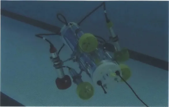
1-1 T hesis Tree . . . . 3-1 3-2 3-3 3-4 3-5 3-6 3-7 3-8 3-9 3-10 3-11 3-12 4-1 4-2 4-3 4-4 4-5 4-6 4-7 23AMOUR VI robot, thrusters, and human input device . . . . 47
Inertial Measurement Unit . . . . 48
AMOUR VI System Overview . . . . 49
AMOUR VI configured with 5 thrusters in the water. . . . . 51
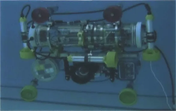
AMOUR VI configured with 8 thrusters. . . . . 52
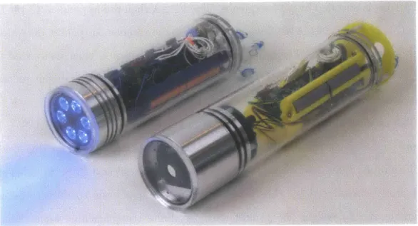
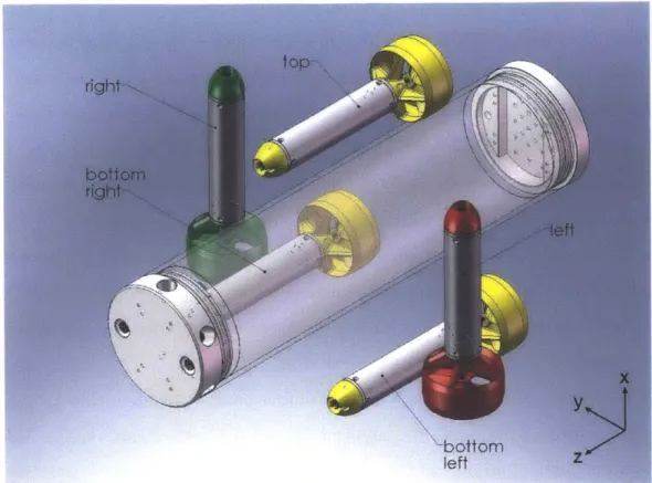
Two AquaOptical II modems . . . . 52
AquaOptical I modems. . . . . 53
Overview of the AquaOptical II hardware and software . . . . 53
Two AquaOptical II modems with the acrylic housing removed . . . . 55
AquaOptical Micro next to AquaNode. . . . . 58
Digital Pulse Interval Modulation. . . . . 59
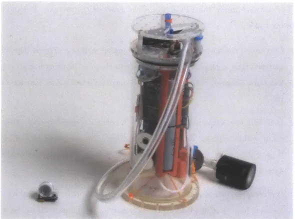
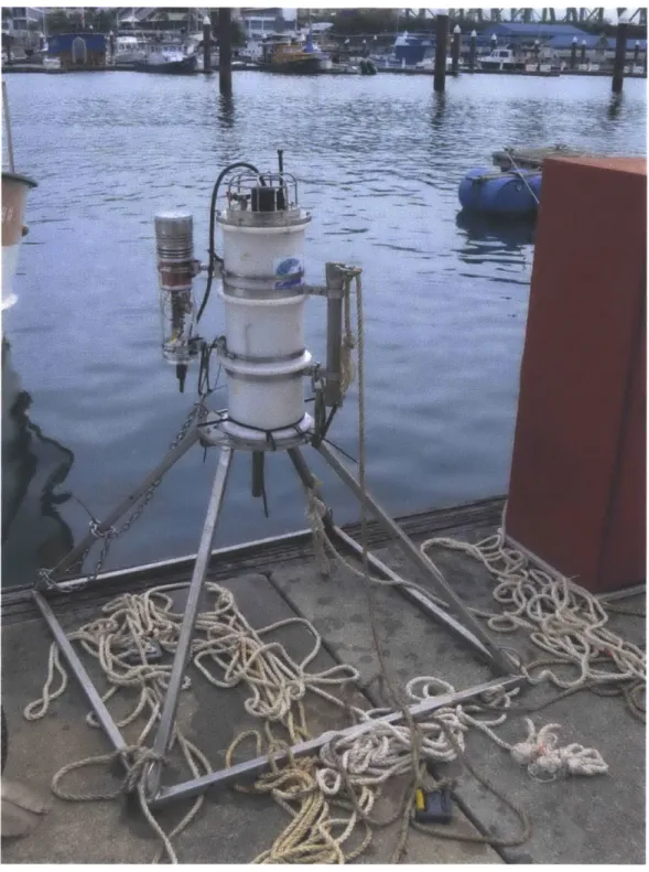
PANDA node with AquaOptical II attached. . . . . 62
Modular Thruster Control Algorithm. . . . . AMOUR VI with 5 thrusters . . . . AMOUR VI user interface . . . . Experimental results for pitch and roll step response . Control algorithm performance for 5 and 6 thrusters . Thruster estimation algorithm simulation results . . . . Convergence of the thruster rotation matrix estimation. 4-8 The thruster configurations used in the hardware experiments . . . 4-9 Experimental data and results of the thruster estimation algorithm . . . . 66 . . . . 68 . . . . 78 . . . . 79 . . . . 81 . . . . 85 . . . . 88
89
904-10 Experimental results showing performance of robot with thruster
po-sitions estimated by the algorithm . . . .
91
5-1
AquaOptical II transmitter test setup . . . .
94
5-2
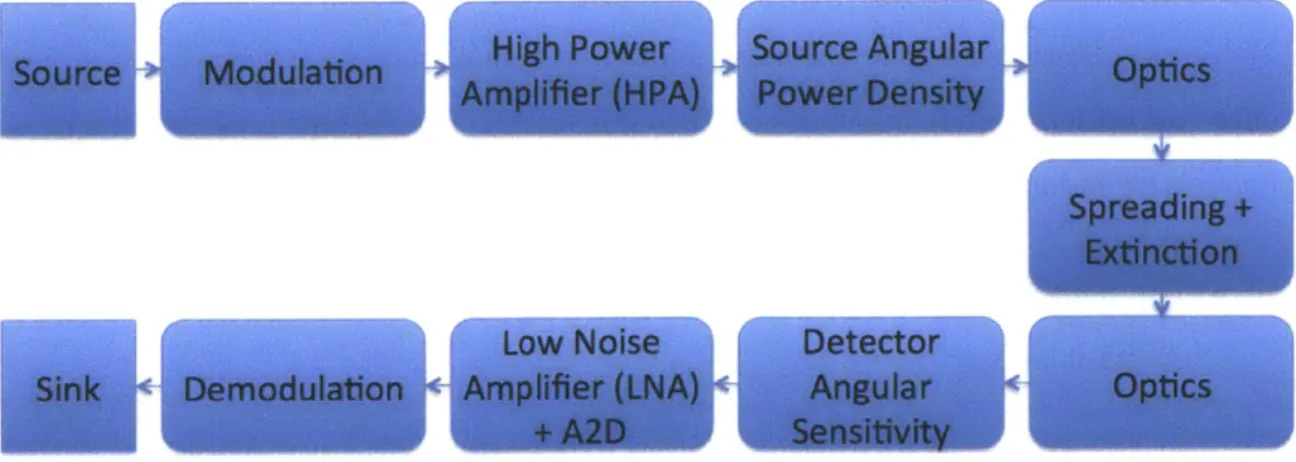
Block diagram of end-to-end signal strength model. . . . .
96
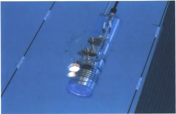
5-3 AquaOptical II transimpedance amplifier with photodiode . . . 102
5-4 AquaOptical II system overview for data and video transfer . . . 103
5-5 AquaOptical II LED radiant intensity . . . 105
5-6 AquaOptical II modeled transmitter radiant intensity . . . 105
5-7 AquaOptical II modeled relative receiver sensitivity . . . 106
5-8 AquaOptical II model validation experimental setup . . . 108
5-9 AquaOptical II test setup . . . 109
5-10 AquaOptical II header code . . . 110
5-11 AquaOptical II modeled signal strength and experimental data
1
. . . 1125-12 AquaOptical
II
modeled signal strength and experimental data 2 . . . 1135-13 AquaOptical II modeled signal strength and experimental data heatmap114
5-14 Maximum model errors when compared to experimental data. . . . . 115
6-1 Data muling theoretical performance . . . 121
6-2 Sample simulation results of acoustic gradient descent and particle filter128
6-3 Acoustic gradient descent and particle filter simulation results . . . . 1296-4 Data muling experimental setup at Republic of Singapore Yacht Club 130
6-5
Data muling experimental setup at Pandan Reservoir in Singapore . . 131
6-6
Results of two optical gradient descent experiment runs . . . 133
6-7 Results of data muling experiments . . . 134
6-8 Results of acoustic particle filter experiments 100 m . . . 135
6-9 GPS ground truth for acoustic particle filter experiments 100 m.
.
. .
136
6-10 Results of acoustic particle filter experiments 200 m+ . . . ..
137
6-11 Results of combined acoustic and optical particle filter experiments
.140
7-2 AquaOptical remote control system overview . . . . 145
7-3 Optical Modem System Overview. . . . . 146
7-4 AMOUR VI during optical remote control . . . . 149
7-5 Optical signal reception in the center of the pool . . . . 151
7-6 Average remote control latency . . . . 153
7-7 Performance of the optical system while using HID . . . . 154
8-1 AquaOptical II modem mounted on an underwater test rig. . . . . 158
8-2 AquaOptical II video system overview . . . . 159
8-3 Two-layer error coding scheme . . . . 161
8-4 Structure of packets sent by the AquaOptical II modem. . . . . 162
8-5 Experimental testbed for underwater video transmission . . . . 164
8-6 Sample acquired camera frame during benchtop trial . . . . 165
8-7 Frame reception success rates for different video qualities . . . . 166
8-8 Frame reception success rates at different modem-to-modem distances 167 8-9 Frame latency at different ranges, as a function of JPEG quality . . . 168
8-10 Image properties for the video streams as a function of JPEG quality 169 8-11 Fragment reception success rates for all pool trials, vs. distance . . . 170
8-12 LT overhead histograms for transmission over 25 m and 35 m . . . . . 171
8-13 LT overhead as a function of modem ranges . . . . 172
8-14 Histogram of time intervals between consecutive fragments received . 173 8-15 End-to-end latencies for capturing real-time video . . . . 174
8-16 Fragment reception success rates for all experimental site trials . . . . 175
8-17 Frame reception success rates for all pool trials, vs. distance. . . . . . 176
Chapter 1
Introduction
1.1
Vision
More than 70% of our planet is covered by water. It is widely believed that the un-derwater world holds ideas and resources that will fuel much of the next generation of science and business. This is evidenced by the hundreds of millions of dollars in fund-ing dedicated towards the development of underwater observatories [30]. The concept of an underwater observatory, suggested no later than 1870 by Jules Verne [122], has recently become a reality with cabled networks as NEPUTE
[15],
VENUS [16], and MARS [66]. All of these systems provide researchers with the ability to install and connect with long term instrumentation at fixed locations in the water. However, currently these systems are limited in scope to deployments at or near designated instrumentation sites.We envision underwater observatories in which robots and in-situ static and mo-bile sensors collect information about the underwater environment and deliver this information to remote users with little or no spatial constraints, much like a mobile web-cam delivers remote data to users on the ground. Such observatories would act mostly without human intervention, allowing for easy and safe collection of data. They could be deployed to monitor corral reefs like the Great Barrier Reef, deep ocean environments, such as the Marina Trench, or surveil marine areas important to national security, such as coastal lines.
However, today's underwater operations are fraught with difficulty due to the ab-sence of an easy way to collect and monitor data at high data rates on the order of Megabits per second and with comprehensive area-coverage. Although underwa-ter sensors exist, they lack much of the functionality needed in such an underwaunderwa-ter observatory:
" The position of sensors is fixed resulting in a limited spatial scope for data collection with individual sensors;
* Collecting the data is subject to very long delays which is prohibitive to live data streams such as video feeds;
" Individual sensors are unable to perform operations that require cooperation, such as tracking relative movement and locating events.
What is required is a low-cost, versatile, high-quality, and easily deployable plat-form for underwater observatories that will
" provide agile mobile nodes that can be controlled in 6 degrees of freedom (DOF), much like a webcam that can be repositioned remotely;
" provide and interface with sensors that collect high quality data, such as real color images and video;
e communicate data from the observatory to the user at a fast data rate and with minimal latency;
" communicate commands from the user to the observatory;
e automate data collection and scale-up in time and space, and
* be easy to use.
It is our goal is to develop the technologies that enable users to set up and interact with underwater observatories. We believe that an effective method for large-scale data transfers (which are required when uploading the data collected by an underwater
sensor network) is optical data muling. In optical data muling, a robot equipped with an optical modem visits each node of the sensor network and uploads its data while hovering within optical communication range. Previous work has described an underwater sensor network system capable of uni-directional optical data muling using GPS to find the sensor node [116]. However, the data transfer performance of the entire system was limited by the optical modem's maximum data rate of 320 Kbps.
In this thesis, we propose developing a new generation of an underwater data collection system, whose performance is a significant improvement over the state of the art, and several applications of underwater communication. This system is also based on a data muling approach and consists of two major components. The first is an optical communications platform whose performance in both range and data rates exceeds that of state-of-the-art systems. The second is a highly maneuverable, versatile, and easily deployable underwater robot capable of mobile data collection and autonomous travel to a sensor site for optical data download.
1.2
Challenges
There are many challenges which must be overcome in order to achieve underwater data muling. The most important challenges include communication, estimation, and controls.
When trying to achieve underwater data muling, the first problem is a communi-cation problem. In order to successfully data mule, communicommuni-cation links with high data transfer rates of 1 Mbps and above must be established. Such data rates are necessary if we want to transfer high fidelity data, such as pictures, audio and video recordings. Attaining data rates of 1 Mbps and above is difficult even at short ranges below 50 m which are required in order to transfer data from a sensor node to the robot performing data muling. Conventional high-speed wireless communication re-lies on radio frequencies and does not work underwater at distances greater than a few meters. This is due to the strong absorption of electromagnetic radiation by
wa-ter across the majority of the frequency spectrum. Currently, the de facto standard for wireless underwater communication is the use of the acoustic channel. However, acoustic communication allows for only data transfer rates on the order of a few Kilobits per second that do not permit the download of large data files [70].
The second problem is an estimation problem. In order to establish a high-speed communication link, we need to come within range of the sensor node from which we intend to data mule. This requires localization of the underwater sensor node relative to the data muling robot. When distances between the robot and the nodes are large, and their locations are unknown, positioning the data muling robot within optical communication range is challenging. However, this is usually the case in large open environments, such as the ocean, where the deployment of large-scale locations networks still remains a major challenge. Rather than focusing on the development and use of such a network, we instead try to solve the problem with equipment provided solely via the sensor node and robot. Finally, once we have localized the sensor node, we need to continuously update our position estimates in order to maintain a position that is within communication range.
The third problem is a controls problem. The data muling robot has to approach the sensor node and subsequently maintain position within communication range. This is especially challenging as optical communication requires a direct line of sight between the transmitter and receiver in most cases. In addition, the robot is required to potentially transport sensors to and from the field of deployment. This wide range of tasks can be achieved with a modular robot whose thrusters can be easily repositioned, added, or removed from the system to ensure that the system can deliver and position the payload with the precision required by the task. Such a modular robot requires a robot configuration and control system that is very adaptive.
In summary, the design of an autonomous and efficient data muling system poses many problems, with this thesis addressing the following:
* Efficient control of a hovering underwater robot with n degrees of freedom (n
thrusters) on a curve in the Special Euclidean Group SE3. The robot is
This makes it difficult to compute a valid vehicle dynamics model. Thus, em-phasis is placed on controls without the existence of a vehicle dynamics model.
" Design of a device and algorithms for high bandwidth, point-to-point optical communication. This device forms the communication link for our system.
" Integration of robot control and optical communication to allow for autonomous and efficient data muling.
" Localization of the robot based on the optical link signal strength if an external localization is not available or too coarse in space or time.
1.3
Our Approach
In order to overcome the challenges presented above, we needed to focus on the development of hardware as well as algorithms.
To address the problem of high-data-rate underwater communication, we devel-oped an underwater wireless communication device called AquaOptical, which uses visible light to transmit data at rates of up to 8 Mbps. We have investigated ways to maintain these data rates while maximizing our communication range. In particular, we have focused on minimizing the requirement for pointing of the transmitter and receiver at each other. This simplifies establishing and maintaining communication links. Further, we focused on a device that is practical, i.e., that can be constructed and deployed at a reasonable cost. This requires a careful choice of components, atten-tion to form factors and power consumpatten-tion, and the development of low-complexity communication algorithms that can be implemented within the hardware constraints of the system. In order to allow easy experimentation with different communication codes and protocols, we developed the optical modem to work as a "software defined radio" [40, 82]. This also allows the system to adapt to the environment by easily changing its coding.
To address the estimation problem of locating the sensor, we focused on two as-pects. First, we developed a method for reliable measurement of the optical signal
strength arriving at the receiver and a model to predict this signal strength. We showed that if we are within optical communication range, then the signal strength measurements can be used to estimate the location of the sensor node. We use two methods to integrate these measurements into a location estimate: (1) gradient de-scent and (2) a particle filter. The latter can be integrated with the signal strength model to significantly improve estimation performance. The second aspect of our solution focuses on combining the estimation (based on optical signal strength) with acoustic ranging. The integration of an acoustic signal is necessary not only because it extends our location estimation capability beyond the short range of optical com-munication, it can even improve the overall estimation performance. Also, it allows for high-level message passing, such as turning the optical communication device on and off and thus saving power on the sensor.
We tackle the controls problem through the development of an underwater robot system, whose dynamic properties can be adjusted in real time, and the algorithms re-quired to control this system. Specifically, we developed modular underwater robots whose thruster configuration can be adjusted on the fly, by adding, removing, or repositioning thrusters. We focus on the key challenge to develop a robot control system capable of adapting to changing robot dynamics in situ, without human re-programming. In order to do so, we develop an algorithm for controlling a robot with arbitrary but known thruster configurations. The algorithm allows for full control of the robot's position and attitude in the special euclidean group SE', provided that this is possible with the current thruster configuration. SE3 is the group of all three
translational plus all three rotational degrees of freedom. We then present an algo-rithm for in-situ estimation of previously unknown thruster configurations of modular underwater robots.
Finally, we combine these three aspects of our solution to create an autonomous underwater data muling system that can retrieve data from sensor nodes of previously unknown location. The final algorithm has three phases. In the first phase, acoustic communication is used to bring the data muling robot within some close range of the desired sensor where it can detect the optical signal. In the second phase, the robot
AMOUR
V1
Aqua~ptical
UNET2-PANDA
Co
Position and Attitude Control with unknown
Vehicle Dynamics
Expenent s
Figure 1-1: Thesis tree.
does a local search using the optical signal strength to precisely locate the sensor and
position itself within communication range. In the third phase the robot uses optical
communication to collect the data from the sensor. In practice, phases two and three
overlap once the signal strength becomes strong enough to transmit data.
1.4
Thesis Contributions
In this document, we aim to examine the following thesis:
Underwater Data Retrieval can be effectively achieved using Data Muling with
Combined Underwater Optical and Acoustic Communication.
To do so, we focus on the development of high-data-rate underwater optical
com-munication systems and their integration with existing acoustic comcom-munication
sys-tems. We show that together with appropriate communication, estimation, and
con-trol algorithms, they can be used to achieve autonomous underwater data retrieval
at unprecedented data rates.
The main contributions of this thesis are illustrated in Figure 1-1. They can be
grouped into different parts:
High Bandwidth Point to Point 0pic; Communication
Data Muling
mmunication AcutcadOtcl RaTmeRmt RelT eVde
Hardware GrdetDset RbtCnrl Tasiin
-
~
~ ~
c to wit~
~
uncto Re ot Coto~
~
~
Vie Trasmis. o... ..Firmwre aPartcleiar ExermnsExe et
* Hardware
Algorithms
Experiments Optical Communication Applications
Exeimna I
" The first group comprises hardware contributions. In particular, we present a novel modular underwater robot for which the user can arbitrarily reconfigure the robot's thrusters to adapt to the task at hand (such as transporting an acoustic and optical modem or a sensor node). We further present the optical communication system we developed, called AquaOptical, which allows for high-data-rate (>1 Mbps) wireless underwater communication.
" The second group, Position and Attitude Control with unknown
Ve-hicle Dynamics presents two algorithms. The first allows for control of a robot in SE3 with previously known thruster configurations. The second algo-rithm estimates these thruster configurations. Together these algoalgo-rithms allow the user to assemble the robot, autonomously estimate its control parameters (thruster configuration), and then control it in all three translational and all three rotational degrees of freedom.
" The next group, High Bandwidth Point-to-Point Optical
Communica-tion, presents the algorithms used by AquaOptical. We present the low-level codes used, as well as algorithms to detect and decode data packets. Further, we present a method for reliable estimation of the received signal strength and a model for predicting this signal strength.
" The fourth group is Data Muling. It presents algorithms that combine the previous contributions to achieve data muling. In particular, we present an algorithm that locates the sensor node using gradient descent on the acoustic and optical signal. The second algorithm presented in this group improved localization of the sensor node through the use of a particle filter. Finally, we present algorithms for robust transfer of data from the sensor node to the robot, while minimizing power consumption on the sensor node.
" In the final group, Optical Communication Applications, we present two additional uses of our underwater system. The first is real-time remote robot control, in which we use AquaOptical to remotely control our underwater robot.
The second is real-time video transmission that allows us to close the loop between the user and the robot.
All algorithms and systems presented in the thesis are verified experimentally. In summary, this thesis contributes the following:
o The concept of, and the algorithms to implement, data muling using combined acoustic and optical communication.
o Design of a device and algorithms for high-bandwidth point-to-point optical communication.
o An end-to-end model of signal strength in underwater optical communication, along with an experimental evaluation of the model using the AquaOptical II modems.
o Design of a modular and reconfigurable thruster system for an underwater robot which allows the robot to adapt to different use cases.
o An algorithm for efficient control of a reconfigurable hovering underwater robot with n degrees of freedom (n thrusters) on a curve in the Special Euclidean
Group SE3
.
o An algorithm for estimating thruster configurations of a reconfigurable hovering underwater robot with n degrees of freedom (n thrusters).
1.5
Thesis Outline
The remainder of this document is organized as follows. In Chapter 2, we present existing research related to this thesis. In particular, we present related works in the fields of underwater optical communications, localization in the context of data mul-ing, and vehicles controls. In Chapter 3 we present the underwater robot AMOUR VI and AquaOptical II communication hardware developed in the context of this thesis as well as the underwater sensor network PANDA, which has been integrated into our
data muling system. Chapter 4 presents the control algorithms developed to achieve
six degree of freedom control for arbitrary configurations of AMOUR VI. Chapter
5 presents a model for estimating optical signal strength for underwater
transmis-sion and the model is experimentally validated using AquaOptical II. In Chapter
6 we present the algorithms developed for estimating a single nodes location based
on acoustic ranging and optical signal strength measurements. We further present
experimental data muling results. Chapters 7 and 8 present additional use cases of
AquaOptical II for data transfer and remote robot operation. Specifically, Chapter 7
presents a system for wireless real-time remote control of AMOUR VI and Chapter
8 presents algorithms for wireless real-time transmission of video using, both using
AquaOptical II. Finally, Chapter 9 discusses the lessons learned from developing our
system and presents an outlook into possible future research directions related to this
thesis.
Chapter 2
Related Work
This Chapter highlights prior works related to the algorithms and systems presented in this thesis. First we address prior art in underwater wireless communication in Sec-tion 2.1. SecSec-tion 2.2 focuses on works related to wireless underwater video streaming. existing research related to data muling and in particular the location estimation problem is reviewed in Section 2.3. Finally, in Section 2.4 we give an overview of
AUV control literature.
2.1
Underwater Optical Communication
Underwater optical communication has received a great deal of interest in the recent years despite still being a very young field of research. Before visible light was used for underwater communications it was in use for communications through air as reviewed
by Smyth et al. [104]. The use of light emitting diodes (LEDs) for wireless over the
air communication of audio signals was reported in by Pang et al.
[88].
Bales et al. proposed the use of optical communication underwater and com-puted that data rates of 10 Mbps should be possible over distances of 20 m with off the shelf components [14]. An early stage underwater communication system re-ported by Tsuchida et al. uses optical communication to transmit measurement data
from non-tethered crayfish in a laboratory tank [108]. This was quickly followed
al. and Vasilescu et al. proposed optical communication for swarms of underwater vehicles [107, 96, 119]. Dunabin et al. proposed the use of optical communication for data muling where an underwater vehicle approaches a sensor and downloads data using a short range but high speed optical link
[48].
In this thesis we expand on this idea and provide a system that is capable of data muling in open water environments at scales of kilometers. Optical remote control of underwater vehicles is demonstrated by Farr et al. at large ocean depths where no ambient light is present [55]. Our sys-tem allows remote control of underwater vehicles in environments with ambient light present.Many of the systems implemented today have not been analyzed methodically to determine factors that influence their transmission ranges. Often ranges were measured during field experiments and the best range was reported. Some in-depth characterizations of transmission ranges have been performed in laboratories with large modem setups, but they are not field-ready. Chancey et al. measured the performance of their 10 Mbps system with the transmitter and receiver aimed at each other in a water tank at a distance of 4.6 m [22]. Hanson et al. demonstrated a laser based system capable of data rates of 1 Gbps over a 2 m path in a tank with 36 dB extinction (absorbents were added to the water) [65]. Their system's performance is impressive, but it is based on a bulky, fragile, and power inefficient laser setup that is not practical in the context of a small underwater robot.
Jaruwatanadilok et al. proposed a channel model for optical underwater communi-cation that uses vector radiative transfer theory [68]. Smart et al. explored the theory of optical transmission in water and suggested possible optical modem designs [103].
Giles et al. gave a model for computing achievable transmission range for a given setup when pointing both devices at each other. They considered both light source power and detector sensitivity as well as extinction through the water [61]. Gabriel et al. proposed a model for simulating channel impulse response [58]. They used Monte Carlo simulations of their model to show that channel time dispersion is negligible in most practical cases, even for data rates of 1 Gbps over a distance of 50 m with water turbidity equivalent to 7.5 e-folding lengths over 50 m. Kedar et al. proposed
a model for non-line-of-sight (NLOS) underwater optical communication [69]. In this thesis we present an optical signal strength model based on physical analysis of all components in the communication path.
The reminder of Section 2.1 gives an overview of current and past optical modem developments organized by different research groups.
2.1.1
Woods Hole Oceanographic Institution
Farr et al. estimate the transmit power required to maintain a bit error rate (BER) of
10-6 for various data rates and distances [53] [54]. Their model combines absorption
and scattering losses in water into a single constant attenuation loss ec" for a dis-tance R. This is Beer's law. They assume an e-folding length of 36 m. For a system using LEDs and a photomultiplier tube (PMT), they compute a required transmit power of 300 mW for a data rate of 10 Mbps at 100 m with a 13.4 cm large receiver aperture and 90 degree transmitter beam. If the receiver aperture is reduced to 5 cm and the transmitter beam to 10 degrees, the required power for the same data rate and distance drops to 6.5 mW. They argue that multi-path and signal spreading has no significant effect on data rates below 10 Mbps. Further, they propose that back-ground noise caused by bioluminescence and Cherenkov radiation is low enough that it does not interfere with the signal. They create a test setup with 6 potted LEDs transmitting in a 27 sr hemisphere and a bi-alkali PMT receiver with quantum effi-ciency of 20 % and a gain of 107, driven at 400 to 500 V. They test their system at the Woods Hole docks over a distance of 10 m by sending 1, 5, and 10 MHz square pulse trains and record SNR values of 30 to 35 db. According to the numbers reported by Farr et al. their 90 degree transmitter system is theoretically capable of transmitting 33 Million bits/Joule radiant power over a distance of 100 m. However, the number reported during future deployments of their system is lower at 40,000 bits/Joule.
Pontbriand et al. use a 17 inch diameter glass sphere to improve the field of view[92]. The sphere houses a PMT, and they use an external power source and feed the output signal to an external digitizer. Their system communicates at rates up to 5 Mbps and distances up to 200 m at an e-folding length of 40 m. In turbid water
with an e-folding length of 0.8 m, they achieve 1 Mbps. Their tests are performed in
Bermuda and at the Woods Hole dock.
In [52] and [55], Farr et al. describe the Optical Telemetry System (OTS) with
which they download 20 MB of data over a 5 Mbps link at a range of 80 m. They
report communication at a data rate of 10 Mpbs at a distance of 108 M, 5 Mbps at
distances of up to 128 m, and 1 Mbps at distances of up to 138 m. Additionally, they
provide optical signal power measurements at various distances. For a source power
of 15-20 W they report incident power of approximately 2. 10-7 W at 50 m, 10-8 W
at 100 m, and 2. 109 W at 150 m.
Camilli et al. [21] discuss the application of optical communication to ocean
ob-servatories and claim that it allows for 10 Mbps with ten or more e-folding scales
resulting in communication distances of 100-200 m. They categorize optical
commu-nication as permitting data rates on the order of 1 Mbps at distances close to 100 m
at an energy expenditure of 40,000 bits/Joule.
In comparison, our AquaOptical II system utilizes an Avalanche Photodiode
be-cause of its increased dynamic range [71] and quantum efficiency [1]. It operates
over distances of 50 m at a data rate of 4 Mbps with an energy expenditure of
400,000 bits/Joule radiant power. This results in 120,000 bits/Joule when including
the total combined power consumption at the transmitter and receiver. Further, the
system can cope with ambient light allowing operation near the water surface.
2.1.2
North Carolina
In [22], Chancey uses an amplifier to drive a 1 W LED with a 10BaseT Ethernet
signal and a photodiode detector on the receiving side that converts the incoming
light pulses back to the 10BaseT range. His design is based on an existing free space
optical communication implementation called RONJA. He tests his system in a water
tank over a distance of 4.6 m and extrapolates that the potential link distance is
16 m.
In [32], Cox uses a 405 nm laser for transmission and the miniature Hamamatsu
R7400U PMT in conjunction with an AD8015 variable gain amplifier (VGA) on the
receiving side. His system is tested using a water tank with reliable communication at 500 Kbps.
Using the same laser diode and a PNZ334 photodiode and a PC for post processing, Cox et al. show that the use of forward error correcting (FEC) codes achieves a BER of 10--4 at SNR levels 8 dB lower than without FEC
[34].
They use on-off keying (OOK) in a return-to-zero (RZ) coding to transmit data at a rate of 500 kbps through water in a 3.66 m long tank. They vary the SNR by changing the attenuation coefficient of the water through the addition of Maalox. Their uncoded stream achieves approximately a BER of 0.5 at 6.5 dB SNR, 10-1 at 8.5 dB, 10-2 at 12 dB, 10- at 16 dB, and 10-4 at 19 dB. When using a (255,129) Reed-Solomon (RS) code, they achieve a BER of10-4 at SNR 11 dB.
Simpson et al. show through simulation that, for a BER of 10-6, the (255,223) RS code provides an SNR improvement of 4 dB and the (255,129) RS code provides
an SNR improvement of 6 dB [99]. They transmit data through a water tank using a 3 W LED (CREE XR7090) at 470 nm and 525 nm. They use two setups: in one they transmit over a length of 3 m through turbid water (4+ e-folding lengths) and in the other over a length of 7.7 m through less turbid water (1-2 attenuation lengths). A PMT is used to receive the first (weak) signal and a photodiode to receive the second (stronger) signal. Their equipment is battery powered, but the signal is digitized at 100 MSPS (20 times oversampled) using external equipment. They use a matched filter to maximize SNR and early-late gate symbol synchronization. Their system achieves 5 Mbps throughput.
In [101], Simpson et al. propose a two-transmitter two-receiver spatial diversity system. They use a 200 mW, 405 nm laser together with a beam splitter to generate two parallel optical beams separated by 10.2 cm. Two 25.4 mm lenses focus the light onto two Thorlabs PDA36A amplified photo detectors. They investigate the use of equal gain recombination and maximum recombination for the two received signals. They transmit through a water tank into which they inject bubbles to generate in-terruptions of the optical beam. They show that their setup, using a data rate of 500 Kbps, reduces fading-induced errors by a factor of 10 when compared to a single
200 mW transmitter, single detector system.
Another novel approach is proposed by Cox et al. in [33]. They designed a MEMS
Fabry-Perot modulated reflector that is used to modulate an existing optical beam.
The reflector can be attached to a node or vehicle, and a querying node or vehicle
shines an optical beam on it and receives the reflected and modulated signal. They
use a 20 mW, 532 nm laser and a Thorlabs PDA36A amplified photodetector at the
querying node. They demonstrate data rates of 500 Kbps to 1 Mbps using quadrature
phase shift keying (QPSK) through a 7.7 m long tank corresponding to 2.5 e-folding
lengths. Their system uses little power for the reflector but requires the beam to
travel twice the transmission distance.
In [35], Cox et al. implement a complete duplex communication system based on
410 nm, 30 mW laser diodes and a Thorlabs PDA36A amplified photodiode receiver
with a 51 mm collection lens. They use two Ettus Research USRP signal acquisition
boards together with GNU radio software to generate the transmitted signal and to
decode the incoming signal. Tests are conducted in a 3.66 m long tank, and different
attenuation coefficients are achieved with the addition of Maalox to the water. When
using 1 Mbps binary phase shift keying (BPSK) they measure the BER to be 0.2 at a
SNR of 4 dB,
10-2at 7 dB,
10-3at 9 dB, and 10- at 10.5 dB. A duplex networking
test is performed using 1 Mbps Gaussian minimum shift keying (GMSK) modulation.
They achieve round trip latencies of below 10 ms at up to 5.3 e-folding lengths.
With AquaOptical II we implemented a two-layered coding scheme that can be
made invisible to the user. We use a reconfigurable Reed-Solomon inner code with a
system Luby Transform (LT-code) outer coder. We chose to utilize LED light sources
instead of lasers in order to maintain eye-safety for human operators and to reduce
pointing requirements. Because of its large aperture of 7 cm and non-focused beam
AquaOptical II implicitly implements a spatial diversity system that achieves low
bit-errors due to air bubbles and other scattering agents in the water.
2.1.3
Naval Air Warfare Center (NAVAIR), Patuxent River,
MD
Cochenour et al. use laser modulation with a 70 MHz radio frequency (RF) carrier and BPSK to achieve error free communication at a data rate of 1 Mbps through highly turbid water
[29].
They use a frequency-doubled diode-pumped solid-state laser with a wavelength of 532 nm and an output power of 3 W. This continuous wave (CW) optical signal is modulated using an electro-optic modulator. The optical power transmitted into the water is approximately 500 mW after losses through the optical modular and other optical elements. The detector is a PMT with a 51 mm aperture, corresponding to 18 degrees field of view. The received RF signal is bandpass filtered at 70 MHz and amplified by a 30 dB low noise amplifier (LNA) and a 50 dB variable gain amplifier (VGA). An IQ demodulator extracts the I andQ
channels, which are lowpass filtered and digitized using a National Instruments DAQ card. The system is tested in a 3.6 m water tank with the turbidity of the water controlled through the addition of Maalox. A pseudorandom 1024-bit sequence is used to measure bit errors. The transmitted signal is recovered error free even at a turbidity that is equivalent to 90 e-folding lengths at 3.6 m. The phase error for the BPSK never exceeds 3 degrees.However, the authors point out that this surprisingly good result might be due to the small geometry of the tank.
In
[28]
this work is extended to quadrature phase shift keying (QPSK), 8 phase shift keying (8-PSK), 16 quadrature amplitude modulation (16-QAM), and 32-QAM. Tests are conducted again in a 3.6 m water tank with water turbidity adjusted to 8.4 e-folding lengths for the length of the tank. Data is sent at 106 symbols per second, resulting in data rates from 1 Mbps for BPSK to 5 Mbps for 32-QAM. Two transmission powers are used in the tests. With a signal power of 750 mW entering the water, all modulation schemes yield BER of 10-' or better. When a signal powerof 75 mW is used, BPSK yields BER 0, QPSK yields BER 10-3, 8-PSK yields BER
greater than 0.1, and 16-QAM and 32-QAM fail to establish a link.
beam. The goal is to allow communication with less pointing accuracy or even
non-line-of-sight (NLOS) links. Measurements are taken by sending 10 ns laser pulses at
100 MHz and using a PMT with 1 GHz bandwidth. The pulse shapes are examined
for a collimated laser beam and for a laser beam that has passed a diffuser creating
a beam with a 20 degree field of view. The authors conclude that the NLOS link
requires at least 30 dB more transmission power to achieve a similar signal level at
the receiver.
Through the use of LEDs the light emitted from AquaOptical II is inherently
de-collimated. In comparison to the above work the LEDs have a lower bandwidth
which prohibits RF modulation. However, we utilize Barker-codes for packet detection
which separates the signal from the background noise and Manchester coding for bits
which is related to binary phase shift keying (BPSK). The use of LEDs allows for
smaller and cheaper devices, increase eye-safety, and reduces aiming requirements.
2.1.4
University of Genoa
Anguita et al. implement a transmitter that uses 12 LEDs arranged on a circle to
transmit omnidirectionally in the plane [4], [5], [8], and [7]. In two different
imple-mentations they use two different LEDs. The first is a Ledman LL1503PLBL1-301
with optical power 15 mW and a 30 degree field of view (50 % power angle). The
second is an Evergreen Electronic DLE-038-045 with optical power 20 mW and a
30 degree field of view. They propose an 18 LED omnidirectional transmitter design
in the shape of an octahedron. Their receiver consists of a Hamamatsu S5971 APD
with an area of 1 mm
2and a sensitivity of 0.2 A/W at 470 nm. The output signal is
fed through a 10 KHz to 20 MHz bandpass filter, an amplifier with automatic gain
control (AGC) based on LT1006, and a comparator to digitize the incoming signal
using thresholding. The optical physical layer (PHY) is implemented inside a field
programmable gate array (FPGA) on a Digilent Spartan 3 development board. They
test their system with a square wave at distances of up to 2 m and report the voltage
swing after the AGC. They show that their AGC allows for pulse detection from
dis-tances of a few cm to 10 m in air. Using 4- and 16-pulse-position-modulation (PPM)
they report a data rate of 100 Kbps over a distance of 1.8 m in a clean water tank. The analog front end of AquaOptical II digitizes the received signal at a resolution of 12 bits at 32 MSPS as opposed to the threshold filter described above. This allows us to implement a wide variety of available coding schemes for the physical layer, which is also housed inside an FPGA. An additional ARM processor is used by AquaOptical II to implement the MAC layer.
2.1.5
Commercial
Ambalux Corporation manufactures a commercial optical modem with a data rate of 10 Mbps [3]. They claim transmission distances of up to 40 m. Their modem inter-faces over 10BaseT Ethernet and allows TCP/IP and UDP communication. Power is provided externally, with the transmitter consuming 36 W and the receiver 7.2 W. The units are rated to a depth of 60 m. Ambalux Corporations claims that higher bandwidths up to 1 Gbps and larger operating depths up to 6000 m can be achieved. However, no such device is currently available to the public.
Baiden et al. used an Ambalux Corporation modem in [11] and [13]. Their tests were performed at Long Lake in Sudbury, Ontario and in the pool. They achieved 9.69 Mbps over a distance of 11 m. In the pool they establish an 8.2 Mbps link at distances up to 21 m. Further, they present a novel spherical transmitter and receiver capable of transmitting at data rates of 20 Mbps over a distance of 10-11 m. The same
spherical transmitter
/
receiver pair achieves a data rate of 115 Kbps at distances of 15 m in the field.The devices developed by Baiden et al. are being commercialized by Pengiun
Automated
[90].
In comparison, AquaOptical II consumes 24 W at the transmitter and 10 W at the receiver when operating at full throughput over distances of 50 m. We currently allow for UDP connections over a 10BaseT Ethernet connection. Because of its re-configurable nature, AquaOptical II can be easily adapted to use TCP/IP or other protocols.
2.1.6
Other
Hanson et al. demonstrated a laser based system capable of error free data rates of
1 GBit/s over a 2 m path in a tank with 36 dB extinction
[65].
Maalox absorbents were
added to the water. This corresponds to 8.3 e-folding lengths. Their system uses a
7 mW, 532 nm laser generated from a 1064 nm source that is optically pumped using
a ytterbium-doped fiber amplifier and frequency-doubled with a periodically poled
lithium niobate (PPLN) crystal. They use an avalanche photodiode as a receiver.
Chen et al. use a 532 nm yttrium aluminum garnet (YAG) laser to generate 10 ns
wide, 200 mJ pulses [24]. This corresponds to a 2 MW laser and as a result they
can only generate pulses at 50 Hz. They use 256-PPM with bin size of 10 ns. They
successfully transmit data through a 50 m long water tank.
Hagem et al. implement a low cost and short range unidirectional optical
mo-dem [63]. They use frequency shift keying (FSK) at a data rate of 2.4 Kbps with
modulation frequencies of 10 and 12 KHz. Their implementation consists of a 520 nm,
1.5 mW photodiode with a 70 degree field of view and an optical detector with a
sen-sitivity of 0.3 A/W. They achieve error free communication at distances up to 1.1 m
underwater without bubbles and up to 0.7 m with bubbles.
Lu et al. use a RL5-G13008 Super-Green LED, with a wavelength of 520 nm and
a maximum power of 120 mW, and a Silonex SLD-BG2A photodiode together with a
band-gap filter to reject infrared wavelengths [77]. The transmitter had a field of view
of 90 degrees, and the receiver a field of view of 120 degrees. They use a 32-bit Gold
sequence as a packet preamble for clock synchronization. They tested their system in
a pool at night to avoid ambient light. The system detected 80 % of the transmitted
packets at a communication distance of 10 m. Over 95 % of the packets were detected
at 6 m and below. The BER was approximately 1.8. 10-3 at 2 m, 3.5 . 10-2 at 6 m,

![Figure 5-12: Modeled signal strength and experimental data. The x-axis shows dis- dis-tance in [m]](https://thumb-eu.123doks.com/thumbv2/123doknet/14137500.469882/113.918.134.780.109.594/figure-modeled-signal-strength-experimental-data-shows-tance.webp)
