Publisher’s version / Version de l'éditeur:
Canadian Acoustics, 29, September 3, pp. 62-63, 2001-09-01
READ THESE TERMS AND CONDITIONS CAREFULLY BEFORE USING THIS WEBSITE.
https://nrc-publications.canada.ca/eng/copyright
Vous avez des questions? Nous pouvons vous aider. Pour communiquer directement avec un auteur, consultez la
première page de la revue dans laquelle son article a été publié afin de trouver ses coordonnées. Si vous n’arrivez pas à les repérer, communiquez avec nous à PublicationsArchive-ArchivesPublications@nrc-cnrc.gc.ca.
Questions? Contact the NRC Publications Archive team at
PublicationsArchive-ArchivesPublications@nrc-cnrc.gc.ca. If you wish to email the authors directly, please see the first page of the publication for their contact information.
NRC Publications Archive
Archives des publications du CNRC
This publication could be one of several versions: author’s original, accepted manuscript or the publisher’s version. / La version de cette publication peut être l’une des suivantes : la version prépublication de l’auteur, la version acceptée du manuscrit ou la version de l’éditeur.
Access and use of this website and the material on it are subject to the Terms and Conditions set forth at
Sound transmission through gypsum board walls : effect of shear
membranes and framing details
Nightingale, T. R. T.; Halliwell, R. E.; Quirt, J. D.
https://publications-cnrc.canada.ca/fra/droits
L’accès à ce site Web et l’utilisation de son contenu sont assujettis aux conditions présentées dans le site LISEZ CES CONDITIONS ATTENTIVEMENT AVANT D’UTILISER CE SITE WEB.
NRC Publications Record / Notice d'Archives des publications de CNRC:
https://nrc-publications.canada.ca/eng/view/object/?id=613dc796-27c7-4d1c-abf7-e6571f1944a8 https://publications-cnrc.canada.ca/fra/voir/objet/?id=613dc796-27c7-4d1c-abf7-e6571f1944a8
Sound transmission through gypsum board walls
-effect of shear membranes and framing details
Nightingale, T.R.T.; Halliwell, R.E.; Quirt, J.D.
A version of this paper is published in / Une version de ce document se trouve dans :
Canadian Acoustics, v. 29, no. 3, Sept. 2001, pp. 62-63
www.nrc.ca/irc/ircpubs
SOUND TRANSMISSION THROUGH GYPSUM BOARD WALLS: EFFECT OF SHEAR MEMBRANES AND FRAMING DETAILS
T.R.T. Nightingale, R.E. Halliwell, J.D. Quirt
Institute for Research in Construction, National Research Council, Ottawa, K1A 0R6
1. INTRODUCTION
This paper focuses on trends observed in the sound transmission results from a research project that studied both sound and fire resistance of wall assemblies intended for multi-family residential buildings. The National Research Council led the consortium project, with support from CMHC, Canadian Wood Council, Forintek Canada, Gypsum Manufacturers Canada, Ontario Min. of Housing, Owens Corning, Roxul, and Can. Home Builders’ Assoc. The series of 70 wall assemblies were all load-bearing constructions with gypsum board surfaces, but they varied in other details. Approximately half had framing of 16-20 gauge steel; the others were framed with wood studs plus a shear-bracing layer to increase the racking strength of the wall. To provide a basis for assessing the range of constructions in common use, the study included typical variations of component materials, as indicated in Figure 1.
Cavity Insulation
Resilient
Channels Resiliently Attached Gypsum Board one or two layers Direct Attached Layers
Gypsum Board and Shear Membrane, one layer each
Direct Attached Gypsum Board one or two layers
Figure 1: Horizontal cross-section through the wall assemblies. Assemblies are identified in captions using a short hand coding for components. For surfaces, ‘n’ layers of Gypsum board ‘xx’ mm thick is denoted: nGxx. Corresponding codes for Oriented Strand Board and Plywood are OSBxx and PLYxx respectively. For framing members ‘xx’ mm deep spaced ‘ss’ mm apart on centre, WSxx(ss), SSxx(ss), and RCxx(ss) denote Wood Studs, Steel Studs, and
Resilient metal Channels. Insulation in inter-stud cavities is denoted GFBxx, MFBxx, or CFLxx for Glass Fibre Batts, Rock Fibre Batts, or Cellulose Fibre ‘xx’ mm thick. For this key, all dimensions are rounded to the nearest mm; for example 12.7 mm gypsum board is listed as G13.
The discussion of factors controlling the sound transmission loss (TL) focuses first on factors controlling airborne
transmission, and subsequently on structure-related aspects.
2. FACTORS FOR AIRBORNE TRANSMISSION
Density of the surface layers is the single most important parameter. As shown in Figure 2, the typical improvement in transmission loss (and STC) is 4-5 dB when the number of layers of gypsum board (and hence the mass) is doubled on one side of the wall. Similar changes are observed with both wood and steel studs.
Increasing Layers of Gypsum Board
10 20 30 40 50 60 70 63 125 250 500 1k 2k 4k Frequency, Hz Transmission Loss, dB 1+1 STC 49 1+2 STC 54 2+2 STC 59
Figure 2: Adding layers of gypsum board to wall construction nG16_SS92(406)_GFB92_RC13(610)_mG16.
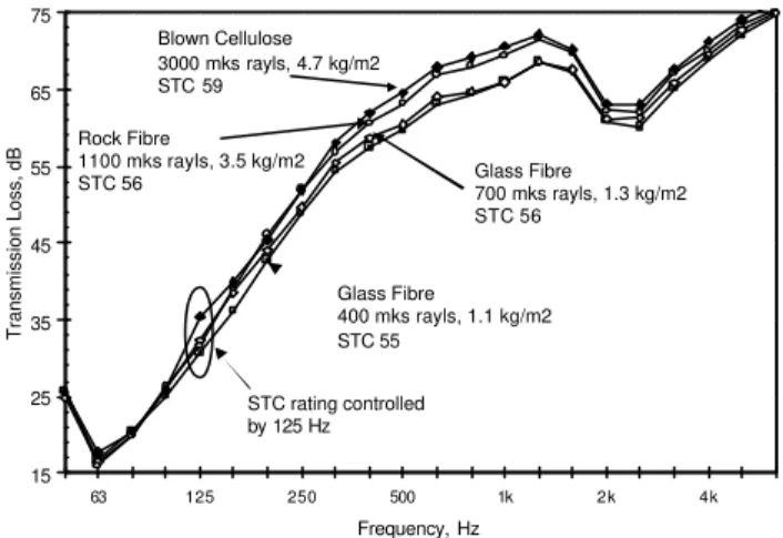
Adding cavity absorption improves the TL above 80 Hz, but the effect is smaller at the low frequencies that control STC for these walls. The type of insulation has a slight influence. Data in Figure 3 suggest that for frequencies above 400 Hz,
15 25 35 45 55 65 75 63 125 250 500 1k 2k 4k Frequency, Hz Transmission Loss, dB Blown Cellulose 3000 mks rayls, 4.7 kg/m2 STC 59 Rock Fibre 1100 mks rayls, 3.5 kg/m2 STC 56 Glass Fibre 400 mks rayls, 1.1 kg/m2 STC 55 Glass Fibre 700 mks rayls, 1.3 kg/m2 STC 56 STC rating controlled by 125 Hz
Figure 3: Varying the cavity insulation for wall constructions G16_OSB13_WS89(406)_xxx89_RC13(610)_2G16.
the airflow resistance of the fibrous insulation in the cavity controls the ranking of the walls’ transmission loss. The additional mass and any damping introduced by heavier fibrous materials in contact with the surfaces may also contribute. At low frequencies (where the STC tends to be determined and reproducibility is worse) the trend is much less clear. For the few cases with partly-filled cavities, the TL is lower than those shown in Figure 3, but the type of insulation seems less significant.
3. EFFECT OF STRUCTURAL ELEMENTS
Structural elements affect both structure-borne transmission and airborne transmission (via panel boundary conditions).
Resilient Channel Spacing
15 25 35 45 55 65 75 63 125 250 500 1k 2k 4k Frequency, Hz Transmission Loss, dB 2440 mm o.c. STC 63 406 mm o.c. STC 50 610 mm o.c. STC 55 1220 mm o.c. STC 61
Figure 4: Changing resilient channel spacing in constructions G16_OSB13_WS89(406)_GFB89_RC13(xxx)_2G16. Resilient metal channels are used to reduce structural transmission in these walls. As shown in Figure 4, the TL rises with greater inter-channel spacing (or equivalently, with fewer channels) approaching a limit as the structural transmission becomes negligible at very large spacing.
Comparison of Stud Type, Steel or Wood
15 25 35 45 55 65 75 63 125 250 500 1k 2k 4k Frequency, Hz Transmission Loss, dB 20 Gauge steel STC 60 16 Gauge steel STC 59 wood stud STC 56
Figure 5: Effect of changing stud type, in wall constructions 2G13_stud(406)_MFB90_RC13(xxx)_2G13. Because these steel studs are more compliant than wood studs of the same nominal depth, they give slightly greater
TL at the lower frequencies, as shown in Figure 5.
Regression analysis confirms this trend in STC versus stud type. The lower TL for 16 Gauge steel framing above 1 kHz is unexplained, and may be due to a construction anomaly.
Effect of Shear Elements
15 25 35 45 55 65 75 63 125 250 500 1k 2k 4k Frequency, Hz Transmission Loss, dB
no cross bracing or blocking, STC 51 cross bracing, STC 51
cross bracing and blocking, STC 52 OSB shear
membrane STC 57
Figure 6: Adding shear bracing to 20 gauge steel-framed wall G13_SS92(406)_MFB90_RC13(404)_2G13.
A major focus of this project was the effect of shear bracing on sound transmission. Figure 6 shows that blocking and/or cross-bracing straps have little effect on TL of these steel-framed walls. Adding an OSB layer gives the highest TL, mainly due to increased surface weight.
Shear Membrane Type and Thickness
15 25 35 45 55 65 75 63 125 250 500 1k 2k 4k Frequency, Hz Transmission Loss, dB 12.7 mm OSB (7.8 kg/m2), STC 55 11 mm OSB (6.7 kg/m2), STC 55 13 mm Plywood (5.6 kg/m2), STC 55 9.5 mm Plywood (4.5 kg/m2), STC 56 Maximum with 16 mm gypsumboard Minimum with 16 mm gypsumboard
Figure 7: Replacing G16 with shear membrane in wood-framed wall G16_xx_WS89(406)_GFB89_RC13(404)_2G16. Adding a shear membrane to a wood-framed wall also increases the TL. As shown in Figure 7, the four walls with wood-based shear membranes have quite similar TL. When the plywood or OSB layer is replaced with gypsum board (11 kg/m2), the TL changes slightly. The increase in surface weight should increase TL by ~2 dB at all frequencies, if behavior matched that in Figure 2. This expected increase is apparent below 500 Hz, but at higher frequencies specimens with the (lighter) shear membranes consistently exhibit higher TL, presumably due to typical stiffness and damping.