HAL Id: hal-02366814
https://hal.archives-ouvertes.fr/hal-02366814
Submitted on 16 Nov 2019
HAL is a multi-disciplinary open access
archive for the deposit and dissemination of
sci-entific research documents, whether they are
pub-lished or not. The documents may come from
teaching and research institutions in France or
abroad, or from public or private research centers.
L’archive ouverte pluridisciplinaire HAL, est
destinée au dépôt et à la diffusion de documents
scientifiques de niveau recherche, publiés ou non,
émanant des établissements d’enseignement et de
recherche français ou étrangers, des laboratoires
publics ou privés.
multiplexing
Aidana Beisenova, Aizhan Issatayeva, Iulian Iordachita, Wilfried Blanc, Carlo
Molardi, Daniele Tosi
To cite this version:
Aidana Beisenova, Aizhan Issatayeva, Iulian Iordachita, Wilfried Blanc, Carlo Molardi, et al..
Dis-tributed fiber optics 3D shape sensing by means of high scattering NP-doped fibers simultaneous
spatial multiplexing. Optics Express, Optical Society of America - OSA Publishing, 2019, 27 (16),
pp.22074. �10.1364/OE.27.022074�. �hal-02366814�
Distributed fiber optics 3D shape sensing by
means of high scattering NP-doped fibers
simultaneous spatial multiplexing
A
IDANAB
EISENOVA,
1A
IZHANI
SSATAYEVA,
1I
ULIANI
ORDACHITA,
2W
ILFRIEDB
LANC,
3C
ARLOM
OLARDI,
1,* ANDD
ANIELET
OSI1,4 1Nazarbayev University, Department of Electrical and Computer Engineering, 010000 Nur-Sultan (Astana),Kazakhstan
2Computer Integrated Surgical Systems and Technology Engineering Research Center (CISST ERC), Johns
Hopkins University, Baltimore, MD 21218, USA
3Université Côte d’Azur, INPHYNI–CNRS UMR 7010, Parc Valrose, 06108 Nice, France
4Laboratory of Biosensors and Bioinstruments, National Laboratory Astana, 010000 Nur-Sultan (Astana),
Kazakhstan
*carlo.molardi@nu.edu.kz
Abstract: A novel approach for fiber optics 3D shape sensing, applicable to mini-invasive
bio-medical devices, is presented. The approach exploits the optical backscatter reflectometry (OBR) and an innovative setup that permits the simultaneous spatial multiplexing of an optical fibers parallel. The result is achieved by means of a custom-made enhanced backscattering fiber whose core is doped with MgO-based nanoparticles (NP). This special NP-doped fiber presents a backscattering-level more than 40 dB higher with respect to a standard SMF-28. The fibers parallel is built to avoid overlap between NP-doped fibers belonging to different branches of the parallel, so that the OBR can distinguish the more intense backscattered signal coming from the NP-doped fiber. The system is tested by fixing, with epoxy glue, 4 NP-doped fibers along the length of an epidural needle. Each couple of opposite fibers senses the strain on a perpendicular direction. The needle is inserted in a custom-made phantom that simulates the spine anatomy. The 3D shape sensing is obtained by converting the measured strain in bending and shape deformation.
© 2019 Optical Society of America under the terms of theOSA Open Access Publishing Agreement 1. Introduction
The importance of shape sensing has significantly risen in the last decades, becoming a main research interest for the area of research, as well as for industrial necessities. In this context the shape sensors based on optical fibers (FOSSs) present advantages with respect to conventional shape sensors (CSSs), having a particular applications niche where precise measurements and minimal invasive sensors are required [1]. While CSSs, which can be categorized into electrical resistivity sensors, micro electrical mechanical systems (MEMS) sensors and optoelectronics sensors [2,3], are usually low cost but inaccurate and bulky, FOSSs are the best choice in bio-medical applications such as epidural administration, colonoscopy, cardiac procedures, robotic surgery and intra-arterial therapy [4–8]. Among the number of advantages shown by FOSSs, it is possible to underline that fiber sensors present a small form factor and a light weight (diameter of 125 µm or less), high sensitivity to temperature and strain, and chemical inertness [9,10]. Moreover, FOSSs are immune to external electromagnetic fields and are biocompatible [11]. The intrinsic small size of FOSSs is also associated to the possibility to implement multi-point or distributing sensing so that the interrogation unit can be placed in a remote place without the necessity of complicated and bulky wiring and connections [12,13].
#366078 https://doi.org/10.1364/OE.27.022074 Journal © 2019 Received 25 Apr 2019; revised 18 Jun 2019; accepted 18 Jun 2019; published 22 Jul 2019
The technology related to the problem of shape sensing, by the use of optical fibers, is mainly focused on the understanding of the fiber bending curvature and direction. The bending can be detected by measuring the induced cross-talking of the evanescent field in a multi-core structure, so measuring a change of optical intensity, or by detecting a strain induced by the fiber bending [14,15]. The last detecting strategy became predominant since the strain sensing can be easily implemented by using inscribed structure like Fiber Bragg Gratings (FBGs) [16,17]. An FBG consists of a periodic modulation of the core refractive index of a fiber which acts as a notch filter, permitting the reflection of a narrow band (typically, less than 1 nm) centered in a wavelength called Bragg wavelength. The reflected spectrum, as well as the Bragg wavelength, shifts with the variation of temperature and strain in the fiber [18]. The use of FBGs permits an easy demodulation of the stain. Nevertheless, the measurement obtained by an FBG is punctual, i.e. related to the location of the FBG. To achieve a multi-point, quasi-distributed measurements, an array of FBGs, each of them with a different Bragg wavelength, shall be inscribed in the fiber [19]. Furthermore, for a complete detection of the bending direction a structure with multiple fibers or a multiple core fiber, each of them with an inscribed array of FBGs, is required [12,20–22]. The geometrical arrangement of fibers/cores depends on the object geometry to shape, and on the degree of freedom of the target shape modification: 2D for an in-plane shape sensing, 3D for a shape sensing free of constrains [23]. In general, at least three fibers (or a fiber with three cores) arranged in a triangular shape are required for a full 3D shape measurement [12]. Adding a forth core and twisting the system can be useful for detecting torsion and for compensating the temperature [24]. Fibers with a larger number of cores, permitting the use of advanced shape reconstruction algorithms and permitting to achieve higher precision, are also investigated [25,26].
Multiple point sensing, achieved by multiplexing FBGs arrays over different fibers/cores, presents limitations related to distance between each FBGs, usually around 1 cm (center to center). This large distance can spoil the accuracy of the sensor, which is a strict requirement in critical medical applications [4,27]. Distributed sensing is the modern solution to improve the accuracy of optical sensors, and therefore the accuracy of shape sensors, by increasing the density of sensing points [28]. Distributed sensing is achieved by exploiting methods belonging to the family of optical frequency domain reflectometry (OFDR). The basic principle of OFDR concerns the spectral demodulation of the distributed reflections occurring in an optical fiber, given a large band source [29,30]. The optical backscattering reflectometer represents the practical implementation of OFDR principle [31]. The distributed reflection is given by the Rayleigh backscattering, naturally occurring in every optical fiber. Rayleigh scattering, mainly given by the reflective index fluctuation inside the glass material, presents a chaotic spectrum, dependent on the fiber position. Nevertheless, Rayleigh scattering nature is deterministic, and it can be used like a signature for the fiber. With this approach, the OBR allows a simple and low cost SMF-28 fiber, used in telecommunication, to become an inline distributed sensor for temperature and strain with a resolution lower than 1 mm [4]. However, the improvement in terms of resolution is payed in terms of demodulation complexity which reduces the sample frequency in real-time sensing applications. Moreover, the OBR can perform a distributed measurement only over a single fiber. A parallel of multiple fibers, simultaneously interrogated, cannot be implemented, since the backscattering level of a fiber is indistinguishable from the one given by the other fibers. A possible solution to circumvent this issue is to poll each fiber in different time slots by the help of an optical switch [32]. The solution is effective but drastically reduces the sample frequency to values lower than 1 Hz.
In this contribution a proof a 3D shape sensing technique that exploits the paradigm of simultaneous spatial multiplexing in OBR distributed sensing for strain detection is presented. This technique has been already presented to map the temperature profile in thermal ablation [33]. The concept is based on possibility to feed the OBR with a parallel of optical fiber sensors,
composed by a special enhanced scattering fiber and a SMF-28 pigtail. By overlapping the enhanced scattering fiber with the parallel of SMF-28 pigtails, it is possible to distinguish the backscattered signal given by the enhanced scattering fiber with respect to the backscattering given by the SMF-28 pigtails, which is assimilated to noise. The enhanced backscattering fiber is a special, non-commercial fiber which presents the core doped with a random pattern of MgO nanoparticles (NP) [34]. The random distribution, as well as the random size, of the nanoparticles generates an enhancement of the backscattering in the order of 40 dB with respect to a standard SMF-28 fiber. The fiber parallel is composed by 4 branches, where the tip is constituted by a cut of 18 cm of NP-fiber. The tip of each fiber has been glued to an epidural needle, positioning the fibers along the length of the needle forming an angle of 90° between each other. The needle has been inserted in a custom made phantom [35], to test the capability of the setup to reveal the proper variation of strain along the needle in every direction. The measured strain has been elaborated to reconstruct the bending and the 3D shape of the needle during the insertions.
2. OBR multiplexing using nanoparticles doped fiber
2.1. Principle of simultaneous spatial multiplexing
The core idea, to enable the simultaneous spatial multiplexed setup to feed the OBR, is to exploit the high scattering properties of a special, custom made, MgO-based nanoparticles doped optical fiber [34]. The multiplexing principle is based on a setup composed by a parallel of fibers. Each branch of this parallel setup is made by a cut of single mode fiber (SMF-28), that acts as a separator, spliced to a NP-doped fiber, which represents the sensing part of the parallel line. All the branches are connected in parallel by the use of one or more splitters. The length of the separators in each branch is differentiated so that the NP-doped fiber in one line spatially overlaps only with the SMF-28 separators of the other branches. The OBR, in a certain position
z, receives the backscattered power of the whole parallel. This is the summation of the power backscattered by each branch according to the following relations:
Ps,i(z)= PSMF 0 ≤ z<LSMF,i PNP LSMF,≤ z ≤ (LSMF,i+ LNP,i) (1) Pd(z)= N Õ i=1 Ps,i(z), (2)
Where LSMF,iand LNP,irepresent the length of the separator and the length of the NP-doped fiber
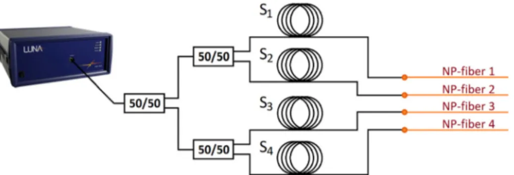
in the ithline, respectively. Because the backscattering power from the NP-doped fiber is several dB higher with respect to the one generated by the SMF-28 separators (roughly 40 dB more), the trace of the NP-doped fiber can be distinguished and properly correlated by the OBR, while the backscattering coming from the other SMF-28 fibers can be treated as a noise. This method is robust and scalable. The NP-doped fiber behaves like a standard fiber in terms of sensitivity to temperature and strain with the only difference given by the enhanced backscattering [36]. The level of backscattering is high with respect to a standard SMF-28 but low enough to preserve the validity of the operating principles of the OFDR. Moreover, the capability of scaling the number of multiplexed fibers depends mainly on the sensor length. Beisenova et al. reported OBR multiplexing with 4 temperature sensing fibers, with potential multiplexing of up to 32 sensors by reducing the sensor length to 6 cm [33], a length more than reasonable for high precision bio-medical applications [7,37]. An example of multiplexed setup is shown in the schematic of Fig.1.
The schematic shows a parallel of 4 fibers, where the parallel is obtained by using 3 splitters 1×2 in cascade. Four separators Si, each of them presenting a different length, are spliced to
Fig. 1. Schematic of 4 lines multiplexed setup. Each line is composed by a SMF-28
separator spliced to a cut of NP-doped fiber. The length of each separator is calibrated to permit the NP-doped fiber of one line to overlap only the separators of the other lines.
a cut of NP-doped fiber. The shown schematic is the base of the setup used in this work to reconstruct the 3D shape of an epidural needle during the insertion in a proper phantom. Cuts of 18 cm of NP-doped fibers have been fixed to an epidural needle in order to detect the strain in 4 different directions. The OBR used is the commercial Luna Inc., OBR4600 [31]. The advantage of this parallel setup is given by the possibility of achieving a simultaneous distributed sensing on each branch, according to the operating principles of OFDR [30], by multiplexing the sources of distributed sensing in space. This is a significant improvement with respect to other methods based on time polling of each sensor by using a switch [32], in particular in real-time continuous operation. Actually, the OBR, because of the complexity of internal operations, to trigger and reference the input signal and to reconstruct the spectrum in each sensing point, cannot achieve a high frequency time sampling (usually something in between 1 to 5 Hz). A time polling by means of a switch would drastically reduce the frequency of interrogations in time to values much lower of 1 Hz, since each channel has to be triggered and referenced separately. The proposed simultaneous spatial multiplexing strategy, instead, preserves the capability of continuous operation given by the OBR. Another advantage presented by this kind of multiplexed setup is given by the possibility of pack a number of sensors in a limited space, a typical requirement in bio-medical and surgical devices such as needles and catheters [5]. 2.2. MgO based nanoparticle fiber
As previously explained, the most important component of the simultaneous spatial multiplexed setup, which permits the correct detection by the OBR, is the MgO nanoparticle doped fiber. The use of such fiber is an elegant solution with respect to fibers which are UV-processed to increase the scattering properties [32]. The nanoparticle doped fiber, after the preform fabrication, can be drawn in meters-long spool, where every section of the fiber presents similar, form the statistical point of view, scattering properties. This permits to treat the special fiber as a standard fiber by cutting and splicing the desired length for the sensor application.
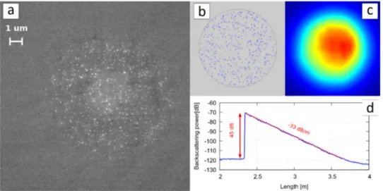
The fiber cross-section is shown in Fig.2(a). The fiber presents the typical size of a telecom fiber, having the core diameter of 10 µm and the cladding diameter of 125 µm. It is worth noting that the standard size permits the fiber to be easily spliced with ordinary SMF-28 pigtails. The original purpose of the fiber is to be an optical amplifier in the telecom C-band with enhanced efficiency, so that the core of the fiber is doped with Er3+and MgO-based nanoparticles. The presence of the nanoparticles permits to create a more suitable environment to improve the property of optical amplification of erbium ions. However, in this work, the amplifier properties of the fiber have not been exploited. Instead, the focus has been put on the nanoparticles distributed in the core and the strong increment of backscattering induced by their presence. The
nanoparticle distribution is random, as well as their size, which varies from 20 nm to 100 nm. The composition of the nanoparticles is dependent on the phase separation of MgO in the buffer of silica, so the nanoparticles are silica enriched of MgO.
Fig. 2. (a) SEM of the NP-doped fiber; (b) realization of a random generated structure used
for FEM simulations; (c) fundamental mode field distribution; (d) backscattering power vs fiber length.
This special optical fiber preform is fabricated with conventional Modified Chemical Vapor Deposition (MCVD) technique [38]. The high temperature reached during the process allows to form oxide nanoparticles in germanium-doped silica-based preforms. The principle, that permits the nanoparticle to be created, is the spontaneous phase separation process, i.e. the immiscibility between alkaline ions and silicate systems [39]. In the presented fiber, the phase separation creates two phases: one rich of silica and one rich of MgO, condensed to form spherical nanoparticles, whose characteristics depend on the initial concentration of Mg. The final composition of the preform is difficult to estimate. Energy Dispersive X-ray (EDX) analyses suggests that magnesium and germanium concentrations vary along the axial direction of the fiber. The exact composition of the nanoparticles is also difficult to estimate. The strong scattering in the core preform impedes the experimental measurement of the core refractive index using a standard preform analyzer. Nevertheless, based on the averaged concentration of germanium and magnesium, the refractive index of the core substrate can be estimated to a value varying from 1.7 to 4.0×10⁻³higher with respect to the cladding index, while the refractive index of the nanoparticles ranges from 1.53 to 1.65 [34].
Using those estimated data, related to the refractive indices of the material and the distribution of the nanoparticles, a set of random generated structures, which share the same statistics of the real fiber cross-section shown in Fig.2(a), have been numerically analyzed by means of a Finite Element Method (FEM) based software. An example of random realization of fiber cross-section is shown in Fig.2(b). The simulations permit to depict a scenario characterized by a multimode behavior. The shape of the modes is deformed by the effect of the localization given by the nanoparticles random pattern [40], as shown in Fig.2(c), where the fundamental mode (FM) is depicted. The calculated average Mode Field Diameter (MFD) of the fundamental mode is 9.7 µm at 1550 nm, roughly 2 µm smaller than the MFD of a fiber presenting the same core diameter and index contrast between core and cladding, but without nanoparticles.
The presence of nanoparticles not only induces a higher scattering, but also modifies the propagation behavior of the fiber. The fiber backscattering has been investigated by using Luna
OBR4600. A long cut NP-doped fiber has been spliced to a SMF-28 pigtail feed the OBR. The OBR spatial resolution has been chosen of 0.1 mm. Performing a Fourier analysis of the backscattered signal, tested by an input laser scanning from 1530 nm to 1572 nm, the OBR is able to reconstruct the backscattered power along the fiber length, as it is shown in Fig.2(d). The backscattering of the SMF-28 pigtail, just before the splice, presents a level of -118 dB. After the splice, the NP-doped fiber shows a backscattering power which is roughly 45 dB higher. The backscattering level rapidly decrease with a rate of 33 dB/m, falling under the detectable level after 1.5 meter of NP-doped fiber. The high backscattering and the attenuation are mainly given by the presence of nanoparticles. A second source of attenuation can be identified by the presence, in the fiber core, of erbium, which is an optical active material in the region of operation of the OBR. However, the concentration of erbium (1.5 × 1024ions/m3) is to be considered low.
At this concentration, the backscattering given by the erbium ions has been measured to be lower than 0.7 dB/m, negligible with respect to the backscattering given by the nanoparticles.
3. Experimental setup
In order to exploit the distributed spatial multiplexed paradigm for 3D shaping, an experimental setup has been prepared. The setup is divided in three main parts: an OBR, a fiber parallel composed by cuts of SMF-28 pigtails and cuts of NP-doped fiber arranged as explained in the previous section, and an epidural needle, which is the target of the shape sensing, properly sensorized with the fiber parallel.
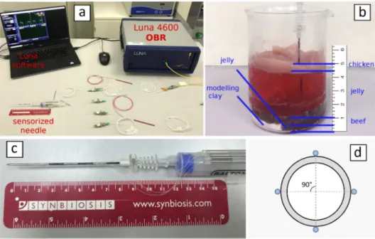
The core of the distributed sensing measurements setup is based on a commercial OBR (Luna Inc., OBR4600) [31], shown in Fig.3(a), that operates according to the principles of OFDR. Thanks to this powerful device it is possible to detect the Rayleigh backscattering spectrum along the sensor, usually represented by a standard SMF-28 fiber.
Fig. 3. (a) Experimental setup; (b) detail of the phantom used for the insertions; (c) detail of
the sensorized epidural needle; (d) schematic of the needle cross-section, it is worth noting that the fiber are placed at 90° with respect to each other along x and y directions.
The backscattering trace of a fiber acts like a distributed signature. In fact, the backscattering spectrum shifts when the sensor experiences a change of temperature or strain. This shift
can be correlated to the original trace in order to detect point by point temperature and strain variation. While standard and cheap SMF-28 can become an effective distributed sensor, the cost is paid in term of complicated and time-consuming operation of Fast Fourier transform performed by the OBR. Because of that, the choice of the sensing parameters is fundamental and represents a trade-off between spatial resolution, strain accuracy and sampling frequency in real-time continuous measurement. The instrument parameters have been selected as following: the sensing range has been set to 1 m covering the fiber parallel cut that includes the NP-doped particles; the gauge length, which represents the calculation window size where the operation of cross-correlation is performed, is set to 0.5 cm; and the sensor spacing has been chosen to 0.2 cm.
The fibers parallels, whose operating principles have been explained in the previous section, is composed by 4 lines made by a SMF-28 separator, spliced with a cut of high scattering NP-doped fiber. The splice has been easily performed with the entry level fusion splicer (Fujikura 12-S), by setting the single mode (SM to SM) program, thanks to the standard telecom dimension of the NP-doped fiber. The length of the separators has been properly chosen in order to impede the spatial overlap between two NP-doped fibers. The length of the NP-doped fiber cut has been set to roughly 17-18 cm. Each line of the parallel has been connected by the help of three 50/50 1×2 splitters. The input of the first splitter has been connected to the OBR, while the NP-doped fiber terminations have been fixed by the use of the epoxy glue to epidural needle, as shown in Fig.3(c). The needle is a Tuohy epidural needle (ZZOR18G model), presenting 8 cm of length, 18 Gage of thickness equivalent to 1.32 mm of outer diameter and 1.09 mm of inner diameter, produced by Balton (Poland). The fibers have been arranged on the needle following two perpendicular directions, namely x and y, with two fibers in every direction, so than the angle between neighbor fibers is 90°, as depicted in the schematic of Fig.3(d). Not all the needle length has been sensorized, the fibers have been glued only in the last 7 cm of the needle starting from the tip. To verify the correct operation of the spatial multiplexed setup and the correct spacing between the fiber separators the backscattering trace has been measured by the OBR. The trace is shown in Fig.4.
Fig. 4. Backscattering trace of spatial multiplexed fiber setup. Each NP-doped fiber cut
is roughly 17–18 cm. The length of the separators has been selected to avoid the overlap between the NP-doped fiber trace.
Furthermore, to test the setup for 3D shape sensing, a phantom, created to reproduce the bio-tissues and the ligaments that the needle shall pass through to achieve the epidural space, has been used. The phantom, depicted in Fig.3(b), is similar to the one proposed by Beisenova et
or ligament. It is equipped with a layer of hardened clay to simulate the contact of the needle tip with the spinal bones, when the epidural space is not correctly achieved. The goal of the phantom, for this application, is to give to the sensorized needle a realistic route of insertion, such that the spatial multiplexed could sense the strain on x and y directions. Starting from the strain, the shape of the needle during the insertion is reconstructed.
4. Results and discussion
4.1. Reconstruction of 3D shape
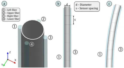
As shown in Fig.5, four fibers are fixed along the length of the needle. The fibers are coupled, so that two sense the strain in a perpendicular direction, namely ˆx for the fibers 1 and 3, ˆy for the fibers 2 and 4. The strain is, therefore, decomposed in two perpendicular components Sxand Sy. This
configuration permits to have an effective strain detection and, at the same time, a compensation of temperature change along the z axis. Moreover, the configuration with four fibers, orthogonally disposed, permits a simplified bending reconstruction [41]. In normal condition, under the hypothesis that the needle can be bent but not deformed in its transversal cross-section, the fibers coupled on a particular axis will experience a strain that is equal in modulus and opposite in sign. The potential difference can be induced by a gradient of temperature, which can be removed since all the fibers, in fixed a position z, should experience the same temperature. In the condition of straight needle, every fiber detects the strain on the needle in distributed points spaced by s, which is the sensor spacing set in the OBR, in the case under exam 2 mm. Therefore, the needle can be divided in small cylinders of height s. When the needle is bent in a random direction, the strain induced by the bending can be decomposed along the ˆx and ˆy directions, and the respective fiber couple can detect the strain variation, which represents a deformation of the cylinder of height s.
Fig. 5. (a) Position and nomenclature of the fibers fixed along the length of the epidural
needle; (b) every couple of fiber (1,3 and 2,4) monitors the strain on a perpendicular direction, the strain is calculated every fiber portion long s; (c) The fiber portion is deformed inducing the overall bend.
To reconstruct the shape of the needle by using the strain measurements, it is possible to use the following iterative algorithm:
• The normal ˆni+1of the cylinder Ci+1depends on the strain applied to the cylinder Ci, in
particular the normal ˆni+1is rotated in the plane xz and yz by the following angles:
θx,i+1= tan−1 h (Sx,i,3− Sx,i,1) s d i (3) θy,i+1= tan−1 h (Sy,i,4− Sy,i,2) s d i (4) Knowing the rotation angle at every step it is possible to reconstruct the direction of the normal vector step by step. Consequently, it is possible to locate the center of the needle and its shape for every step ∆z equivalent to the sensor spacing s. This method represents a local linear approximation of the bending induced in the needle, which is valid for bending of small entity (in this work, the maximum displacement is ∼1.5 mm over 80 mm, corresponding to maximum bending angle ∼1°). However, in many bio-medical applications, such as micro-invasive robotic surgery, a very small shape deformation has to be detected and reconstructed. This method, combined to the relevant strain sensitivity given by the use of optical fibers, is well suitable for this kind of applications.
4.2. Straightforward insertion
The first experiment has been performed by inserting the needle, equipped with the parallel setup of sensors, in the phantom shown in Fig.3(d). Every insertion has been manually performed by slowly puncturing each layer of the phantom, along a straight line, to reach the epidural space represented by the last jelly layer.
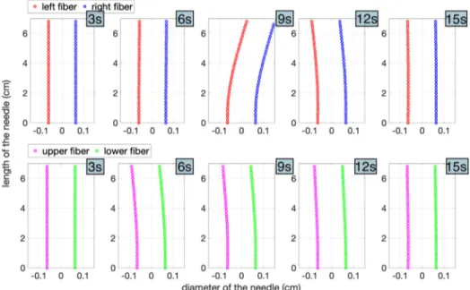
The experiment has been repeated several times to verify the repeatability of the procedure and to verify the consistency of the proposed 3D shaping method. In Fig.6the results of one experiment are shown. The displacement of fiber 1 and fiber 3 along x axis has been plotted in the upper line for five different moments of time, while the displacement of fiber 2 and fiber 4 along
Fig. 6. Straightforward insertion. Displacement of fiber 1 (red) and fiber 3 (blue), for
different time moments, are shown in the upper sequence; Displacement of fiber 2 (magenta) and fiber 4 (green), for the same time moments, are shown in the lower sequence.
yaxis has been plotted, for the same moments of time, in the lower line. The time of penetration is roughly 15 seconds. It is possible to notice that the needle, penetrating in the phantom and passing through different layers with different stiffness, experiences bending, that can rotate along the axis. In fact, the components of the displacement, reconstructed by the strain measurement using the strategy explained in the previous sub-section, show a change of direction during the penetration. Furthermore, the picture shows that the maximum angle of bending is obtained at 5 cm from the tip of the needle, while the tip remains mostly straight. When the last layer of jelly that represents the epidural space is reached, the strain is released, and the needle return in its original straight shape. The couples of fibers along x and y axes follow the same pattern, so that it is comfortable to reconstruct the shape of the needle, since one fiber shows a positive strain while the opposite one shows the same strain but negative. It is worth noting that the total bending is small, i.e. less than 2 mm along the length of the needle that is sensorized (7 cm).
The proposed system operates very well when the bending to sense in small, since the sensitivity of the fiber to detect the strain is quite relevant. This behaviour also justifies the assumption of small bending that has been used in the algorithm for shape sensing.
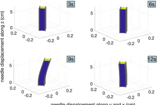
Starting from the components of the displacement it is possible to reconstruct the spatial modification of needle shape during the penetration, and plot it in a 3D reference, as shown in Fig.7, or create an animation (seeVisualization 1andVisualization 2). The frame rate of the animation is one frame per second. This value is the value suggested by the OBR when 1 m of fiber is detected and 2 mm of sensing space are set, operating in continuous mode.
Fig. 7. Straightforward insertion. 3D shape reconstruction of the needle during the
penetration at different time moments. The animation can be retrieved here (Visualization 1). It is worth noting that the x and y axes are scaled by a factor of ten. The 3D shape with realistic size is here (Visualization 2).
The frequency rate can be improved by reducing the length of NP-doped fiber, so that the sensing length of 1 m can be reduced too. Moreover, the frequency of the OBR can be further adjusted by operating on the setting of the instrument.
4.3. Insertion with bone collision
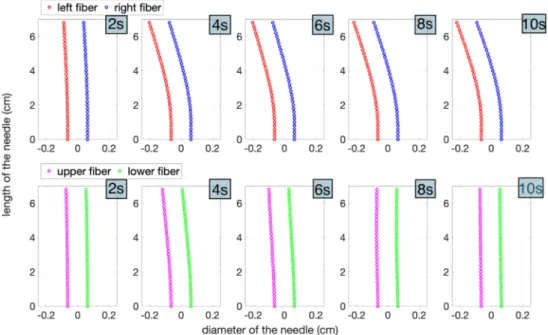
The second set of experiments has been performed inserting the needle inside the phantom to simulate a collision with a bone. Form Fig.3, it can be seen that the bottom layer of the phantom is divided in two part, a soft jelly part that mimics the epidural space and a hardened clay that represent a bone. The penetration has been manually performed and a little bit of pressure has been applied when the clay has been reached. The results of experiment are shown in Fig.8. As the previous case, it is possible to see the displacement of fiber 1 and fiber 3 along x axis in the upper sequence, and the displacement of fiber 2 and fiber 4 along y axis in the lower sequence. The time of penetration, in this case, is 10 seconds and the pictures has been plotted with a time increment of 2 seconds. Respect to the straightforward insertion, now the needle experiences an extra bending because of the collision with the clay. In the last time frame the residual bending is correctly recorded by the OBR and reconstructed in the 3D shape.
Fig. 8. Insertion with bone collision. Displacement of fiber 1 (red) and fiber 3 (blue), for
different time moments, are shown in the upper sequence; Displacement of fiber 2 (magenta) and fiber 4 (green), for the same time moments, are shown in the lower sequence.
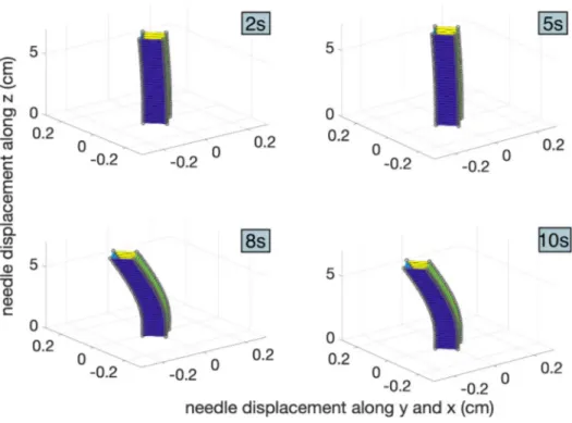
Four frames of the 3D shape reconstruction, representing different moments of the penetration, are shown in Fig.9, the corresponding animations can be retrieved here (Visualization 3). The frame rate of the animation is one frame per second. The x and y axes of the 3D animation are scaled by ten, to permit the visualization of the small bending. The proposed system has been demonstrated to be well suitable to detect such a small needle deformation. The real-scale needle shape reconstruction can be seen here (Visualization 4).
Fig. 9. Insertion with bone collision. 3D shape reconstruction of the needle during the
penetration at different time moments. The animation can be retrieved here (Visualization 3). It is worth noting that the x and y axes are scaled by a factor of ten. The 3D shape with realistic size is here (Visualization 4).
5. Conclusion
In this work a novel method of 3D shape sensing, mainly for medical devices such as needles and catheters, has been reported. The proposed 3D shape sensing is particularly effective when a small deformation needs to be detected. Such situations are common in several bio-medical applications like micro-invasive robotic surgery or ophthalmic procedures. The described system is based on the use of a new paradigm of simultaneous distributed spatial multiplexing of optical fiber sensors. A parallel of special optical fibers has been designed to feed an OBR to detect temperature or strain. Each line of the parallel is built by splicing a telecom SMF-28 pigtail and a custom made MgO-based NP doped fiber. Thanks to the involved fabrication technology, this fiber presents a core sprinkled by a random pattern of MgO nanoparticles having a diameter in between 20 nm and 100 nm. The effect of the nanoparticles is to increase the level of scattering. The detected backscattering is more than 40 dB larger than the one shown by a standard telecom fiber. Therefore, by building the fiber parallel in a way that the NP-doped fiber does not overlap with the other NP-doped fiber on the other lines, it is possible to distinguish the NP-doped fiber high backscattering from the low-level backscattering of the SMF-28 pigtails. The amount of SMF-28 backscattering can be mathematically treated like a noise with respect to the NP-doped fiber backscattering. This setup is effective, non only for distributed sensing of different fibers, but it is also effective in real-time operation, since it does not involve time polling, detrimental for OBR operation. The proposed paradigm of simultaneous distributed multiplexing represents a novel solution in the area of fiber sensors, being able to combine parallel spatial multiplexing, distributed sensing, and real-time operation. This permits the efficient parallel operation of the OBR, which is usually fed by a single sensor. The adopted solution, involving the nanoparticle doped fiber, is scalable in terms of number of multiplexed channels. Moreover, the nanoparticles
doped fiber, after the fabrication of the preform, represents a cost-effective practical solution with advantages in terms of reliability.
The proof of the proposed 3D shape sensing methodology has been done by using a Tuohy epidural needle. The parallel of optical fiber has been glued along the length of the needle with an arrangement that involves the fibers to be coupled along x and y axis directions. Every fiber is separated by its neighbors by an angle of 90°. This geometry permits the detection of two perpendicular stain components. With the precise strain information, given by the OBR, it is possible to reconstruct the bending along the needle, and consequently the 3Ds shape. A locally linear approximation of the bending, valid for small deformation, has been applied to reconstruct the shape form the strain components. Two kind of insertion experiments, namely a straightforward insertion and a collision against a bone, have been manually performed using a special custom-made phantom able to simulate the spine anatomy of the epidural space. Results have shown the effective capability of sensing the strain form the fiber parallel and reconstructing the bending and the real-time evolution of the 3D shape of the needle. The detected shape has been demonstrated to effectively describe the expected behavior of the needle, penetrating the phantom according to well recognizable insertion patterns.
Funding
ORAU program at Nazarbayev University (grants FOSTHER 2018-2020); Agence Nationale de la Recherche (ANR) (ANR-17-CE08-0002).
Acknowledgments
The authors acknowledge S. Trzesien and M. Ude (INPHYNI, Nice, France) for the fabrication of the fiber.
References
1. M. Amanzadeh, S. M. Aminossadati, M. S. Kizil, and A. D. Rakić, “Recent developments in fibre optic shape sensing,”Measurement128, 119–137 (2018).
2. A. Plamondon, A. Delisle, C. Larue, D. Brouillette, D. McFadden, P. Desjardins, and C. Larivière, “Evaluation of a hybrid system for three-dimensional measurement of trunk posture in motion,”Appl. Ergonomics38(6), 697–712 (2007).
3. W. Y. Wong and M. S. Wong, “Detecting spinal posture change in sitting positions with tri-axial accelerometers,” Gait & Posture27(1), 168–171 (2008).
4. D. Tosi, E. Schena, C. Molardi, and S. Korganbayev, “Fiber optic sensors for sub-centimeter spatially resolved measurements: Review and biomedical applications,”Opt. Fiber Technol.43, 6–19 (2018).
5. F. Khan, A. Denasi, D. Barrera, J. Madrigal, S. Sales, and S. Misra, “Multi-core Optical Fibers with Bragg Gratings as Shape Sensor for Flexible Medical Instruments,”IEEE Sens. J.19(14), 5878–5884 (2019).
6. Y. Park, S. Elayaperumal, B. Daniel, S. C. Ryu, M. Shin, J. Savall, R. J. Black, B. Moslehi, and M. R. Cutkosky, “Real-Time Estimation of 3-D Needle Shape and Deflection for MRI-Guided Interventions,”IEEE/ASME Trans. Mechatron.15(6), 906–915 (2010).
7. B. Gonenc, J. Chae, P. Gehlbach, H. R. Taylor, and I. Iordachita, “Towards Robot-Assisted Retinal Vein Cannulation: A Motorized Force-Sensing Microneedle Integrated with a Handheld Micromanipulator,”Sensors17(10), 2195 (2017).
8. K. Mandal, F. Parent, S. Martel, R. Kashyap, and S. Kadoury, “Vessel-based registration of an optical shape sensing catheter for MR navigation,”Int. J. CARS11(6), 1025–1034 (2016).
9. B. Lee, “Review of the present status of optical fiber sensors,”Opt. Fiber Technol.9(2), 57–79 (2003).
10. E. Udd and W. B. Spillman Jr., Fiber optic sensors: an introduction for engineers and scientists (John Wiley & Sons, 2011).
11. Biological Evaluation of Medical Devices, ISO 10993, International Organization for Standardization: Geneva, Switzerland, 1995.
12. C. Waltermann, J. Koch, M. Angelmahr, J. Burgmeier, M. Thiel, and W. Schade, “Fiber-Optical 3D Shape Sensing,” in Planar Waveguides and other Confined Geometries. Springer Series in Optical Sciences, G. Marowsky, ed. (Springer, 2015).
13. F. Pena, L. Richards, A. R. Parker Jr., A. Piazza, P. Chan, and P. Hamory, “Fiber Optic Sensing System (FOSS) technology-A new sensor paradigm for comprehensive structural monitoring and model validation throughout the vehicle life-cycle,” (2015).https://www.nasa.gov/sites/default/files/atoms/files/dr-0001-lst-016-foss-4pgr-online.pdf
14. G. Schiffner, “Sensing device having a multicore optical fiber as a sensing element,” (US Patent 4443698A, 1984). https://patents.google.com/patent/US4443698
15. N. Lagakos, J. H. Cole, and J. A. Bucaro, “Microbend fiber-optic sensor,”Appl. Opt.26(11), 2171–2180 (1987). 16. W. W. Morey, G. Meltz, and W. H. Glenn, “Fiber Optic Bragg Grating Sensors,”Proc. SPIE1169, 98–107 (1990). 17. Y. J. Rao, “Recent progress in applications of in-fibre Bragg grating sensors,”Opt. Lasers Eng.31(4), 297–324
(1999).
18. T. Erdogan, “Fiber grating spectra,”J. Lightwave Technol.15(8), 1277–1294 (1997).
19. M. A. Davis, A. D. Kersey, J. Sirkis, and E. J. Friebele, “Shape and vibration mode sensing using a fiber optic Bragg grating array,”Smart Mater. Struct.5(6), 759–765 (1996).
20. G. M. H. Flockhart, W. N. MacPherson, J. S. Barton, J. D. C. Jones, L. Zhang, and I. Bennion, “Two-axis bend measurement with Bragg gratings in multicore optical fiber,”Opt. Lett.28(6), 387–389 (2003).
21. G. A. Miller, C. G. Askins, and E. J. Friebele, “Shape sensing using distributed fiber optic strain measurements,” Proc. SPIE5502, 528–531 (2004).
22. R. J. Roesthuis, M. Kemp, J. J. van den Dobbelsteen, and S. Misra, “Three-Dimensional Needle Shape Reconstruction Using an Array of Fiber Bragg Grating Sensors,”IEEE/ASME Trans. Mechatron.19(4), 1115–1126 (2014). 23. A. Derkevorkian, S. F. Masri, J. Alvarenga, H. Boussalis, J. Bakalyar, and W. L. Richards, “Strain-based deformation
shape-estimation algorithm for control and monitoring applications,”AIAA J.51(9), 2231–2240 (2013). 24. C. G. Askins, G. A. Miller, and E. J. Friebele, “Bend and Twist Sensing in a Multiple-Core Optical Fiber,” in Optical
Fiber Communication Conference/National Fiber Optic Engineers Conference, OSA Technical Digest(Optical Society of America, 2008), paper OMT3.
25. I. Floris, P. A. Calderón, S. Sales, and J. M. Adam, “Effects of core position uncertainty on optical shape sensor accuracy,”Measurement139, 21–33 (2019).
26. I. Floris, S. Sales, P. A. Calderón, and J. M. Adam, “Measurement uncertainty of multicore optical fiber sensors used to sense curvature and bending direction,”Measurement132, 35–46 (2019).
27. M. K. Tsilimbaris, E. S. Lit, and D. J. D’Amico, “Retinal Microvascular Surgery: A Feasibility Study,”Invest. Ophthalmol. Visual Sci.45(6), 1963–1968 (2004).
28. X. Bao and L. Chen, “Recent Progress in Distributed Fiber Optic Sensors,”Sensors12(7), 8601–8639 (2012). 29. M. Froggatt, “Distributed measurement of the complex modulation of a photoinduced Bragg grating in an optical
fiber,”Appl. Opt.35(25), 5162–5164 (1996).
30. M. Froggatt and J. Moore, “High-spatial-resolution distributed strain measurement in optical fiber with Rayleigh scatter,”Appl. Opt.37(10), 1735–1740 (1998).
31. Luna technologies, OBR 4600, [Online]. Available:http://lunainc.com/product/sensing-solutions/obr-4600/ 32. F. Parent, S. Loranger, K. K. Mandal, V. L. Iezzi, J. Lapointe, J. S. Boisvert, M. D. Baiad, S. Kadoury, and R. Kashyap,
“Enhancement of accuracy in shape sensing of surgical needles using optical frequency domain reflectometry in optical fibers,”Biomed. Opt. Express8(4), 2210–2221 (2017).
33. A. Beisenova, A. Issatayeva, S. Sovetov, S. Korganbayev, M. Jelbuldina, Z. Ashikbayeva, W. Blanc, E. Schena, S. Sales, C. Molardi, and D. Tosi, “Multi-fiber distributed thermal profiling of minimally invasive thermal ablation with scattering-level multiplexing in MgO-doped fibers,”Biomed. Opt. Express10(3), 1282–1296 (2019).
34. W. Blanc, V. Mauroy, L. Nguyen, B. N. Shivakiran Bhaktha, P. Sebbah, B. P. Pal, and B. Dussardier, “Fabrication of Rare Earth-Doped Transparent Glass Ceramic Optical Fibers by Modified Chemical Vapor Deposition,”J. Am. Ceram. Soc.94(8), 2315–2318 (2011).
35. A. Beisenova, A. Issatayeva, D. Tosi, and C. Molardi, “Fiber-Optic Distributed Strain Sensing Needle for Real-Time Guidance in Epidural Anesthesia,”IEEE Sens. J.18(19), 8034–8044 (2018).
36. C. Molardi, S. Korganbayev, W. Blanc, and D. Tosi, “Characterization of a nanoparticles-doped optical fiber by the use of optical backscatter reflectometry,”Proc. SPIE10821, 1082121 (2018).
37. X. He, J. Handa, P. Gehlbach, R. Taylor, and I. Iordachita, “A submillimetric 3-DOF force sensing instrument with integrated fiber Bragg grating for retinal microsurgery,”IEEE Trans. Biomed. Eng.61(2), 522–534 (2014). 38. W. Blanc and B. Dussardier, “Formation and applications of nanoparticles in silica optical fibers,”J. Opt.45(3),
247–254 (2016).
39. J. B. Mac Chesney, P. B. Oapos Connor, and H. M. Presby, “A new Technique for the Preparation of low-Loss and Graded-Index Optical Fibers,”Proc. IEEE62(9), 1280–1281 (1974).
40. B. Abaie, E. Mobini, S. Karbasi, T. Hawkins, J. Ballato, and A. Mafi, “Random lasing in an Anderson localizing optical fiber,”Light: Sci. Appl.6(8), e17041 (2017).
41. J. Yi, X. Zhu, H. Zhang, L. Shen, and X. Qiao, “Spatial shape reconstruction using orthogonal fiber Bragg grating sensor array,”Mechatronics22(6), 679–687 (2012).