HAL Id: hal-00339457
https://hal.archives-ouvertes.fr/hal-00339457
Submitted on 17 Sep 2009
HAL is a multi-disciplinary open access
archive for the deposit and dissemination of
sci-entific research documents, whether they are
pub-lished or not. The documents may come from
teaching and research institutions in France or
abroad, or from public or private research centers.
L’archive ouverte pluridisciplinaire HAL, est
destinée au dépôt et à la diffusion de documents
scientifiques de niveau recherche, publiés ou non,
émanant des établissements d’enseignement et de
recherche français ou étrangers, des laboratoires
publics ou privés.
AMRA: Augmented Reality Assistance for Train
Maintenance Tasks
Jean-Yves Didier, David Roussel, Malik Mallem, Samir Otmane, Sylvie
Naudet, Quoc-Cuong Pham, Steve Bourgeois, Christine Mégard, Christophe
Leroux, Arnaud Hocquard
To cite this version:
Jean-Yves Didier, David Roussel, Malik Mallem, Samir Otmane, Sylvie Naudet, et al.. AMRA:
Augmented Reality Assistance for Train Maintenance Tasks. Workshop Industrial Augmented Reality,
4th ACM/IEEE International Symposium on Mixed and Augmented Reality (ISMAR 2005), Oct 2005,
Vienna, Austria. pp.(Elect. Proc.). �hal-00339457�
AMRA: Augmented Reality assistance in train maintenance tasks
Jean-Yves Didier
David Roussel
Malik Mallem
Samir Otmane
Laboratoire Syst`emes Complexes - Universit´e d’Evry
40, rue du Pelvoux - 91000 Evry - FRANCE
{didier, roussel, mallem, otmane}@iup.univ-evry.fr
Sylvie Naudet
Quoc-Cuong Pham
Steve Bourgeois
Commissariat `a l’ ´
Energie Atomique (CEA) - CEA/LIST/SARC
CEN SACLAY - 91191 Saclay - FRANCE
{sylvie.naudet, quoc-cuong.pham, steve.bourgeois}@cea.fr
Christine M´egard
Christophe Leroux
CEA/LIST/SCRI - CEN FAR BP 6
92265 Fontenay-aux-Roses - FRANCE
{christine.megard, christophe.leroux}@cea.fr
Arnaud Hocquard
Alstom Transport
23-25 Avenue Morane Saulnier
92364 Meudon la Forˆet Cedex - FRANCE
[email protected]
Abstract
The AMRA project, carried out by a consortium including industrials and research partners, aims at implementing an Augmented Reality (AR) system for mobile use in industrial applications such as train maintenance and repairs in in-dustrial sites. The adopted solution is a video see-through system where a tablet-PC is used as an augmented window. The overall architecture of a prototype is unfolded, and its key points are detailed. For instance, a visual registration system has been developed to accurately overlay a video stream with information. A robust, real time registration, using a single camera tied to the tablet-PC, is performed. Besides, a hierarchical description of maintenance proce-dure is set up and enriched by new media such as photos, video and/or 3D models. These 3D models have been spe-cially tailored to meet maintenance tasks requirements. The obtained multimedia contents allow easy access to techni-cal documentation through a man machine interface man-aging a multimedia engine. All these features have been combined in the AMRA prototype which have been evalu-ated by a maintenance operator.
Keywords: augmented reality, registration, real-time
ob-ject tracking, man-machine interface, industrial mainte-nance
1. Introduction
The AMRA project, sponsored by the French Ministry of Research, is carried out by a consortium of partners includ-ing industrials and research labs. This project aimed at im-plementing an Augmented Reality system for mobile use in industrial applications, especially train maintenance. There were two objectives for such a system: the first of them was to transform cumbersome paper technical manu-als to an electronic multimedia document allowing an eas-ier data browsing. The second objective was to provide an helper application which could provide assistance and shorten the training course of a new-comer maintainer on real devices.
A video see-through system was developed, based on a tablet-PC used as an augmented window on the real world. This kind of systems raises some challenging issues such as: mobile computing, real-time object/camera registration, and contextual graphic help.
Since Augmented Reality involves field experimentations, an architecture has to be defined for sharing resources and data streams between mobile computer (on a tablet-PC) and remote computer(s) hosting maintenance database and heavy computing algorithms as detailed in section 3. Among the critical tasks of mobile Augmented Reality ap-pears the registration, since there is relative motion
be-tween the device and the tracked objects. These ones should be temporally and accurately registered. To overlay video streams with contextual information, a robust, real time reg-istration system using a single camera tightly attached to the tablet-PC is introduced in section 4.
The AMRA system should provide contextual help during the execution of a maintenance procedure. Thus, an elec-tronic description of a maintenance procedure have been de-signed as a structured document, enhanced with new media in addition to the textual instructions. Such an intuitive ac-cess is made available through a multimedia engine which allows to bring a contextual help at each step of the mainte-nance procedure as explained in section 5.
All these developments have been put together in the AMRA prototype and which is controlled through a Man machine Interface. This interface and its evaluation by a expert operator is detailed in section 6.
2. Related work
Many AR applications have, in the past, focused on the field of training and maintenance. One of the first demonstrator of AR technology was developed for Boeing for wire bundle assembly support [7]. The final prototype wass composed, as far as we know, of an HMD (Head Mounted Display) as a display device and using magnetic sensors for tracking. Using very simple graphics, the operator was shown where he had to put the wires.
Another early demonstrator of AR technology was designed for a maintenance task on a photocopier [11]. The devices used in this case were a monochrome monoscopic HMD for visualization and ultrasonic sensors for objects tracking. The graphics used were simplified wireframe 3d models, not related to the CAD (Computer Assisted Design) mod-els.
This application was followed by another one in the con-struction area [23] where the system was intended to help assembling spaceframe structures. An active optical track-ing system composed of blinktrack-ing LEDs was coupled to a passive inertial system. Once again, this system was us-ing simple graphics. The next assembly part was identified (tagged with a conventional barcode) with an optical bar-code reader.
The Fraunhofer IGD also developed an AR demonstrator for BMW. The selected task was a door-lock assembly into a car door [16]. CAD data issued from the design of the actual objects were used. Optical tracking have been cho-sen to localize the door, which was achieved by the mean of square targets forming a coded pattern. The visualization system was composed of an optical see-through HMD. In the same maintenance scope using AR, a demonstrator was developed for nuclear powerplants maintenance [14].
This application focused mainly on the aspects of the in-formations streams for applications built on large database which couldn’t fit within mobile devices such as a laptop. The system was using a HMD to display augmented infor-mations and also a flat LCD screen as a complementary information source. Tracking technology was optical and consisted in locating black circles targets in the environ-ment.
More recently, during four years (from 1999 to 2003), the co-ordinating German project ARVIKA [2] aimed at re-alizing AR-Technologies to support development, produc-tion and servicing (which also covers the maintenance as-pects) with relation to complex technical products in a user-oriented and application driven manner. This project was involving more than twenty partners including research lab-oratories, car and aircraft manufacturers. Such project is showing the growing interest of industry and manufacturers in the AR technologies.
3. Overall architecture of the system
The first architectural choice was to determine which kind of sensors and which display we should use for our aug-mented reality application. We first thought to use head mounted displays (HMD) but this choice was discarded for several reasons:
• In the case of a video or optical see-through HMD we
had to choose between cheap devices with a very nar-row horizontal field of view (less than 30 degrees in most of the case) or expensive HMD with large field of view that were considered too bulky for our appli-cation,
• Positions of maintenance operators sometimes do not
allow them to comfortably wear HMD,
• And finally, a field study revealed that maintenance
op-erators did not want to wear any kind of HMD. A tablet-PC was chosen as a display device (see figure 1) acting as an augmented window of the real world. Indeed, this kind of device is much lighter than classical laptops. Using this kind of display, the tracking device we selected was a camera. Real world was equipped with targets that would help recovering camera pose using image processing as explained in section 4.
At the time project started in year 2002, tablet-PC did not have enough computation power to display mixed vir-tual/real graphics and achieve image processing algorithm on the same CPU. The architecture exposed in figure 2 involved a remote server handling datastreams and heavy computations needed for registration.
Camera
touchscreenwith its Tablet−PC
Stylus pen
Figure 1. Tablet-PC (on the right) and tablet-PC with its camera (on the left).
be shared between different users which means we cannot store it in the operator’s maintenance tablet-PC.
The camera is tightened to the tablet-PC and connected to the remote computer through a IEEE1394 link (which has to be replaced by a radio link in order to obtain a complete wireless device). The remote computer and the tablet-PC are communicating together through a IEEE802.11g WIFI connection. The video stream transmitted by the remote computer to the tablet-PC is compressed in order to fit within the wireless network bandwidth.
Some parts of this architecture needed to be specifically de-veloped for AR: especially the registration system, the mul-timedia engine for augmented reality and the graphical user interface as we will show in the next sections.
4. Visual registration system
4.1. The registration problem and related work
Registration is a necessary step in any interactive aug-mented reality applications. In the case of an optical see through system, the technician looks, through glasses, at annotations and virtual models which must be correctly aligned with his view. Since there is relative motion be-tween the camera and the object, this last one should be temporally and accurately registered. Temporal registration can be achieved using two basic approaches. One is to track location beacons in the real world and/or to track the oper-ator’s head ([4],[18]). The other is to track object features using image processing to compute one or several camera poses. Our solution is based on the second approach using a single camera.
The main technical issues concern:
Camera Pose Estimator Video Stream Acquisition REGISTRATION SYSTEM System Events Monitoring High Level Processing Operator Event DATAFLOW MANAGER Pose Estimation ObjectID
Video SourceCamera /
DATABASE MANAGER Database Video Stream Multimedia Engine for AR Input events Manager Graphical User Interface MMI Tablet−PC Multimedia Streams Operator Events Enjoying The Sight
(On remote server)
Remote PC Video Data procedures + multimedia data queries User actions
Figure 2. Software architecture overview
a) the accuracy, ensuring a correct placement of CAD models with respects to the objects in the images, b) the robustness: the registration system must cope with
the changes of object’s aspects, possible occlusions and changes of lighting conditions,
c) the real time constraint, d) the high level of automation.
Finding a generic solution to these issues is still a chal-lenge. Popular approaches include marker based methods [5] (ARToolKit), [16], [17](cybercode), [24] and feature based methods [10], [15], [20]. In the first case, markers are well defined in order to ease their detection in the image. It ensures that speed, stability and robustness of the reg-istration system are quite independent of the environment. The main drawback is the preliminary set up of markers in real world which may be impossible for some particu-lar environment. The second type of methods consists in visually tracking object features. Since features change in appearance with the point of view, these techniques gen-erally use complex algorithms which leads to the unavoid-able compromise between speed and robustness. Moreover, some techniques are specific for a type of feature, for exam-ple: lines [1], textured objects [20] or geometric primitives [15]. The most general purpose techniques are model-based tracking methods ([10],[15]). Finally, most of these meth-ods are not yet fully automated: a human hand is usually needed to extract features in the first image and to match them with the model.
In the context of train maintenance, we have developed two registration solutions. The first one is a marker based method whereas the second one is an hybrid method com-bining a marker solution for the object identification and a model based tracking method. The two approaches address all the mentioned issues.
4.2. The proposed approach
4.2.1 Overview
The main steps of the registration system are:
1. the object recognition: which leads to the selection of the CAD model associated to the object,
2. the model-image matching: 2-D features are extracted and paired with 3-D known features of the CAD model,
3. the camera pose estimation: a 3-D rigid transforma-tion composed of a rotatransforma-tion R and a translatransforma-tion t is obtained.
The first proposed algorithm extracts feature points from visual markers on the objects to compute the camera pose. The second algorithm starts with an initial pose estimation using a marker, and performs a markerless 2-D tracking of natural contours.
4.2.2 Marker based registration
Two type of markers were implemented: color coded mark-ers and simple markmark-ers, as shown in figure 3. The color coded markers enable to: i) automatically recognize the equipment by the mean of an associated code, ii) provide five feature points (the corners and the center) to initialize the camera pose. Simple markers are smaller and easier to detect; their center is used to refine the pose estimation us-ing an iterative process. For a set of nccoded markers and
ns simple markers, there will be at most 5nc+ ns feature
points to extract from the image and to match to 3-D points. An overview of this algorithm is summed up by figure 4.
Simple Markers Coded Marker
Figure 3. Markers used in the registration pro-cess
Figure 4. Algorithm 1 - marker based registra-tion
Coded marker extraction: A coded marker is recognized
using its ring of a specified color and the validity of its code. We use an efficient connected component extraction algo-rithm proposed in [8] combined with a fast color classifica-tion [6] method to detect colored rings in the image. Com-ponents are then filtered with different shape criteria such as the elliptic variance. The marker feature points are extracted using a RANSAC robust estimation [12]. The decoding of the markers is described in [13].
This solution has been originally developed for photogram-metry. It was modified to perform real time registration for AR applications. Compared to the ARToolkit marker sys-tem, which is quite a standard, our particular application requires a large number of markers (many different objects to recognize). Our approach was more efficient because the processing time of ARToolkit’s code identification depends linearly on the number of possible codes, whereas our sys-tem performs this task at a constant time.
Iterative pose estimation: The pose estimation is
com-puted by running a modified version of the POSIT algo-rithm detailed in [9]. A more accurate value of the pose pa-rameters can be obtained by adding new points such as the centers of the simple markers. Thus, it is possible to itera-tively refine R and t if the number of detected simple mark-ers increases. The simple markmark-ers are searched in windows predicted by the previous pose, using a fast multi-resolution template matching technique (figure 5).
Robustness to occlusion: To improve the robustness to
marker occlusions, the 2-D position of the simple mark-ers is predicted at order 0 or 1. Searching for a hidden marker might result in creating outliers for the pose esti-mation (false detection), and in any case, in slowing down the whole process. To determine which markers are visible at the actual pose, we used a point occlusion test based on a space partitioning of the CAD mesh in octrees, and a col-lision detection algorithm. As the mesh is usually locally
Figure 5. Marker detection - The coded marker feature points are denoted by crosses in cyan, the simple markers center by crosses in
ma-genta. The yellow squares represent the
search areas for the simple markers detec-tion.
complex, the occlusion test is very fast.
4.2.3 Feature based registration
This method combines a coded marker method to identify the object and a feature based method to track it. In an initialization step, the coded marker is used in the first im-age to recognize the object and perform the model-imim-age matching, as previously described. In all following images, the tracking and the 3-D registration are performed with-out marker using only the CAD model of the object and its edges. This technique, presented in figure 6, is an adapta-tion of the method proposed in [10] based on a Lie group formalism. In each new image, the model is rendered in order to get the position of the visible edges according to the current estimate of object pose. The new position of an edge is searched in the direction of its normal. The re-sult measurement vector corresponding to the 2-D motion, helps to estimate the inter frame motion and retrieve the object pose. Under a small motion hypothesis, tracking er-rors may arise when there are large inter frame motions. To avoid this pitfall, the technique was adapted in a multi-resolution scheme.
4.3. Results and discussion
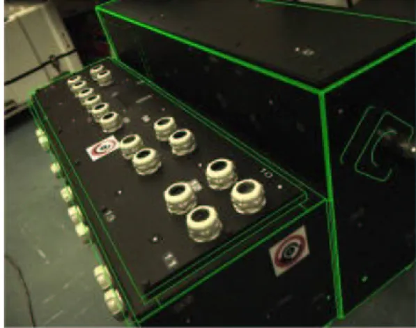
The figure 7 shows results obtained with the marker based registration. The required visual precision is achieved with a very good alignment of the 3-D model on the image. Even with a single coded marker, the pose estimation is satisfac-tory. An evaluation of the robustness of the coded marker
Figure 6. Algorithm 2 - Feature-based regis-tration.
detection showed that, for a distance of 100 cm (marker size of 50x50 pixels), the marker is always detected for an angle varying from 30o to 150o. In these conditions, the preci-sion of pose estimation from one marker is about 3mm and between 1oand 6o, depending on the viewing angles.
Con-cerning the speed performance of the algorithm, the regis-tration runs at about 30 Hz on a 3.0 GHz Pentium IV.
Figure 7. Results of the marker based regis-tration. A simplified 3-D model is displayed in wireframe representation.
We also tested the feature based registration to perform a robust tracking of a table. After a coarse initialization of the pose, performed by the marker based algorithm, the feature algorithm estimates the camera pose and projects the CAD model onto the images. We obtained similar visual quality for the second registration method.
In order to tend to a markerless augmented reality system, we are investigating on an initial step without marker rely-ing on a direct object recognition leadrely-ing to a pose estima-tion.
5. Multimedia contents
The next step is to prepare documentation for maintenance operators. The main idea is to provide easy access to tech-nical documentation as opposed to paper manuals that tend to become very cumbersome and poorly flexible as stated in [21]. By using electronic documents, we can also introduce more media, like 3D models, sounds and videos. Moreover, such electronic manuals should embed augmented reality features.
5.1. Key document: the electronic procedure
Since the maintenance procedure is the key document in such a system, all media will be related to the procedure. The choice of using an XML based technology was made to describe a typical maintenance procedure. Such choice was appropriate because a maintenance manual can be seen as a structured tree. Such a document will be composed of three main parts:
• pre-requirements: describing what operators will need
in order to start activity. It includes safety notes, tools, spares and consumables that will be required.
• available-media: naming and listing all media that may
be needed during the procedure in addition to the text of the procedure itself.
• phases: also called steps of the procedure. Such steps
are also including notes, safety recommendations and the referenced media available as an illustration of the text describing each phase.
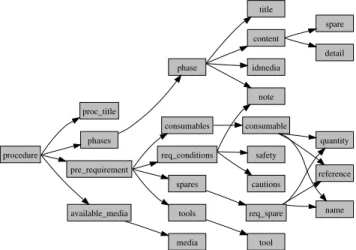
Each main part of the document and all the markup hierar-chy is displayed on figure 8. Such kind of document could be seen as a lightweight version of IETMs (which stands for Interactive Electronic Technical Manuals) that are used by the American Department of Defense [19].
As we stated, we can link each step of our key document to some media to enhance the procedure’s text understanding. These media could be: video, images (various format are accepted like jpeg, png and bmp), sounds and 3D models (registered or not with the video stream). Each kind of me-dia is handled by a specific meme-dia manager registered by the application.
In our case, 3D models are augmented with graphical assis-tance to explain the procedure’s steps. It means they meet the requirements of a special format explained below.
procedure proc_title pre_requirement available_media phases req_conditions tools spares consumables media phase safety cautions note tool req_spare consumable title content idmedia quantity reference name detail spare
Figure 8. XML markups system for mainte-nance procedures
5.2. Augmented 3D models for maintenance
The 3D models we use are the virtual counterparts or the real device we want to maintain (see figure 7). We choose to import our models using the VRML97 standard [22] since it is a widely spread standard for 3d objects that most of modelers and CAD softwares can import or export, even if it tends to be replaced by its XML successor : X3D [22]. For further development, the migration from VRML to X3D should not be a problem since X3D maintains the same scene graph and nodes. It also provides ways to add interactivity to 3D models for animating maintenance activ-ities such as disassembling. And finally, it allows to create new nodes (known as PROTOs) to fulfill our specific needs. Our models were directly exported from the ones used dur-ing the design phase of the devices to maintain. However, due to the lack of computing power of the tablet-PC we had to reduce the complexity of the CAD models. This was achieved partly automatically and partly manually until we could reach a good compromise between graphical com-plexity and rendering speed.
An other important change of the original models was to bring structure to the virtual model in order to insert assem-bly/disassembly animations.
5.2.1 From the procedure to the animations
In order to enhance our virtual model with suitable mainte-nance augmentations, we had to study several maintemainte-nance procedures and find out the commonly performed actions, and therefore synthesize these actions in our virtual model by the mean of animations.
one of the maintenance procedure we used in AMRA, con-cerning one of the maintenance operation to perform on an electrical transformer:
B1 · · ·
B2 Disconnect the electrical connections on the ’A’ side as fol-lows:
10 Remove the two self-lock nuts (14), bolts (1) and four washers (2) and disconnect the cable (13) from the LV mount on the transformer. Discard the self-lock nuts (14) and bolts (1).
20 Remove the self-lock nut (4) and the washer (5) and disconnect the cable (7) from the stud (3). Discard the self- lock nut (4).
B3 · · ·
One can see that the basic maintenance operations de-scribed by this excerpt consist in unscrewing nuts and removing the covers/cables/connectors maintained by these nuts. Therefore, we can assume that most of the unscrewing or removing actions are very similar to each other.
So, a quite simple idea was to design new VRML Nodes (also known as prototypes) whose fields and events would reflect the various features of assembly/disassembly tasks simulation such as unscrewing and removing animation, or object’s fading (for a temporary X-ray look through covers).
Moreover, these prototypes should be generic enough to act on any parts of the virtual model, so they could be used just as regular VRML grouping nodes which could contain any kind of geometry (and more generally, any kind of nodes). And finally, we should be able to link these prototypes in-stances together in order to create sequential or concurrent animations
5.2.2 New nodes design for augmenting reality
Our prototypes should provide visual simulations of main-tenance operations to the operator by animating parts of the virtual model. But animations alone are not enough, they should always be supported by a visual hint enhancing the symbolic action to be performed. For instance, unscrewing actions are enhanced by a rotating arrow, and removing is enhanced by a direction arrow. These visual hints intention-ally wears bright colors (in our case a kind of fluorescent green).
We will now focus on the development of the ”Unscrewer” prototype. As the other developed prototypes are applying the same philosophy.
This prototype is used when we have to unscrew and remove a mechanical part. Geometry of these parts are contained in the children exposedField, allowing us to unscrew any kind of shape or group of shapes. The complete architecture of
the Unscrewer proto is also shown in figure 9. Here are the different steps performed by the Unscrewer :
• The unscrewer is triggered by receiving an SFTime
event routed on the ”startTime” eventIn. Animations duration in seconds is specified by the unscrewTime
exposedField, and the removePercent field defines the
percentage of this duration dedicated to withdrawal,
• First the mechanical part is unscrewed by a number of
rounds (nbRounds field) with a specified thread (step-Size field) which allow partial or complete unscrewing. Unscrewing is enhanced by a rotating visual hint (hin-turl1 exposedField),
• Then the mechanical part is moved away at a specified
distance (removeDist field). Withdrawal is enhanced by a still direction arrow (hinturl2 exposedField),
• At the end of each step, the corresponding visual hints
appear and disappear,
• When all animations are finished the Unscrewer emits
a new SFTime event through the stopTime eventOut which could be used to start any of the developed pro-totypes in order to create linked animations,
Figure 9. Unscrewer proto architecture
5.2.3 Augmenting maintenance procedure steps
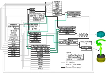
Procedures steps are instantiated in the virtual model by linking instances of the different prototypes together as ex-plained earlier. Figure 10 presents an excerpt of the Scene graph and routes graph associated to a substep of the main-tenance procedure: 6 bolt should be unscrewed before re-moving a box cover. The animation sequence is using routes between stopTime of previous nodes and startTime of next nodes:
1. First bolt is unscrewed and the material associated to all box covers (contained in ”Box Cover 1”) is faded so we could temporarily see through the box covers, 2. Then the second bolt is unscrewed,
3. And so on with the third bolt,
4. Then the three last bolts are unscrewed simultaneously, 5. And finally the box cover is moved away,
6. When withdrawal is achieved the material of the box covers is unfaded.
Group BoxCovers
Group BoxCover 1 Remover TerminalBoxCover
BoxCover 1 BoxCover Material Transform BoxCover 2 Transform Bolt BoxCoverFader 6 Anchor BoxCover 2 Starter BoxCover 2 Unscrewer Bolt 1 1 1
Bolt 1 Unscrewer Bolt 2 2
Bolt 2 Unscrewer Bolt 3
3
Bolt 3 Unscrewer Bolt 4 4 Unscrewer Bolt 5 4 Unscrewer Bolt 6 4 Bolt 4 Bolt 5 5 Bolt 6 1
Figure 10. Scene graph (plain) and route graph (dashed) of a procedure step simula-tion
5.2.4 Multimedia engine
The multimedia engine allows to bring a contextual help to each step of the procedure by using one or several avail-able media, such as photos, videos and 3D animated models which could be registered on top of the video stream com-ing from the camera.
To achieve this, such an engine had to implement several features and use several Application Programming Inter-faces (API). Our engine, written in C++, allows us to parse XML procedures using built-in XML parser of the QT li-brary, which is also able to load and display several images formats. The use of Open Inventor API was fairly indi-cated to parse and display X3D/VRML content describing
3D models. And finally, to execute javascript code intro-duced to animate 3D models, we use the NJS library, one of the former runtime cores interpreting Javascript in Netscape browsers.
More media could be taken into account, as the multimedia engine uses a plugin system allowing one media manager per type of medium. Such plugins are registered by the mul-timedia engine during application setup.
Our engine is implementing all the options needed to handle several media which could be controlled through the man machine interface detailed in the next section.
6. Man Machine Interface
6.1. Description
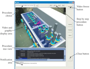
The Man Machine Interface (MMI), is organized around an area used to display both images and graphic assistance. As presented on figure 11, the virtual model could be displayed on top of the video stream.
The top of the MMI is dedicated to the maintenance proce-dure. It contains an area allowing the operator to choose the maintenance procedure to apply to the element identified by the visual registration system. The chosen procedure is dis-played below the graphic area and can be checked step by step.
Video display can be frozen which can be useful for the operator to keep a steady display allowing him to put the tablet-PC down on a table.
The notification area is used to display AMRA system infor-mation such as connections to the database or to the video server. Procedure choice Video and graphic display area Procedure tree view Notification area Video freeze button Step by step procedure button Clear button
6.2. Manipulating 3D models
Several modes of interaction with the 3D models are pro-vided to the operator. The most passive way is performed by switching from one step to another of the procedure. The 3D models will be animated when the maintenance step is requiring it. The operator can also directly interact with the 3D models by starting animations at will (registered onto video stream or not), and virtually move freely around the 3D model to see the geometry of the mechanical part he has to maintain.
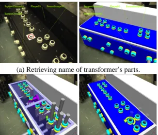
In the case of a 3D model registered on top of the video stream, we can give technical specifications of a part just by selecting it in the real image. Such a selection gives us a point on the image but also intersects the virtual model beneath, allowing us to retrieve the name and IDs of the corresponding elements in the virtual model.
A few images of the capabilities of our 3D model system are exposed in figure 12.
(a) Retrieving name of transformer’s parts.
(b) Animations illustrating a maintenance step.
Figure 12. Some 3D model manipulation ca-pabilities.
6.3. An early subjective evaluation
We proceeded to a two parts evaluation: a subjective ques-tionnaire has been developed in order to test utility and us-ability of AMRA by field operators and an expert analysis has been carried out in order to reveal usability problems. The analysis is based on [3] and is focusing on: visual ren-dering quality, comfort of use, intelligibility of the meaning of the animation, comprehension of the animations in su-perimposition with the environment, benefits of augmented reality for the application, interaction, usability of AMRA.
The answers of the overall 28 questions are marked on a scale of 7 items ranked from bad to excellent. The ques-tionnaire was ended by an interview in order to define the principal hits and negative aspects of the prototype. Even if only one operator, considered as representative of maintenance operators, participated to the evaluation, the global judgment of AMRA is positive. The results of the ergonomic expertise, showed that the two expertises con-verge on the main drawbacks of AMRA:
• The lack of spatial indications can impair the use of
AMRA in larger environments. The prototype sup-poses that the user is positioned at the right place at the right time to visualize the area of interest. If not, the user must be oriented graphically or orally toward this area,
• The end of the animations is sometimes difficult to
per-ceive. An indicator of the beginning and end of a se-quence must be provided,
• The weight of the tablet-PC, tolerable for the
evalua-tions, is too heavy for everyday use. The use of smaller devices such as pocket PC should be recommended,
• The stylus pen is not adapted to manipulation in
main-tenance environment.
The conclusions of the evaluation are positive, despite some MMI limitations that can be easily solved. AMRA is easy to handle, and its architecture related to a maintenance database can provide an interesting tool for maintenance ap-plications. The functionalities of AMRA are interesting for maintenance application, even though the technological re-alization must be more mature.
7. Conclusion
In this project, we have designed a video see-through AR system for operators training and assistance in train maintenance tasks.
An electrical transformer and its maintenance procedure provided, by the final user (ALSTOM) of the system, have been used as a test bench.
The first evaluation of this system shows that it can really be helpful for maintenance operators, as it provides, in a very intuitive manner, an easy and contextual access to technical manuals, replacing the extremely cumbersome paper documentation.
Some limitations like the weight of the hardware should be solved in a near future. Besides, we have laid the foundations for further research and development in AR system devoted to industrial applications.
Acknowledgments
This work was supported by French Ministry of Re-search (see: http://www.telecom.gouv.fr/rntl/AAP2001/-Fiches Resume/AMRA.htm). The interdisciplinary consor-tium of partners include ALSTOM (Industrial) as final user, ActiCM (startup) as a sensors integrator, CEA (Atomic En-ergy Agency) and LSC (Research Lab) as main actors of this project.
We thank all the members of our companies/labs who pro-vided helpful insights for this project : engineers (especially Fabien Dory) as well as maintenance operators. And fi-nally, we would like to “special thank” Christine M´egard who supported this project all the way through.
References
[1] A. Ansar and K. Daniilidis. Linear pose estimation from points or lines. IEEE Transactions on Pattern Analysis and
Machine Intelligence, 25(5):578–589, 2003.
[2] Arvika. Arvika, augmented reality for development, pro-duction and servicing. Available at ”http://www.arvika.de”, 1999.
[3] C. Bach and D. Scapin. Recommendations ergonomiques pour l’inspection d’environnements virtuels. EUREKA-COMEDIA project report. Technical report, INRIA Roc-quencourt, France., 2003.
[4] G. Baratoff, A. Neubeck, and H. Regenbrecht. Interactive multi-marker calibration for augmented reality applications. In Proceedings of 2002 IEEE / ACM International
Sympo-sium on Mixed and Augmented Reality (ISMAR 2002), pages
107–116, 2002.
[5] M. Billinghurst and H. Kato. Collaborative augmented real-ity. Communications of the ACM, 45(7):64–70, 2002. [6] J. Bruce, T. Balch, and M. Veloso. Fast and inexpensive
color image segmentation for interactive robots. In
Proceed-ings of the 2000 IEEE/RSJ International Conference on In-telligent Robots and Systems (IROS ’00), volume 3, pages
2061 – 2066, October 2000.
[7] T. Caudell and D. Mizell. Augmented reality: an applica-tion of heads-up display technology to manual manufactur-ing processes. In Proceedmanufactur-ings of the Twenty-Fifth Hawaii
In-ternational Conference on System Sciences, volume 2, pages
659–669, January, 7-10 1992.
[8] F. Chang, C. Chen, and C. Lu. A linear-time component-labeling algorithm using contour tracing technique.
Com-puter Vision and Image Understanding, 93(2):206–220,
Februrary 2004.
[9] D. F. Dementhon and L. S. Davis. Model-based object pose in 25 lines of code. Int. J. Comput. Vision, 15(1-2):123–141, 1995.
[10] T. Drummond and R. Cipolla. Real-time visual tracking of complex structures. IEEE Transactions on Pattern Analysis
and Machine Intelligence, 15(1):932–946, July 2002.
[11] S. Feiner, B. MacIntyre, and D. Seligmann. Knowledge-based augmented reality. Commun. ACM, 36(7):52–62, July 1993.
[12] M. A. Fischler and R. C. Bolles. Random sample consen-sus: a paradigm for model fitting with applications to im-age analysis and automated cartography. Commun. ACM, 24(6):381–395, 1981.
[13] F. Gaspard, S. Naudet, E. Noirfalise, and P. Sayd. Cibles cod´ees et proc´ed´e de photogramm´etrie utilisant de telles cibles. Patent, (PCT/fr/03/50101), 2002.
[14] G. Klinker, O. Creighton, A. H. Dutoit, R. Kobylinski, C. Vilsmeier, and B. Brugge. Augmented maintenance of powerplants: a prototyping case study of a mobile ar system. In IEEE and ACM International Symposium on Augmented
Reality (ISAR’01), pages 124–133, New York, October,
29-30 2001.
[15] E. Marchand, P. Bouthemy, F. Chaumette, and V. Moreau. Robust real-time visual tracking using a 2d-3d model-based approach. In IEEE International Conference on Computer
Vision (ICCV), volume 1, pages 262–268. IEEE, September
1999.
[16] D. Reiners, D. Stricker, G. Klinker, and S. Muller. Aug-mented reality for contruction task: Doorlock assembly. In
Proceedings 1st International Workshop on Augmented Re-ality (IWAR’98), pages 31–46, 1998.
[17] J. Rekimoto and Y. Ayatsuka. Cybercode: designing aug-mented reality environments with visual tags. In DARE ’00:
Proceedings of DARE 2000 on Designing augmented reality environments, pages 1–10. ACM Press, 2000.
[18] B. Schwald and B. de Laval. An augmented reality system for training and assistence to maintenance in the industrial context. In Proc. 11th International Conference in Central
Europe on Computer Graphics, Visualization and Computer Vision’2003 (WSCG), 2003.
[19] US Navy. IETM. Interactive Electronic Technical Manuals., 2000. available at ”www.ietm.net”.
[20] L. Vacchetti, V. Lepetit, and P. Fua. Stable real-time 3d tracking using online and offline information. IEEE Trans.
Pattern Analysis and Machine Intelligence, 26(10):1385–
1391, 2004.
[21] C. Ventura. Why switch from paper to electronic manuals. In DOCPROCS ’88: Proceedings of the ACM Conference
on Document Processing Systems, pages 111–116, 1988.
[22] Web3D Consortium. X3D and Related Specifications. avail-able at ”www.web3d.org/x3d/specifications/”.
[23] A. Webster, S. Feiner, B. MacIntyre, W. Massie, and T. Kruger. Augmented reality in architectural construction,
inspection, and renovation. In Proceedings of the Third
ASCE Congress for Computing in Civil Engineering, pages
913–919, Anaheim, June 1996.
[24] X. Zhang, S. Fronz, and N. Navab. Visual marker detec-tion and decoding in ar systems: A comparative study. In
Proceedings of 2002 IEEE / ACM International Symposium on Mixed and Augmented Reality (ISMAR 2002), pages 97–