PFC/RR-96-1
Decomposition of Chlorinated Ethylenes and Ethanes in an Electron Beam
Generated Plasma Reactor Steven A. Vitale
S.M. Thesis Plasma Fusion Center
Massachusetts Institute of Technology Cambridge, Massachusetts 02139
February, 1996
This work supported by the Contaminant Plume Containment and Remediation Focus Area, Office of Environmental Management, U.S. Department of Energy.
Decomposition of Chlorinated Ethylenes
and Ethanes in an Electron Beam
Generated Plasma Reactor
by
Steven A. Vitale
Submitted to the Department of Nuclear Engineering in Partial Fulfillment of the Requirements for the
Degree of
Master of Science
in Nuclear Engineering
at the
Massachusetts Institute of Technology
February 1996@ 1996 Steven A. Vitale All rights reserved
The author hereby grants to MIT permission to reproduce and to distribute publicly paper and electronic copies of this thesis document in whole or in part.
Signature of Author -Steven A. Vitale Certified by Dr. Daniel R. Cohn, Ph.D. thesis supervisor Certified by Pth Je frey Freidberg thesis reader Certified by Prof. f y F idberg
Decomposition of Chlorinated Ethylenes
and Ethanes in an Electron Beam
Generated Plasma Reactor
by
Steven A. Vitale
Abstract
An electron beam generated plasma reactor (EBGPR) is used to determine the plasma chemistry kinetics. energetics and decomposition pathways of six chlorinated ethylenes and ethanes: 1 .1 .1 -trichloroethane, 1,1 -dichloroethane. ethyl chloride.
trichloroethylene, 1,1 -dichloroethylene. and vinyl chloride. A traditional chemical kinetic and chemical engineering analysis of the data from the EBGPR is performed, and the following hypothesis was verified:
The specific energy required for chlorinated VOC decomposition in the electron beam generated plasma reactor is determined by the electron attachment coefficient of the
VOC and the susceptibility of the molecule to radical attack.
Of the chlorinated ethanes, 1.1,1-trichloroethane is shown to decompose with the least energy, followed by 1.1 -dichloroethane and ethyl chloride. Of the chlorinated ethylenes, trichloroethylene decomposes using the least energy, followed by
dichloroethylene and vinyl chloride. This pattern follows the known electron attachment coefficients of these compounds; molecules with higher dissociative electron attachment coefficients are shown quantitatively to decompose more readily than those with lower attachment rates.
Comparing compounds with the same number of chlorines, e.g.,
1,1,1-trichloroethane and trichloroethylene. it is seen that the chlorinated ethylene decomposes more readily than the chlorinated ethane. This is shown to be true for all three
ethane/ethylene pairs. Chlorinated ethylenes are more susceptible to radical attack than ethanes, thus the decomposition of the ethylenes is enhanced by radical reactions, and less energy is required for decomposition.
Several theoretical treatments are provided to aid in analyzing the data. A radiation chemistry approach was used to derive an expression to relate the VOC concentration to the electron beam dose through the G-value of the molecule, or
equivalently, the beta value. A differential kinetic approach is used to determine the order with respect to time nt and the order with respect to concentration. nc. for each of the six chlorinated VOCs. The reaction rate constants for the decomposition reaction are also determined. An integral kinetic model. the INHIBIT model, is derived analytically from a
simplified set of chemical reactions to account for some of the apparent inhibition of the reaction by products.
A traditional chemical engineering analysis is applied to the EBGPR by modeling it as an ideal plug flow reactor. This allows the derivation a modified performance
equation relating the VOC outlet concentration from the reactor to the reactor power required, through the reaction rate expression
Nearly 4000 data points were collected with the EBGPR over the 15 month period of this study. These data points are used in conjunction with the differential and integral
kinetic models described above to determine several quantities of interest for each of the six VOCs in this study. The rate constants, k, and unimolecular reaction orders, nt, were determined. Best fits to the INHIBIT model gave values of two fitting parameters, K and P', to allow a calculated analytic expression of the VOC concentration as a function of electron beam dose. The parameter K gives an indication of the importance of inhibition in the reaction mechanism: if K is near zero, then inhibition is unimportant, and the reaction follows first order exponential decay behavior. If K is non-zero, than the reaction appears to have inhibited kinetics, and the reaction follows a non-linear decay pattern.
Measurements are given of all of the identifiable reaction product abundances. This information was used in conjunction with the kinetic analysis to determine possible
reaction pathways for decomposition in the reactor. Reaction pathways for all six chlorinated ethylenes and ethanes were proposed. The mast important major reaction products in every case were carbon dioxide, carbon monoxide, and hydrogen chloride. Many other minor decomposition products were also observed.
Rosocha
D-values
and specific energies, E, were determined for each VOC as a function of concentration. Unlike the efforts of previous research groups, in this study, 0 and e are allowed to be functions of concentration. For most compounds, the two values do in fact have a marked dependence on inlet concentration. For cases where previous literature values forP
are available at a known concentration, the results agree very well with those from the EBGPR. This result is important to both the EBGPR study and the previous works, because it provides verification of the results of both studies. It also serves to show that the dosimetry calculation performed on the EBGPR have given reasonable values, since theP-values
obtained are directly related to the knowledge of the electron beam dose.Thesis Supervisor: Dr. Daniel R. Cohn
Head of the Plasma Technology and Systems Division, MIT Plasma Fusion Center
Table of Contents
T itle P a g e ... 1 A b stract... ... List of Figures... 7 List of Tables... 9 1. Introduction... 10 1.1 Background... 101 .2 Electron Beam Generated Plasma Reactor... 10
1.3 Review of Plasma Processing of Chlorinated Compounds ... 12
1.4 Objective ... 15
1.4.1 Hypothesis... 15
1.4.2 M ethod for Verification of Hypothesis... 16
1.5 Overview... 19
1.5.1 Organization of the Present W ork... 19
1.5.2 Contribution of the Present W ork... 19
2. Chemistry in the Reactor... 21
2.1 Radiation Chemistry... 21
2.2 Chemical Kinetics... 25
2.2.1 Idealized Chemical Reactors... 26
2.2.2 Modification of the Performance Equation for the EBGPR.... 33
2.2.3 Inhibitor Model and Integral Analysis... 35
2.2.3 Differential Analysis... 40
2.3 Summary... 45
3. Experimental M ethods... 47
3.1 Gas M ixing System ... 47
3.2 Electron Beam Generated Plasma Reactor... 47
3.3 Reaction Cham ber Design... 48
3.3.1 Temperature Studies in the Cylindrical Reaction Chamber... 51
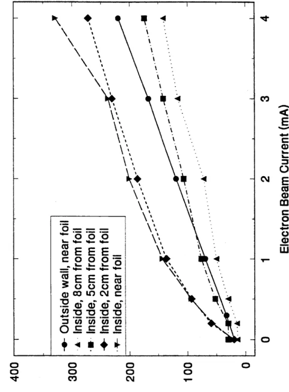
3.3.2 Dosimetry in the Cylindrical Reaction Chamber...54
3.4 Gas Analysis System ... .. ... ... 57
4. Experimental Results and Discussion... 60
4.1 General Remarks... ... 60
4.2 General Plasm a Chem istry ... 60
4.2.1 Plasm a Chem istry of Ethanes and Ethylenes ... 64
4.3 1.1.1-Trichloroethane... 66 4.4 Trichloroethylene... ... 84 4.5 1.1-Dichloroethane... 98 4.6 Dichloroethylene... 107 4.7 Ethyl Chloride... 123 4.8 Vinyl Chloride... ... 134
4.9 Other Chem icals... 150
5. Discussion of Hy pothesis... 161
6.1 Suggestions for Future Study... 173
7. References... 175
Appendix A: Derivation of INHIBIT Model Equation... 184
Appendix B: Derivation of Dose Equation... 186
List of Figures
1.1 Chemical structure of chlorinated ethylenes and ethanes 2.1 Ideal chemical reactors
2.2 Illustration of differential kinetic method. order with respect to concentration 3.1 Rectangular reaction chamber diagram
3.2 Cylindrical reaction chamber diagram
3.3 Temperature profile in the cylindrical reaction chamber
3.4 Temperature profile in the cylindrical reaction chamber with auxiliary air cooling 3.5a Energy deposition profiles in the rectangular reaction chamber
3.5b Energy deposition profiles in the cylindrical reaction chamber 4.1 TCA concentration versus electron beam dose
4.2 nc graph for TCA 4.3 nt graph for TCA
4.4a Pseudobeta versus TCA inlet concentration
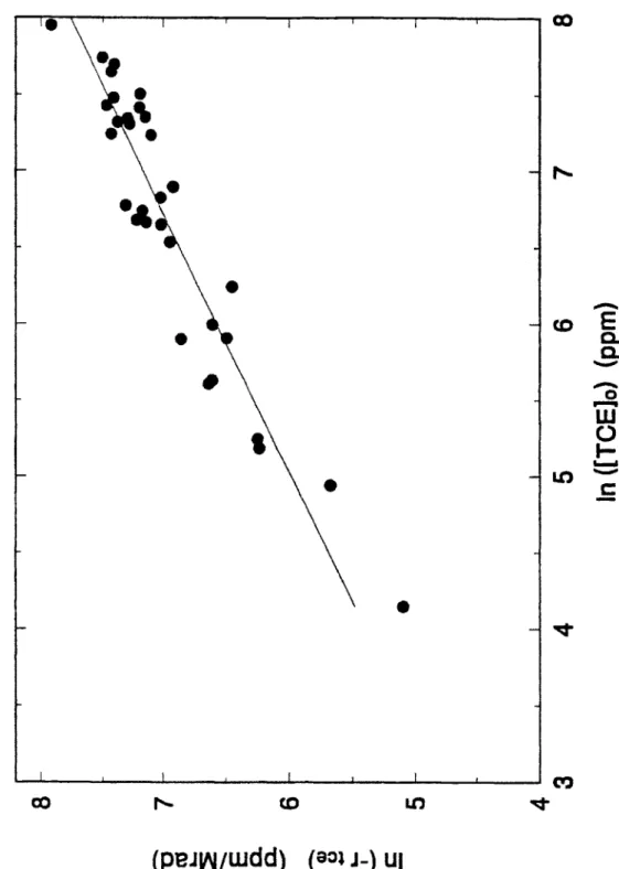
4.4b Calculated TCA results from INHIBIT model fit with pseudobeta parameters 4.5 Rosocha
P(
values for TCA as a function of inlet concentration4.6 Major TCA decomposition products as a function of electron beam dose 4.7 Minor TCA decomposition products as a function of electron beam dose 4.8. Energy expense for TCA decomposition as a function of inlet concentration 4.9 Schematic of TCA decomposition pathways
4.10 TCE concentration versus electron beam dose 4.11 nc graph for TCE
4.12 nt graph for TCE
4.1 3a Pseudobeta versus TCE inlet concentration
4.1 3b Calculated TCE results from INHIBIT model fit with pseudobeta parameters 4.14 Rosocha
P
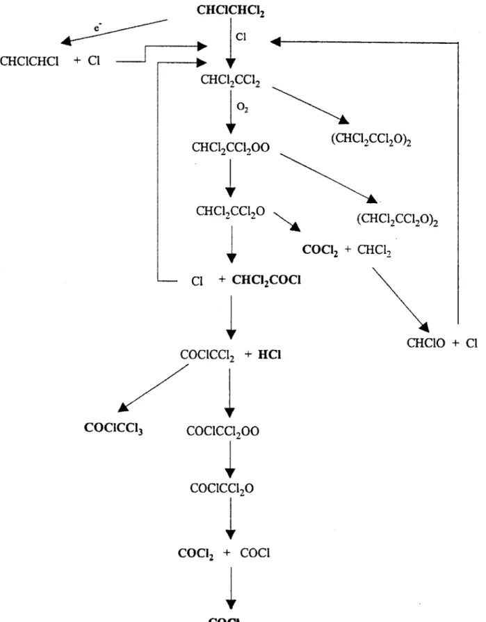
values for TCE as a function of inlet concentration4.1Sa Major TCE decomposition products as a function of electron beam dose 4.15b Minor TCE decomposition products as a function of electron beam dose 4.16 Energy expense for TCE decomposition as a function of inlet concentration 4.17 Schematic of TCE decomposition pathways
4.18 DCA concentration versus electron beam dose 4.19 nc graph for DCA
4.20 n, graph for DCA
4.21 a Pseudobeta versus DCA inlet concentration
4.2 1b Calculated DCA results from INHIBIT model fit with pseudobeta parameters 4.22 Rosocha
(
values for DCA as a function of inlet concentration4.23a Major DCA decomposition products as a function of electron beam dose 4.24 Energy expense for DCA decomposition as a function of inlet concentration 4.25 Schematic of DCA decomposition pathways
4.26 DCE concentration versus electron beam dose 4.27 nc graph for DCE
4.28 nt graph for DCE
4.29b Calculated DCE results from INHIBIT model fit with pseudobeta parameters 4.30 Rosocha
P
values for DCE as a function of inlet concentration4.31 a Major DCE decomposition products as a function of electron beam dose 4.32 Energy expense for DCE decomposition as a function of inlet concentration 4.33 Schematic of DCE decomposition pathways
4.34 EC concentration versus electron beam dose 4.35 n, graph for EC
4.36 nt graph for EC
4.37a Pseudobeta versus EC inlet concentration
4.37b Calculated EC results from INHIBIT model fit with pseudobeta parameters 4.38 Rosocha
P
values for EC as a function of inlet concentration4.39a Major EC decomposition products as a function of electron beam dose 4.40 Energy expense for EC decomposition as a function of inlet concentration 4.41 Schematic of EC decomposition pathways
4.42 VC concentration versus electron beam dose 4.43 nc graph for VC
4.44 nt graph for VC
4.45a Pseudobeta versus VC inlet concentration
4.45b Calculated VC results from INHIBIT model fit with pseudobeta parameters 4.46 Rosocha
P
values for VC as a function of inlet concentration4.47a Major VC decomposition products as a function of electron beam dose 4.48 Energy expense for VC decomposition as a function of inlet concentration 4.49 Schematic of VC decomposition pathways
4.50 CC14 concentration versus electron beam dose
4.51 Rosocha
P
values for CCI4 as a function of inlet concentration4.52 1,1,2-TCA concentration versus electron beam dose
4.53 Rosocha
P
values for 1,1,2-TCA as a function of inlet concentration 4.54 PCE concentration versus electron beam dose4.55 Rosocha
P
values for PCE as a function of inlet concentration 4.56 Freon I 13 concentration versus electron beam dose4.57 Rosocha
P
values for Freon 113 as a function of inlet concentration 4.58 Toluene concentration versus electron beam dose4.59 Rosocha
P
values for Toluene as a function of inlet concentration5.1 Energy expense for decomposition of chlorinated ethanes
5.2 Energy expense for decomposition of chlorinated ethylenes
5.3 Comparison of TCA and TCA decomposition 5.4 Comparison of DCA and DCE decomposition
List of Tables
1.1 Available literature on plasma processing of chlorinated VOCs 2.1 Summary of integral models for VOC decomposition
2.2 Summary of energy expense models for VOC decomposition 3.1 Monte Carlo results for electron beam dosimetry calculations
5.1 Electron attachment coefficients
1. Introduction
1.1. Background
The electron beam generated plasma reactor (EBGPR) project began at MIT in 1990 to evaluate the utility of using non-equilibrium electron beam generated plasmas for the decomposition of chlorinated VOCs present at government hazardous waste sties. At these hazardous waste sites, tons of chlorinated solvents were to be vapor extracted from the soil, and the resultant VOC-laden air stream would be passed through the EBGPR for treatment. This process was put into practice in January, 1995, when a field scale
demonstration unit of the EBGPR was used at Hanford, Washington to decompose carbon tetrachloride (CCI4) in a soil vapor extracted air stream.
Extensive laboratory study of the decomposition of CCl4 preceded the field test.
A comprehensive review of the design of the laboratory version of the EBGPR and of carbon tetrachloride decomposition can be found in the thesis of Mathias Koch') and in several papers 24). Any references to Koch in this work will be to the thesis. unless otherwise stated. After the successful completion of the CC14 analysis. it was determined
that the EBGPR could be used as a very versatile instrument for the study of the plasma chemistry kinetics of decomposition of many types of compounds. Other research groups have studied the energetics of decomposition of compounds such as trichloroethane and trichloroethylene. but these studies were conducted over limited concentration ranges, and they have concentrated on the determination of the specific energy, F. required for decomposition of the chlorinated compounds. The specific energy was assumed to be independent of inlet concentration and other parameters, and little work has been done to attempt to explain the results of chlorinated ethane or ethylene decomposition
quantitatively. The present work will explore quantitatively and qualitatively the plasma chemistry and energetics of chlorinated ethane and ethylene decomposition in the EBGPR.
1.2 The Electron Beam Generated Plasma Reactor
The energy efficient nature of the EBGPR as compared to thermal plasma or thermal oxidation methods has been discussed elsewhere(23-. A very brief summary of this argument is that the energy from the electron beam is directed preferentially towards the decomposition of the chlorinated organics in an air stream, due to their high
dissociative electron attachment cross-section. This results in little energy being transferred to the carrier gas molecules and ions, and thus not much energy is wasted in
vibrational and rotational mode heating of the carrier gas.
A previously unexamined feature of the EBGPR is that its ease of operation makes it well suited to the examination of the plasma chemistry and radiation chemistry
of many different compounds. In this work, the term plasma chemistry will refer to the kinetics and reaction pathways of the reactions in the plasma, and the term radiation chemistry or energetics will refer to the energy requirements for decomposition of the molecules under irradiation by electrons in the EBGPR specifically. The EBGPR has several advantages over other types of plasma processes for these studies. which will be discussed in detail below:
* Atmospheric pressure operation " Easily controlled radiation dose * Widely variable flow rate * Steady state operation
* Plasma can be created in nearly any type of carrier gas
* Additives or contaminants will not quench or inhibit plasma formation * Reaction products such as particulates will not damage system
Most industrially relevant processes would be run optimally at atmospheric pressure to allow maximum fiowrates and to reduce capital costs. Therefore the study of plasma and radiation chemistry at atmospheric pressure is essential for accurate modeling of the process for scale up to industrial size reactors. Other types of plasmas. e.g. corona discharges and microwave cavity experiments, can operate only with relatively small plasma volumes at atmospheric pressure. This results in a heterogeneous reactor volume on a macroscopic scale. and thus makes it difficult to perform accurate analyses of the
plasma chemistry. Electron beam generated plasmas do not have this difficulty, however, since energetic electrons have a relatively large penetration distance in air. In the
laboratory reactor, the penetration depth of the electrons in air is approximately 5 cm; the field unit has a penetration depth of approximately twice that.
The electron beam dose to the plasma in radiation and plasma chemistry is the analog to residence time in the reactor for traditional chemical kinetics. In order to perform steady state kinetic studies, traditionally one must be able to vary the residence time in the reactor over a wide range. This is usually done by varying the flowrate of the reactants through a traditional chemical reactor. In plasma chemistry studies. the effective residence time is the energy dose, which may be varied through either the reactant
flowTate or the power coupled to the plasma. However, in corona discharges and microwave plasmas. these parameters are not independently variable. Breakdown in a
microwave plasma will only occur if the power coupled to the plasma exceeds some threshold value. Thus studies at low energy densities cannot be easily conducted. In corona reactors. the power discharged to the plasma is often fixed by capacitors and is not easily varied. The EBGPR. does not have any of these drawbacks, since a plasma may be produced at any flowrate. and the power coupled to the plasma is easily controlled from
zero up to the maximum power of the reactor through control of the electron beam current.
Kinetic studies of gas phase reactions are typically easier to perform in a steady state reactor rather than in batch operations, if the nature of the chemical species allow it.
to change a flovTate and sample the exit stream in a steady state process than to clean, recharge, wait. and sample a batch reactor. Steady state operation also helps to insure the homogeneity and reproducibility of the process.
Electron beam generated plasmas can be created in any type of carrier gas. The energetic electrons from the beam possess enough energy to ionize any species, and charge transfer processes will result in the transfer of this energy to the chlorinated molecules in the stream. This is discussed more thoroughly in Section 4.2. Although all of the experiments in this work were conducted using air as the carrier gas, further reaction pathway and kinetic studies would benefit from studies of the VOC reactions in pure nitrogen. pure oxygen, pure hydrogen, and other gases. Energy requirements for
breakdown in microwave and corona plasmas are dependent upon the nature of the carrier gas, however plasmas of any desired energy density can be created in the EBGPR
independently of the carrier gas used. Similarly, other reactants such as hydrogen peroxide or water can be added to catalyze or inhibit the reactions without any adverse affects on the plasma. Reaction byproducts such as particulates or corrosive radicals will not cause quenching of the plasma. or significantly change its characteristics.
Thus the EBGPR has great value as a tool with which to study plasma chemistry effects of many compounds under a wide variety of experimental conditions. Specifically, this work will examine the reaction pathways, kinetics, and energetics of chlorinated ethane and ethylene decomposition.
This study of the plasma chemistry of chlorinated ethylenes and ethanes will aid in the understanding of halogenated VOC decomposition in the EBGPR. This will allow the design of more efficient reactors for both commercial and remediation use.
Furthermore, this study will allow a better understanding of the limitations of the EBGPR in processing of certain types of compounds. as well as the advantages that the EBGPR has over conventional and other emerging technologies. The work of Koch has established the viability of the EBGPR for carbon tetrachloride decomposition, and the Hanford. Washington field test showed that the reactor could perform reliably under "real-world" conditions. This study will build upon the previous work, by showing that the energy efficient reactor is capable of decomposing a variety of chlorinated
compounds, and as such it can be a valuable tool as a commercial unit operation in the chemical process industry and at many remediation sites.
1.3 Review of Plasma Processing of Chlorinated Compounds
Plasma processing of chemicals is an expanding field, and many research groups around the world are currently investigating innovative approaches. A brief listing of some of these research efforts is given it table 1.1 to put the current work into
perspective. Note that the listing is limited only to publications which include chlorinated methanes, ethanes. or ethylenes: and even in that limited scope it is not comprehensive. This list does not include the extensive work performed on the plasma processing of NOR,
SOX, methane, acetylene, ammonia, fluorinated compounds, or plasma chemical synthesis methods.
Chemicals of Interest Type of Plasma Reference VC Electron Beam 5 TCE Microwave 6 Corona Discharge 7 Dielectric Barrier 8 Dielectric Barrier 9 Dielectric Barrier 10 Dielectric Barrier 11 Dielectric Barrier 12
CC4, TCE Electron Beam 13
TCE Electron Beam 14
CHF2CI. C2C13F3 Dielectric Barrier 15
Corona Discharge 16
Corona Discharge 17
Corona Discharge and Ferroelectric Packed 18 Bed
Corona Discharge 19
VC Electron Beam 20
VC Pulse Ionization Chamber 21
TCE Dielectric Barrier and Pulsed Corona 22
TCE Electron Beam 23
TCE Electron Beam 24
Pulsed Corona and Ferroelectric Packed 25 Bed Dielectric Barrier 26 Dielectric Barrier 27 Dielectric Barrier 28 Dielectric Barrier 29 Dielectric Barrier 30 Dielectric Barrier 31 Dielectric Barrier 32 Surface Discharge 33 Surface Discharge 34 Gliding Arc 35 Gliding Arc 36 Microwave 37
CCI4 Electron Beam and Pulsed Corona 38
CH2Cl, Pulsed Corona 39
CCI4. TCE. CH-,Cl1 Electron Beam and Pulsed Corona 40
CHFC-). CHF2Cl. TCA. TCE. C2C14 Microwave 41
CHCI3, TCE. C6H.Cl Microwave 43
TCE, C2Cl4 Dielectric Barrier 44
CC14 Pulsed Microwave 45
CCl2F2 DC Arc 46
CHCl3, CC 4, CH3CI Dielectric Barrier 47
CH3CI,CH-Cl, CHCI3. CC14 r.f. Discharge 48
CCI2F2, CCIF3 Dielectric Barrier 49
C6C16 Dielectric Barrier 50
C6H5Cl Glow Discharge 51
C6C16 Dielectric Barrier 52
C6C16 Dielectric Barrier 53
MeSiCI3 Dielectric Barrier 54
MeSiCl3 Dielectric Barrier 55
C6H5CI Glow Discharge 56
C6H5CI Corona Discharge 57
Me-,Cl 2Si Dielectric Barrier 58
C6H5Cl Glow Discharge 59
CCI4 Dielectric Barrier 60
SiC14 Glow Discharge 61
CCl4 r.f. Glow Discharge 62
chlorobenzenes r.f. Glow Discharge 63
chlorobenzenes r.f. Glow Discharge 64
VC Dielectric Barrier 65
chlorinated hydrocarbons Plasma Jet 66
CC 4 r.f. Discharge 67
r.f. Discharge 68
C2C14, C2C1402 r.f. Discharge 69
TCA, TCE, CC!4 Dielectric Barrier 70
1,2-DCA, TCE Plasmatron 71
TCE Corona Discharge 72
1.2-DCA Capacitively Coupled r.f. 73
Table 1.1: TCA=1.1.1-trichloroethane, DCA=1,1-dichloroethane. EC=ethyl chloride, TCE=trichloroethylene, DCE=1,1-dichloroethylene, and VC=vinyl chloride. Available
literature references on chlorinated VOC processing in plasma reactors. Where a chemical compound is not given in the table, the reference was not available to the author at the
1.4 Objectives
The objective of this study will be to perform an analysis of the decomposition pathways, the kinetics, and the energetics of the reactions of six chlorinated compounds:
1.1,1-trichloroethane (TCA). 1,1-dichloroethane (DCA). ethyl chloride (EC), trichloroethylene (TCE). 1,1 -dichloroethylene (DCE), and vinyl chloride (VC). The analysis of these compounds will be used in conjunction with the known physical and chemical properties of these compounds to attempt to formulate a basis for understanding the trends observed in the energy requirements for decomposition in the reactor. It is believed that a relationship exists between the energy required for the decomposition of a particular molecule and the chemical structure that molecule. and that this relationship can be characterized by a study of specific series of chemicals. This idea is put in the form of a hypothesis in the following subsection.
1.4.1 Hypothesis of Chlorinated Compound Decomposition in the EBGPR
One major objective of this study will be to relate the specific energy required for decomposition of the molecules to the plasma chemistry of those molecules in the reactor. By analyzing the reaction kinetics, this study will seek to verify or disprove the following hypothesis:
The specific energy required for chlorinated VOC decomposition in the electron beam generated plasma reactor is determined by the electron attachment coefficient of the
VOC and the susceptibility of the molecule to radical attack
Knowledge of these two factors for a particular compound will allow reasonable predictions of the specific energy required for the decomposition of a molecule in the EBGPR.
The electron attachment coefficient of a molecule is a measure of the affinity of the molecule for the capture of a free electron. This, in turn, is primarily determined by the individual atoms which compose the molecule; bond order and group functionality is only of secondary importance. For halogenated molecules the electron attachment coefficient is determined primarily by the number of halogen atoms on the molecule, since halogen atoms have a very high electron affinity compared to carbon, oxygen, or nitrogen. In the case of chlorinated molecules, which are the focus of this study, molecules which possess more chlorines per carbon will have a higher electron attachment coefficient. Assuming that dissociative electron attachment is the primary decomposition mechanism in the reactor, the higher the electron attachment coefficient, the more easily a molecule is decomposed in the reactor. Thus a molecule such as trichloroethane (which has 3 chlorines) will require less energy for decomposition than dichloroethane (which 2 chlorines). The quantitative verification that the specific energy
required for decomposition is related directly to the electron affinity of the molecule is the first requirement to verify the above stated hypothesis.
Trichloroethylene and 1.1.1 -trichloroethane both have three chlorine atoms per molecule, and thus using the above argument both molecules should decompose with similar specific energy requirements. However, it will been shown in Chapter 5 that trichloroethane requires 15 to 75 times more energy for decomposition than
trichloroethylene. Thus a second factor is also needed to account for the energetics of VOC decomposition. This factor is the susceptibility of a molecule to radical attack, as explained below.
The decomposition pathways of a molecule and its susceptibility to radical attack are determined by the chemical structure of the molecule. For example. simple
chlorinated methanes such as carbon tetrachloride have only a limited number of possible decomposition pathways available. Carbon tetrachloride is not very susceptible to oxygen radical attack, and chlorine radical attack will at most result in chlorine-chlorine
substitution. Thus CC14 is difficult to decompose compared to chloroform (CHCl3) which
is susceptible to both kinds of radical attack, as well as hydrogen atom abstraction. Chlorinated ethanes are more complicated molecules, and thus have more possible
decomposition pathways. Chlorinated ethylenes possess a carbon-carbon double bond and have decomposition pathways available to them which are forbidden to chlorinated
ethanes or methanes. In order to understand how the pathways of VOC decomposition affects the energy required for decomposition, one must first know what those pathways are. The elucidation of decomposition mechanisms for chlorinated ethanes and ethylenes is within the scope of this work, and detailed pathways are proposed in Chapter 4. Note that full reaction mechanism studies are complicated, and require many experiments under different reaction conditions to determine specific mechanisms. This is beyond the scope of the present work. and only reasonable reaction pathways are proposed in
Chapter 4 to account for the formation of product species and the observed reaction kinetics. Reaction pathways have been proposed previously in which trichloroethylene decomposes by a chlorine radical addition chain reaction mechanism which is not available to trichloroethane. This chain reaction mechanism results in the decomposition of a large number of molecules from a single electron attachment event. and may explain the result that trichloroethylene decomposes much more easily than trichloroethane. Similar results are expected for other chlorinated ethylenes and ethanes which have not previously been studied. The quantitative verification that the carbon-carbon double bond and other chemical properties of these molecules influence the susceptibility of the
molecule to radical attack, and by consequence, the specific energy required for decomposition, is the second requirement to verify the above stated hypothesis.
1.4.2 Method for Verification of Hypothesis
By studying the decomposition of six molecules in the reactor. it is believed that a quantitative analysis of the above hypothesis can be performed. Three chlorinated ethanes will be studied: 1.1,1-trichloroethane (TCA), 1,1-dichloroethane (DCA), and
molecules is shown in figure 1.1. Although not obvious from the brief summary above, the decomposition mechanisms of these molecules is believed to be quite similar under the conditions in this study. By studying this series of chlorinated ethanes, the second factor influencing specific energy requirements for decomposition, i.e., the susceptibility to radical attack, can be held "constant" while the first variable. i.e., the number of chlorines on the molecule. is varied. In addition, three chlorinated ethylenes will also be studied: trichloroethylene (TCE), dichloroethylene (DCE), and monochloroethylene (commonly called vinyl chloride, VC). The chemical structure of these molecules is also shown in figure 1.1. The same analysis can be performed on this series of chlorinated ethylenes: the second variable can be held "constant" while the first variable is varied. Looking at these two series of molecules will allow the study of the specific energy required for decomposition as a function of electron affinity.
The decomposition mechanisms of chlorinated ethylenes are very different from chlorinated ethanes. as described briefly in the TCA/TCE example above. By comparing the specific energy for decomposition of TCA and TCE. the electron affinity of the molecules can be held -constant" (since they each possess three chlorines) and the effect of the different reaction mechanisms can be studied. The same is true for DCA and DCE, as well as for EC and VC. Through the study of the decomposition of these three pairs, a quantitative analysis of the effect of the susceptibility to radical attack on the energetics of VOC decomposition in the reactor can be performed.
CI\
H
Cl-C-C
-H
Cl
H
1,1,1 -Trichloroethane (TCA)Cl\
H
Cl-C-C-H
H
H
1,1-Dichloroethane (DCA)
Cl\
H
H -C-CH
H
H4
Ethyl Chloride (EC)
Cl\
H
C=C
Cl
Cl
Trichloroethylene (TCE)
Cl\
H
C=C
Cl
H
1,1-Dichloroethylene (DCE)
Cl\
H
C=C
H
H
Vinyl Chloride (VC)
1.5 Overview
1.5.1 Organization of the Present Work
This thesis is organized into seven sections: an Introduction, a chapter on Reactor Chemistry, a chapter on Experimental Procedures, a chapter giving the Results and Discussion. and chapters on the Discussion of the Hypothesis, a Conclusion. and Appendices.
The Introduction serves to: explain the background of the project. provide a listing of available literature references, state clearly the objectives of the project, and emphasize the contribution of this work compared to previous studies.
The Reactor Chemistry chapter summarizes some of the important aspects of the field required to understand the results and discussion. Derivation of the electron beam dose, G-value, and P-values are given. Chemical kinetics are described by both an
inhibitor model and a differential method, which allow complementary treatments of the data.
The Experimental Procedures chapter briefly describes the EBGPR. the inlet gas system, and the gas analysis system. The redesign of the reaction chamber is also
described. as well as the results of new dosimetry calculations in this reaction chamber. The Results and Discussion chapter is divided into eight sections: a brief
overview, one section for each of the chlorinated ethylenes and ethanes compound studied, plus a final section for the results from miscellaneous other compounds. This section will extract the
p-values
and kinetic constants from the data. Reaction pathways for decomposition will also be proposed.The Discussion of the Hypothesis chapter will summarize the data from the previous chapter into a unified discussion relating the specific energy requirements for decomposition to the electron attachment coefficients and decomposition mechanisms of the molecules.
The Conclusion will summarize all of the results and suggest future areas for research. The Appendices will give the derivations of some of the equations.
1.5.2 Contribution of the Present Work
As discussed in Section 1.3. a large amount of literature information is available on the decomposition of VOC's in plasma reactors. The present work contributes to this
decomposition in an electron beam generated plasma reactor. The following aspects of this project are. to the author's knowledge, unexplored in the available literature: 1. While detailed analysis of TCA. TCE, and VC decomposition in plasma reactors has been performed previously, such analyses for DCA, DCE. and EC are not available. In this work. reaction pathways and energetic analysis of all of these compounds are proposed.
2. Traditional kinetic analyses are performed on the data, to extract reaction rate constants, reaction orders, and to provide insight into inhibition of the reactions by decomposition products.
3. Previous studies have assumed that the specific energy required for decomposition is independent of inlet concentration. The present work determines this specific energy over an inlet concentration range from 100 to 3000 ppm, and it is seen to be dependent upon the inlet concentration over this range. Note that in this work all concentrations expressed as ppm are on a mol/mol basis.
4. A direct correlation between the electron attachment coefficient of the molecule and the energy required for decomposition has not been presented previously.
5. The susceptibility of a molecule to radical attack has not been proposed explicitly as a predictive indicator of the relative difficulty of the decomposition of the molecule.
6. A traditional chemical engineering analysis of the EBGPR is performed. The reactor is modeled as an ideal plug-flow reactor, and the reaction rate equations from the kinetic analysis are coupled with the plug flow reactor performance equations. The equations are modified to be applicable to the EBGPR, and an industrially viable scaling law results to determine the reactor power needed as a function of desired flowrate, outlet
concentration. and the chemical kinetics of a particular VOC.
7. The EBGPR will be shown to be an energy efficient method of decomposing many different compounds. and thus to be a versatile device with many applications in the chemical process industries and in remediation efforts. The reactor achieved 99% decomposition of all of the compounds in this study, with the primary decomposition products in most cases being carbon dioxide. carbon monoxide, and hydrogen chloride.
2. Chemistry in the Reactor
2.1 Radiation Chemistry
As mentioned in the Introduction, in this work radiation chemistry or energetics will be used to describe processes relating directly to the specific energy required for decomposition of the compounds. This distinction from plasma chemistry and kinetics is arbitrary and only applies to this work. Nevertheless, it seems useful to distinguish between "electron radiation interactions." which are specific to the EBGPR. and "plasma chemistry kinetics." which are radical and ion reactions and should apply generally to any plasma reactor operating under similar conditions.
The theory for determining the energy required for the decomposition of CC14 in
the EBGPR has been treated by Koch (1,4). A modified summary of this treatment is presented here to derive three quantities of interest: the G-value of a molecule, the
p
value. and the specific energy required for decomposition, c.
If the absorption of energy by some molecule k results in the decomposition of some moleculej. then the G-value of speciesj may be used as a measure of the energy required for the decomposition of a molecule of speciesj. The G-value is defined as:
dN,
G d= (2.1)
where dNj molecules of species.j are removed due to energy dQk absorbed by species k. This completely general definition can be applied to the situation of interest in the present work, where the energy required for the decomposition of speciesj is absorbed by species j itself. Thus.
dN
Gj = (2.2)
dQ,
In the derivation by Koch. it was assumed that Gjj was constant and independent of the concentration of species j. In this work, that assumption is relaxed, and it is shown experimentally that Gjj is a function of concentration. G is still assumed to be independent of temperature. dose rate. and any parameter other than concentration of speciesj.
The energy absorbed by the molecules in this work comes from the electron beam irradiation of the gas stream in the reactor. This energy absorption results in electronic excitation. ionization. electron attachment. and molecular fragmentation. Koch proposed that this energy was partitioned among various species in the plasma according to the number of electrons each species possesses. Assume that there are N molecules of species i. each of which has Zi electrons, present in a gas stream in which has a total of N
molecules, with an average of Z electrons each. If the energy absorbed by dN of these molecules is dQ, and if the energy is partitioned according to the total number of electrons of species i. dQj _ Zj N, (2.3) dQ Z N and therefore. Z. N dN1 =G Z'--j-dQ (2.4) Z N
However, this assumption that energy deposited in the plasma is partitioned according to the number of electrons on each molecule is not in agreement with the mechanisms of decomposition proposed. As mentioned by Koch, and will be explained in more detail in Section 4.2. the energy is preferentially directed toward halogenated
organic compounds due to their high electron attachment cross section and their low ionization potential. These physical properties are not necessarily related to the number of electrons on the molecule. A more appropriate partitioning parameter might be the ratio
of the electron attachment cross section of species i to the average electron attachment cross section of the gas. However, this partitioning parameter is nearly as arbitrary as the ratio of molecular electrons, and undoubtedly fails to capture some of the important physics of the very complicated mechanism of decomposition. For now, the ratio Zi/Z will be replaced by a factor K. a parameter giving the ratio of the rate constant for the decomposition reaction to that of a competitive inhibition reaction. The origin of this factor will be derived in Section 2.2.3; the reader is asked to accept it for now.
The electron beam dose, D, is defined as the energy
Q
deposited in a mass m of the gas.D =--= IQ N Q (2.5)
m M. n MC N
where MC is the average molecular weight of the gas, n is the number of moles given by mass m, and NA is Avagadro's number. If it is assumed that the species to be decomposed
is in low concentration in the carrier gas, then N 2 constant and Mc . constant, and equation (2.5) can be differentiated,
dD= NA dQ (2.6)
M N
M
dN = MCK-N G dD (2.7)
N A ~ d
Now defining the mole fraction of speciesj as X(2
Xj=Ni (2.8) N equation (2.7) becomes. M dx, = cKG dD (2.9) N A
This equation gives the differential amount of speciesj decomposed by applying a dose dD to the gas. Integrating this equation will give the concentration of speciesj as a function of electron beam dose. which is one of the primary goals of this study. Unfortunately, Gjj is assumed in this study to be a function of concentration, which is currently unknown. Also. nothing has been said of the factor K; this may also be a
function of concentration. Thus this equation cannot be integrated yet to give a theoretical curve for reactant concentration versus electron beam dose. In Chapter 4, these
parameters will be used as fitting parameters to match the experimental data.
It will be useful to look at two simplified situations which will allow the analytic integration of equation (2.9). First, we assume that K;~ constant, and that the G-value can be expressed as a monomial function of xj, i.e.,
G=G0 (x ) (2.10)
Where Go and a are constants. Note that the subscripts have been dropped from G. From this point on, G will be assumed to be GA. Equation (2.9) can be integrated using the initial condition that xj = xj, at D=0,
x = (1--x)'c'GK.D+xY (2.11)
This gtives the desired theoretical relation of concentration of species/j to electron beam dose.
The second simplified situation is to assume that K e constant, and that the G-value can be expressed as a monomial function of the inlet concentration of xj, i.e.,
G = GO(x 0 f (2.12)
With this assumption. G is constant with respect to the integration. and equation (2.9) can be integrated using the same initial condition,
xi = x exp -C K-G
(X
D (2.13)Equations (2.11) and (2.13) are models which can be fit to experimental data. This is performed in Chapter 4. to give best fit values of the parameters for all of the compounds studied. Note that in these equations. the parameters K and G0 appear together. Thus,
unless there is some independent method of finding one or the other. only their product can be determined from fitting data to equation (2.11) or (2.13).
Equation (2.13) shows a pure exponential dependence of the concentration on electron beam dose. This is the same functional form which would be derived using a simple. uninhibited, first-order kinetic model. First-order kinetics for decomposition were assumed by Rosocha>" and led to the definition of the 1-value.
1
is defined by theequation:
x> =x 0 exp(- D (2.14)
Rosocha assumed that
P
was a constant, independent of inlet concentration. To allow comparison with literature data.P
values were determined in this study for the six compounds of interest. In this study, however,P
was not assumed to be constant. By comparing equations (2. 13) and (2.14),p
= (2.15)Mc K -Go
(x() )f
NAIn order for P to have any meaning, the concentration, x, must fall off purely exponentially with electron beam dose. Equation (2.11), which is more general than
equation (2.13), does not predict this exponential behavior. As will be shown in Section 2.2.3, an inhibited, kinetic model also will not predict exponential decay. However, at low fractional decomposition. i.e.. xj/xj. ~ , these models are approximately exponential. The experimental data in fact does show exponential decay behavior at relatively low fractional decomposition. and thus in this regime an estimation of 1 will be performed. For higher fractional decomposition. the more complicated models must be used.
-j Njo - X1- (2.16)
N x
This quantity was referred to as the destruction and removal efficiency by Koch, however the term fractional decomposition will be used here since the term "efficiency" could be misleading. Using this definition, the specific energy or energy expense per molecule decomposed. E, can be related to the electron beam dose,
E = QQ - M D (2.17)
Njo -N 1 TI x,,N nix . NA
If equations (2.11) or (2.13) are coupled with equation (2.17), a predictive model results for the specific energy required for decomposition at any desired fractional
decomposition. This is given in the summary to this chapter, Section 2.4.
2.2 Chemical Kinetics
The field of plasma chemistry is quite extensive, and there are several excellent texts and literature reviews of the subject. In general the reaction mechanisms in high temperature gas phase reactions are extremely complicated, and only representative reaction pathways can be proposed to account for the formation of observed products. Plasma chemistry is even more difficult to analyze, since it contains all of the complex mechanisms of high temperature chemistry, plus additional complexities resulting from ionization, recombination. and electron energy distribution effects. Koch attempted a simple kinetic model of the plasma chemistry of CCl4 decomposition using the nonlinear
partial differential equations which govern electron attachment and oxygen radical formation. This simple model is still very ambitious, and in general very difficult to solve.
A more common approach is to use an integrated chemical kinetics package such as CHEMKIN I to model the reaction kinetics. These packages require the input of all the elementary reactions which are thought to contribute to the reaction mechanism, and the rate constants of these reactions. The elementary reactions which can be used in the integrated packages are limited only by the user's imagination. Rate constants for these elementary reactions are either found in the literature, or they are estimated by various methods such as transition state theory. Chang(79) used such a model with 385 reactions to study TCE decomposition. Evans(26) expanded upon Chang's work by coupling this high
temperature oxidation model to a standard Boltzmann equation solver routine to calculate the electron energy distribution function. In this way, the electron energy distribution function was applied to the calculation of rate constants for electron impact dissociation mechanisms. These models generally agreed quite well with the experimental data.
Kinetic modeling with CHEMKIN 11 or some other kinetics package was not performed in this study due to a lack of time. Instead. simple reaction pathways are
proposed in Chapter 4 to account for observed products. and a kinetic analysis of the simple reaction:
e- + VOC -+ products (2.18)
is presented in this chapter.
2.2.1. Idealized Chemical Reactors
In order to perform an analysis of the experimental data, one must understand how to interpret the data in terms of the type of chemical reactor used. In general. there are three types of idealized chemical reactors used for kinetic studies.
1. Batch Reactors
2. Plug Flow Reactors (PFR)
3. Continuously Stirred Tank Reactors (CSTR)
and the analysis of the data must be performed in the context of the assumptions which govern each type of reactor. The three types of reactor are illustrated in figure 2.1.
In chemical engineering practice, one generally expresses the extent of a chemical reaction in terms of the conversion, X, defined for a particular reactant k as,
Xk = moles reacted / moles fed - NkO (2.19)
Nko
Note that the extent of reaction, Xk, is the same as the fractional decomposition. 1lk. The extent of reaction is used here simply to confirm to standard notation for the derivation of the performance equations, and should not be confused with the mole fraction of species
k. xk. Equation (2.19) can be solved for Nk and differentiated,
dNk = -Nko dxk (2.20)
For gas phase reactions. it is often necessary to consider the volume change which takes place as the reaction proceeds. Assuming ideal gas behavior, the volume change is linearly proportional to the conversion.
where.
Nf -No _ F-e (2.22)
Ca = Ca(t) BATCH REACTOR z z+dz Fo (1-X-dX) Fo (1-X) dV OUT Ff PLUG FLOW REACTOR CSTR OUT Cf, Ff ... . . ... ... .. .. ... ... .... ...... ...... . ... ... ... .... . ... ... C=Cf
Figure 2.1: Ideal chemical reactor designs
IN Fo
IN
and F is the total molar flow rate in a continuous flow reactor. The subscriptf indicates the final number of moles or the final molar flow rate assuming the reaction had gone to completion. The performance equations are derived from mass balances on the reactors. of the form:
In - Out + Generation - Accumulation = 0 (2.23)
Batch reactors are most commonly used for bench-scale liquid-phase reactions. The reactants are initially charged into a vessel, and the reaction is allowed to proceed. The contents of the vessel are typically stirred to ensure homogeneity. Samples are removed from the reactor, and the composition of the mixture is determined as a function of time. In applying equation (2.23), the in and out terms are zero. since it is a closed system. and the generation term is the volumetric reaction rate. r. times the reactor volume. V = dN k (2.24) dt d(N k
(l
-X) rVd ( +)=
tX (2.25) dt dt - Co dXk (2.26)1+CkXk
-rThe initial molar concentration of k is represented here by Cko to avoid confusion with the conversion. This expression may be integrated.
X, C dXk
t =fdX (2.27)
,(1+,X,)-r
If k 0- V= V0 , and equation (2.20) becomes.
dCk= - Cko dXk (2.28)
Using this in equation (2.27)
C dC
f = Ck (2.29)
Equation (2.29) is the performance equation for a constant volume batch reactor. If the functional form of the reaction rate equation is known, equation (2.29) can be integrated, and the resulting expression fit to experimental data to determine the reaction rate constants.
The assumption that volume is constant is well justified in the EBGPR, since the reactants (the halogenated organic molecules) are present in low concentrations. Greater than 99% of the flow stream is made up of "inert" molecules, such as nitrogen, oxygen, and argon. Thus even if all of the reactants are completely converted to products, the change in the number of moles in the system is less than 1%. Thus the volume of the system remains essentially constant. From this point on, it will be assumed that sk is zero.
Plug flow reactors are most often used for gas phase reactions. The plug flow reactor is a steady state reactor, in which the reactants flow continuously through a long tube. As the reactants move along the tube, they react, producing product. The longer the tube, the longer the reactants are in contact, and the greater the extent of reaction. In a PFR, the flow is assumed to be turbulent, so that there are no concentration gradients in the radial direction. To derive the performance equation. consider a differential volume of the reactor of length d:- as shown in figure 2.1. Using equation (2.23),
Fko(l-Xk) - Fko(l-Xk-dXk) + r dV - 0 = 0 (2.30)
The accumulation term in equation (2.30) has been set to zero since it is assumed that the reactor is operating at steady state. Rearranging,
dXk dV (2.31)
-r Fko
X, dX VodV
f- =nf (2.32)
0 r 0 Fko
substituting equation (2.28). and integrating the right hand side, C'* dC - VC C
-f - * = (2.33)
ce -r Fko
where T is the space time (similar to residence time in the reactor). This is the
performance equation for the plug flow reactor. Upon comparison with equation (2.29), it is evident that this is the same as the performance equation for a batch reactor, if the space time is exchanged for the time the reaction is allowed to proceed. Again, as in the batch case, if a functional form of the reaction rate is known, equation (2.33) can be integrated and the reaction rate constants determined from data.
Continuously stirred tank reactors are similar to batch reactors, except that they are operated in steady state. The reactants enter the reactor continuously, and they are well mixed to ensure homogeneity. In a CSTR, the composition of the contents of the vessel are assumed to be the same as the composition of the outlet stream. Applying the
mass balance once more.
Fko - Fko(l-Xkf) - rV = 0 (2.34) Xk Fko = -r V (2.35) multiplying by Ck0. Ck _ =VCk. (2.36) -r F Ck oC (2.37) -r
This is the performance equation for a CSTR. Note that unlike the batch reactor and PFR, the performance equation is an algebraic equation, and no assumed form of the reaction rate expression is necessary to evaluate experimental data. This makes the CSTR performance equation quite versatile, as the reaction rate can be found as an function of Ck or Xk explicitly. Note that if a series of differentially small CSTRs are operated in series. the integral sum of their behavior is the same as the performance equation for the PFR. Physically this relates to the fact that a PFR is modeled using a differentially small slice of the reactor. which is well mixed, but does not mix at all with the slice in front of or behind itself. The fact that all of the performance equations are fundamentally the same should be the case. because for ideal reactors, the kinetics of the reaction mechanism cannot be a function of the reactor geometry.
To study the kinetics of decomposition in the EBGPR. one must decide which type of idealized reactor the EBGPR most closely resembles. Since it is a steady state, gas phase reactor. the PFR is natural choice. However, kinetic analysis of the data using a PFR performance equation is complicated, difficult since the integral equation cannot be evaluated analytically without some equation for r; thus the analysis must be performed using the kinetic rate expressions directly. The CSTR model would allow the rate expression to be determined algebraically from equation (2.37). But the assumption that the EBGPR behaves as a CSTR is a poor one, and will not be used here. Most kinetic studies implicitly assume ideal PFR or batch reactor behavior, but to be complete, one
should state what type of reactor model is being used. The PFR model will be used in the data analysis for the EBGPR, and thus it is necessary to work with the differential
equations which govern the kinetics of the process.
This is important. since the data taken in the EBGPR experiments is usually the outlet concentration of the species being decomposed. as a function of electron beam dose
to the plasma. However, traditional chemical kinetics defines the rate of reaction as the change in concentration of a species (say A) with time, or
r = d[A] (2.38)
dt
The relation between this definition and the experimental data taken as a function of electron beam dose must be determined in order to perform a kinetic analysis.
Starting with the differential performance equation for a PFR. equation (2.31), and using equation (2.28),
d[A] [A]() dV (2.39)
-r FAc
Now differentiating equation (2.33).
d- =
[A]O
dV (2.40)F A
Combining these last two equations, we see that,
-r =d[A] (2.41)
dt
This is the steady state reactor equivalent of equation (2.38), which is obviously transient in nature and is used to model batch reactors. Now using a chain rule expansion of equation (2.4 1),
d[A] - 3D d[A1
(2.42) dt a tdD
where D is the electron beam dose. The dose to the gas being irradiated is given by
D=CO
1
(2.43)PQ
where I is the electron beam current,
Q is the volumetric flow rate of the gas, p is the
density of the gas. and CO is a constant related to the energy deposited in the reactor (see Section 3.3.2). The definition of residence time is,T= (2.44)
where VO is the volume of the reactor. Substituting for Q in equation (2.43),
D=- CO I (2.45)
p VO
and taking the derivative with respect to -c, dD -C
-(2.46) dT
p VO
This differential may now be substituted into equation (2.42)
d[A] d[A]C I (.
(4.47) d-c dD p V,
and thus the reaction rate becomes,
_ d[A] _d[A]C 0 ( (2.48)
dT dD p VO
Now in the actual experiments, T is held constant while the electron beam current is varied. This does not materially change the analysis in any way. since.
d[A] _ (D) dEA]) = (d[A] (2.49)
dl al dD
K
dD )Twhere the subscript T means that the residence time is being held constant. Thus the change in [A] with respect to electron beam current is different from the change in [A] with respect to electron beam dose only by a multiplicative constant. Similarly, rate of reaction r is equivalent to d(A]/dD apart from a multiplicative constant. These constants are immaterial, as they will actually be absorbed into the reaction rate constant as shown in Section (2.4). Thus.
d[A] _ r = d[A] (2.50)
dt dD
and the data taken as a function of electron beam dose is equivalent to data taken as a function of time in a traditional chemical reactor.
In order to use the performance equation for a PFR to design an EBGPR. it is necessary to modify the equation slightly in order to account for the differences between a plasma reactor and a traditional reactor. First. as demonstrated above, in the EBGPR the electron beam dose is the relevant measure of reaction progression, not time as in a traditional reactor. Second. the reaction rate expressions which will be determined in Chapter 4 will have units of concentration/dose rather than the traditional
concentration/time units. A modified performance equation will be derived from first principles. starting with a mass balance. as in equation (2.30)
FK(l - Xk) - Fk.(l - X - dXk) - b -rdV = 0 (2.51)
Where the mass balance has been modified by the addition of the electron beam dose rate, 1 . This equation can easily be verified to have the proper units, since,
Fko
[=3
mol/sec D[=3
dose/sec r[=]
mols/volume-dose dV[=1
volume Rearranging, dXk = D-dV (2.52) -r FkOif we assume that the dose rate is uniform throughout the irradiation volume, the right hand side can be integrated.
XdXk =DV (2.53)
0 -r Fko
substituting equation (2.28), and using
Fko = Cko FO (2.54)
where F0 is the total volumetric flow rate, equation (2.54) becomes,
cC D.V
f dCk _ -V (2.55)