Development of a Mobile-Enabled Vibration
Perception Threshold Device to Screen for
Peripheral Neuropathy
byJessica Ong
S.B., Massachusetts Institute of Technology (2015)
Submitted to the Department of Mechanical Engineering in partial fulfillment of the requirements for the degree of
Master of Science in Mechanical Engineering at the
MASSACHUSETTS INSTITUTE OF TECHNOLOGY
September 2017
@
Massachusetts Institute of Technology 2017. All rights reserved.AuthorSignature
redacted
Certified by...7
MASSACHUSEGS INSTUTE OF TECHNOLOGYSEP
22017
LIBRARIES
'ARCHIVES
Department of Mechanical Engineering
Signature redacted
August 25, 2017Mandayam A. Srinivasan Senior Research Scientist, Mechanical Enginering
Certified by...
Signature red acted
Thesis Supervisor Mohan Thanikachalam Research Affiliate, Research Laboratory of Electronics
A ccepted by ...
Thesis Supervisor
...
Signature
redacted
Rohan Ybeyaratne Professor of Mechanical Engineering
Development of a Mobile-Enabled Vibration Perception
Threshold Device to Screen for Peripheral Neuropathy
by
Jessica Ong
Submitted to the Department of Mechanical Engineering on August 25, 2017, in partial fulfillment of the
requirements for the degree of
Master of Science in Mechanical Engineering
Abstract
A common complication of diabetes is distal symmetric polyneuropathy (DSPN), which is nerve damage that typically leads to a loss of tactile sensation in the feet and is a major cause of foot ulcers and leg amputations. A key limitation to current screening and ulcer prevention in India is the impracticality of current diagnostic equipment, which is expensive, bulky, and requires trained operators. Consequently, the majority of the Indian diabetic population in low-resource settings is currently not being tested for neuropathy.
The Mobile-Enabled Diabetic Foot Analyzer (mDFA) is a portable neuropathy screening device that provides quantitative information about a diabetic patient's touch sensation in the foot. It connects wirelessly to a mobile phone or tablet, which can record sensation levels and track changes over time.
The mDFA evaluates a person's nerve function by determining their vibration perception threshold (VPT) at a given skin location. VPT is defined as the lowest intensity of vibration that a person is able to feel at the application location. A probe, which vibrates at a fixed frequency of 100 or 120 Hz, is applied to the skin in a controlled manner. The vibration amplitude slowly increases until the person feels the vibration. The amplitude, recorded in microns, at that point is the VPT at that location. Higher than normal VPT is an indication of neuropathy.
This thesis discusses the need for a neuropathy screening device that is appropri-ate for low-resource settings throughout the world, surveys current DSPN diagnostic techniques and devices, and describes the mDFA design as well as preliminary results from tests conducted on both normal and diabetic subjects.
Thesis Supervisor: Mandayam A. Srinivasan
Title: Senior Research Scientist, Mechanical Enginering Thesis Supervisor: Mohan Thanikachalam
Acknowledgments
I would first like to thank my advisors, Dr. Mandayam A. Srinivasan and Dr. Mohan Thanikachalam. I am very thankful to have had the opportunity to work with them the past two years. Srini provided guidance and advice on the engineering aspects of the device, and his expertise on haptics was invaluable. Mohan's perspectives as a doctor were critical throughout this project, as well as his daily communication with Agada Hospital.
A big thanks Abhijit Biswas for sharing his experience with psychophysical testing with me and helping me problem solve coding and electronics issues.
This project was supported by the Tata Center for Technology and Design, and I would like to thank all the Tata Center staff for their tireless efforts to provide us with the resources and support that we needed.
Special thanks to Nevan Hanumara, who was always up for giving me advice, sanity checks, and a good laugh when I needed it, and was an encouraging cheerleader throughout the process.
I am very thankful to all the staff at Agada Hospital, who welcomed me with smiles and coffee every summer and winter. I am especially grateful to Kalai, Raj Kumar, Gowtham, and Sripriya for all the effort they put into working with me throughout the year and making my visits productive and enjoyable.
Thanks to my roommates, Nate, Dorian, Peter, Kelsey, and Molly, for all your support and prayers and letting me take over the living room those last several days of thesis writing.
Finally, I am thankful for the constant love and support from my parents and siblings, Chris, Brandon, and Elizabeth. I would never have made it without them. Especially thanks to mom and dad, who spent hours reading my draft and gave me extremely helpful comments and edits.
Contents
1 Introduction 17
1.1 M otivation . . . . 18
1.2 Community Health Programs in India . . . . 19
1.3 T hesis Scope . . . . 21
2 Distal Symmetric Polyneuropathy (DSPN) 23 2.1 Sensory Nerve Physiology . . . . 24
2.2 Symptoms and Progression . . . . 27
2.3 Treatm ent . . . . 28
2.4 Financial Burden of Neuropathy . . . . 28
3 Existing Technology 31 3.1 Gold Standard: Nerve Conduction Study . . . . 32
3.2 Vibration Perception Threshold . . . . 32
3.2.1 Biothesiometer . . . . 34
3.2.2 Reporting Units and Reliability . . . . 36
3.2.3 Examination Method . . . . 41
3.2.4 Vibration Frequency . . . . 41
3.2.5 Impact of Age, Gender, Weight, and Race . . . . 41
3.3 Other Methods . . . .. 43
3.3.1 Punch Skin Biopsy . . . . 43
3.3.2 Monofilament . . . . 43
4 Design 45 4.1 Functional Requirements . . . . 46 4.1.1 Portable . . ... . . . . 47 4.1.2 Quantitative . . . . 47 4.1.3 Intuitive . . . . 49 4.1.4 Quick . . . . 49 4.1.5 Acceptable . . . . 50 4.2 Actuator Selection . . . . 50 4.2.1 Actuator Options . . . . 52
4.2.2 Voice Coil Sourcing . . . . 55
4.3 Sensor Selection . . . . 58
4.4 Mechanical Design . . . . 61
4.4.1 Housing and Surround Support . . . . 62
4.4.2 Probe and Suspension Flexure . . . . 65
4.5 Electrical Configuration . . . . 68
4.6 Software . . . . 68
4.6.1 Arduino Sketch . . . . 71
4.6.2 Computer Software . . . . 75
4.6.3 Mobile Application . . . . 77
5 Human Subject Tests 79 5.1 Setup.. . ... ... .... . ... . . . . . 80
5.2 Risks . . . . 80
5.3 Subject Recruitment and Compensation . . . . 81
5.4 Protocol . . . . 81
5.5 Data Analysis, Results, and Discussion . . . . 83
5.6 Conclusion . . . . 88
6 Conclusion and Future Work 89 6.1 Summary . . . . 89
List of Figures
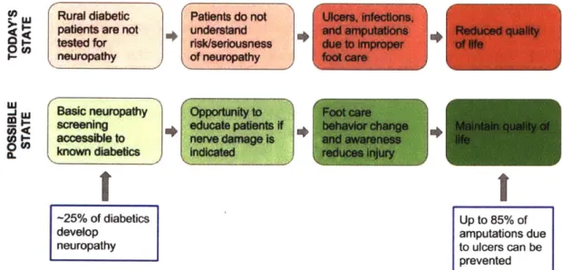
1-1 Value proposition: The mDFA is a tool that identifies the 25% of dia-betics who develop neuropathy, allowing healthcare workers to educate patients and avoid potential life-altering complications such as ulcers, infections, and amputations. . . . . 19
2-1 The nervous system consists of two parts. Central nervous system (CNS): brain and spinal cord. Peripheral nervous system (PNS): nerves [Szym ik, 2011]. . . . . 24 2-2 Diagram of the main components in a nerve cell. The cell body contains
the nucleus. Dendrites receive information from other neurons. The axon conveys the action potential in the form of an electrochemical
impulse. Axon terminals transfer messages to adjacent neurons. . . . 25
2-3 Diagram showing the four types of mechanoreceptors in the skin: Pacinian corpuscle, Meissner corpuscle, Merkel cell, and Ruffini corpuscle [Blausen.com staff, 20141. . . . . 26 2-4 Drawing of a Pacinian corpuscle showing the many layers of lamellae
[G ray, 1918] .. . . . . 27
3-1 Chart provided by NeuroMetrix to be used for clinical interpretation of SNAP amplitude and CV by recorded the NC-Stat DPNCheck device
3-2 Images of the Biothesiometer USA. (a) Inside of a typical biothesiome-ter. This is the inside of the handheld portion of a biothesiometer, with a probe that contacts the patient's foot. An alternating current in the solenoid produces an alternating magnetic field proportional to volt-age, causing the metal spring with plastic probe attached to vibrate. (b) Dial and readout on the Biothesiomter USA. Voltage is manually increased by the dial on the bottom left. When the patient begins to feel vibration, their VPT is indicated by the voltage readout (black tick marks) at the top of the display. . . . . 35 3-3 The six locations on each foot that the ThesioWIN protocol examines. 36 3-4 The ThesioWIN being used to test a patient for neuropathy. The
ThesioWIN's mechanical workings are the same as that of the Biothe-siometer USA, but it includes a digital readout and optional computer connectivity. . . . . 37 3-5 A sample report produced by the ThesioWIN software
[Genesis
MedicalSystem s] . . . . 38 3-6 Graph of reported voltage versus vibration amplitude as specified by
manufacturer-defined conversion equations. The inconsistency between the two devices indicates an error in one or both of the conversion equations. . . . . 39 3-7 Graph of Biothiosiometer USA voltage versus vibration amplitude in
air as measured by a laser Doppler vibrometer. There appears to be a quadratic relationship between voltage and amplitude. The red curve is a least-squares quadratic fit curve, and the green curve represents the predicted displacement based on the provided manual. . . . . 40 3-8 Graph of voltage reading from the built-in Biothesiometer indicator
versus actual measured voltage across the two leads of the coil. Ac-cording to this graph, the display needle is off by a factor of 1.33. . . 40 3-9 A Semmes-Weinstein monofilament is a sharp filament that buckles
4-1 The final mDFA prototype is white and has a black probe. A cable connects the device to the controller and electronics assembly in the black box. . . . . 45 4-2 Examples of bags that CHWs carry as they walk throughout local
villages every day. . . . . 47 4-3 Example of the ERM motor used in the iPhone 4. . . . . 52 4-4 (a) Diagram of a typical LRA. (b) Example bode plot showing a spike
in gain at the natural frequency [Precision Microdrives] .. . . . . 53
4-5 A typical piezoelectric stack actuator is a stack of piezo components with a strain gauge sensor attached [Physik Instrumente]. . . . . 54 4-6 Diagram of a typical solenoid, including a return spring. [Electronics
T utorials]. . . . . 54 4-7 Cross-section of the linear voice coil actuator that was selected for the
mDFA. The magnet assembly (green base and yellow axially magne-tized magnet) is fixed to the housing, while the coil assembly (grey and blue coil holder with orange coil) translates horizontally when current is passed through the coil. . . . . 55 4-8 Examples of early mDFA prototypes that used voice coils with
inte-grated linear bearings. Due to the variable surface on the sole of the foot, these versions were prone to jamming. . . . . 57 4-9 Diagrams of an LVDT. (a) Cut-out view of the inside [Wapcaplet,
2007]. (b) Diagram showing the physics of an LVDT [Fenixdiaz, 2009]. An alternating current is passed through the primary coil. Depending on where the iron core is located, differing amounts of magnetic flux will reach each secondary coil, creating a voltage difference between the secondary coils. . . . . 59
4-10 Photo of an attempt to use a piezo film as a sensor. One end of the film was rigidly attached to white biothesiometer probe, while the other end rested on a screw attached to the biothesiometer housing. As the probe vibrates relative to the housing, the piezo film bends, producing a voltage potential across its leads. . . . . 60 4-11 A linear magnetic encoder uses a series of alternating magnetic poles to
sense detect relative position between a magnetic strip and Hall-effect sensor [AM S, 20131. . . . . 61 4-12 Inside of the final prototype with half of the housing removed. .... 62 4-13 Color-coded CAD model showing the final mDFA prototype. (a)
Ex-ploded view. (b) Cross-sectional view. . . . . 63 4-14 (a) Example reading taken with the Biothesiometer USA, which does
not have a surround support touching the skin. Operator movement during the reading can be seen in the linear migration of wave's neutral axis. The fit wave (solid red) does not match the data (blue dots). (b) Example reading taken with the mDFA with surround support. The wave stays constant because the surround support provides a reference that is attached to the skin. . . . . 65 4-15 Flexures that inspired the probe suspension design. (a) A four-armed
flexure used to mount the coil assembly to the housing and magnet assembly of a voice coil speaker. (b) A large, double-layered flexure that allows free vertical motion and accommodates a small degree of play in other DOF. . . . . 66 4-16 Views of a CAD model of the probe and suspension flexure assembly. 67 4-17 Top row: test rigs used to evaluate flexure performance. Bottom two
rows: a subset of the flexure material and dimensions that were tested. 67 4-18 Block diagram showing the electronic configuration of the mDFA. . . 69 4-19 Final main electronics PCB after soldering. . . . . 69
4-21 Example of the double-window algorithm used to record sensor data on the Arduino until the computer sends a "read" command. The actual window size is approximately half of the remaining RAM. In step 1,
windowO is active and incrementally filled. Once the first window is full, the index is reset and the active window switches (step 2). In step
3, windowi is full and windowO is incrementally overwritten. When the "read" command is received, the non-active window (windowl in
this case) is returned because it has a continuous stream of data. . . . 73
4-22 Screenshots of the computer application. (a) When using the The-sioWIN or Biothesiometer USA, the operator manually controls vi-bration and manually enters the voltage reading in the top-left box each time. (b) When using the m-DFA, the vibration amplitude is computer-controlled, and vibration level is indicated by the vertical progress bar to the left of the graph. . . . . 76 4-23 Screenshots of the Android mobile application developed as a proof-of
concept. (a) Ther user is prompted to establish a Bluetooth connec-tion between the phone and mDFA. (b) Screen to input patient health information. (c) The app guides the operator through testing the 12 points on the feet. Each time the patient feels vibration, they push the large red "Stop" button, which (d) Records and displays the sensor output, which is vibration amplitude in rm. . . . . 78
5-1 Biothesiometer USA retrofit with an AS5311 sensor and Arduino. . . 80
5-2 Stimulus vs measured vibration amplitude with each device. (a) Bio-thesiometer USA: R2 = 0.55. (b) mDFA: R2 = 0.42. . . . . 85
5-3 Plots of (a) Nerve conduction amplitude vs. measured VPT amplitude, and (b) Nerve conduction velocity vs. measured VPT amplitude. In each plot, blue and red represent the Biothesiometer USA and mDFA, respectively. Dots are data points and lines are least square fit lines. Each of the datasets have clear, but not strong, correlations. . . . . . 85
5-4 (a) Plot of nerve conduction amplitude vs. velocity in each of the 44 feet. Neuropathy level was determined based on the reference chart (b) provided by NeuroMetrix. There were 21 normal feet, 17 feet with mild neuropathy, 6 feet with moderate neuropathy, and no feet with severe neuropathy. The number of dots on the graph in (a) appears to be less than the number of feet due to overlap in NCA and NCV measurements in some feet. . . . . 86 5-5 Box-and-whisker plots of Biothesiometer USA (blue) and mDFA (red)
VPTs based on neuropathy levels determined by the DPNCheck. The actual values in each plot are listed in Table 5.1. The dots within each box represent the corresponding mean value. (a) Plot of Biothesiometer USA VPTs. (b) Plot of mDFA VPTs. (c) Side-by-side plot with the same information that allows for a visual comparison of thresholds from each device. . . . . 87
List of Tables
3.1 Comparison of the overall advantages and disadvantages of existing devices and the m-DFA. . . . . 31 3.2 A summary of previous studies that contained different devices,
meth-ods, and results. . . . . 42
4.1 Functional requirements and design parameters for the m-DFA. . . 46
4.2 Summary of actuator options and their properties, as well as specific reasons why certain actuators were eliminated. Resolution, efficiency, and voltage numbers obtained from [Electronics Tutorials, Precision Microdrives, Bala, 2015, Thorlabs] . . . . 51 4.3 Pugh chart weighing actuator options, with LRA chosen as the datum.
Based on this assessment, a linear voice coil actuator was chosen. . . 51 4.4 Moticont LVCM-016-013-01 voice coil actuator specifications. . . . . . 58 4.5 Bill of materials for the electronics. Prices listed are costs for
small-quantity prototypes. . . . . 70 4.6 Arduino protocol for receiving simple commands from a computer or
mobile phone. The computer can either ask the Arduino to return a set of sensor readings, or change the vibration level. . . . . 71 5.1 Summary of reults from the study. 44 feet were separated into normal,
mild, and moderate neuropathy based on NCS. For each category and each device, the mean, standard error and 95% confidence interval are shown. The upper adjacent, 75th percentile, median, 25th percentile, and lower adjacent define the boundaries in the box plots in Figure 5-5. 84
Chapter 1
Introduction
Healthcare infrastructure in much of the developing world has historically focused on treating infectious diseases such as HIV/AIDS, respiratory infections, and tuberculo-sis. However, as average lifespans, quality of life, and access to healthcare increases around the world, it has become increasingly apparent that non-communicable dis-eases (NCDs) also need to be addressed as a global health problem. For the first time in history, more people are dying of NCDs than infectious diseases. According to the World Health Organization's 2014 global status report on non-communicable dis-eases, NCDs are the leading cause of death worldwide, and nearly 75% of NCD-related deaths occur in low- and middle-income countries [World Health Organization, 2014]. Diabetes is an example of a non-communicable chronic disease that now pervades developing countries as much as their developed counterparts. In fact, India has over-taken the United States as the "Diabetes Capital of the World" [Joshi and Parikh, 20071. When patients are properly treated and implement lifestyle changes, their con-dition (as well as complications that may arise) is manageable and they can expect to enjoy a relatively unaffected day-to-day life. However, untreated complications often develop into serious health problems that can lead to severe impairment and decrease in quality of life. The primary diabetes complications are retinopathy (eye dam-age), nephropathy (kidney damdam-age), neuropathy (nerve damdam-age), and cardiovascular disease.
(DSPN),
which is nerve damage that typically leads to loss of touch sensation in the feet. DSPN is also known as distal symmetric neuropathy, distal symmetric sensorimotor polyneuropathy, distal symmetric peripheral neuropathy, and diabetic sensorimotor polyneuropathy. Up to 25% of diabetic patients will develop a foot ulcer as a result of DSPN [Shankhdhar et al., 2008], and 5-24% of those ulcers will lead to amputation [Alexiadou and Doupis, 2012]. In fact, ulcers precede 85% of diabetic amputations [Pradeepa et al., 2008].1.1
Motivation
DSPN causes patients to lose sensation in their feet, which is especially problematic in rural areas where locals frequently walk around barefoot or with minimally protective sandals. The combination of lack of pain with an impaired immune response can cause a small cut or ulcer to become infected and in the worst cases require amputation. This can be devastating to people whose livelihoods often rely on their ability to walk. A patient history of foot ulcers increases the likelihood of amputation by a fac-tor of 36, and at least half of foot ulcers in neuropathic diabetics can be prevented by appropriate treatment and patient education
[Gow
and Moore, 2014],[Shankhd-har et al., 20081. As with many symptoms and complications of diabetes, the most effective approach to controlling DSPN is glycemic management. In addition, pre-venting further foot damage can be achieved by managing the effects of neuropathy through daily foot care and inspection, immediate treatment of even minor foot cuts and injuries, and protective footwear [Ali, 2003]. In many rural populations, diabetic patients with DSPN are often not concerned with foot damage if they are not expe-riencing pain, and are sometimes even unaware of their injuries. It is essential that they are identified, made aware of the risk of further damage or amputation, and taught proper foot care practices [Shankhdhar et al., 2008].
For a variety of reasons that will be discussed later in this thesis, diabetic patients in most parts of the world are currently not being tested for neuropathy, leaving them vulnerable to life-altering injuries. The purpose of this research was to develop a
de-vice called the Mobile Enabled Diabetic Foot Analyzer (mDFA) that can be operated by minimally trained workers in flexible settings to screen for diabetic neuropathy. Identifying patients who display signs of neuropathy will allow doctors to focus their efforts on educating those patients on how to curb the effects of the condition and prevent it from worsening. Figure 1-1 summarizes the current state and affects of di-abetic neuropathy in rural India, and the benefits that identifying neuropathy would provide.
L Rural diabetic Patients do not Ulcers, infections,
patients are not understand and amputations Reduced quality - tested for risk/seriousness due to Improper of Ife
neuropathy of neuropathy foot care
Basic neuropathy Opportunity to Foot care
screening educate patients If behavior change inta qualty of
accessible to nerve damage is and awareness life
known diabetics indicated reduces injury
-25% of diabetics Up to 85% of
develop amputations due
neuropathy to ulcers can be
prevented
Figure 1-1: Value proposition: The mDFA is a tool that identifies the 25% of diabetics who develop neuropathy, allowing healthcare workers to educate patients and avoid potential life-altering complications such as ulcers, infections, and amputations.
1.2
Community Health Programs in India
The mDFA was developed in partnership with Agada Hospital in Chennai, Tamil Nadu, India. Agada Hospital specializes in diabetes treatment and also operates a community health program in surrounding rural villages in Tamil Nadu.
In 2003 the Tamil Nadu government passed a Health Policy that "aims to.. .combat non-communicable diseases and accidents, strengthen management of health systems
and increase effectiveness of the public sector healthcare services. The policy focuses on improving the health status of the general population, which special emphasis on low-income, disadvantaged and tribal communities" ITNHSPI. The Tamil Nadu Health Systems Project (TNHSP) was created to carry out the Health Policy. In addition to the goals described above, the TNHSP also aims to create "awareness about non-communicable diseases and screening for those conditions." It operates through Primary Health Centers (PHCs) that are dispersed throughout the state and offer free lab services, medications, and diabetes treatment.
To extend the reach of TNHSP, the National Network for Organ Sharing (NNOS) recently developed the Rural Non-Communicable Disease Prevention Program (R-NCDPP) under the direction of Dr. Mohan Thanikachalam. Dr. Thanikachalam is the founder of NNOS, director of Agada Hospital (the partner hospital of R-NCDPP), and one of the primary advisors to the mDFA project. According to the R-NCDPP proposal, the program is "a cost-effective, scalable Public-Private Partnership (PPP) model for case finding, care linkage and treatment compliance for NCDs within exist-ing rural healthcare infrastructure." Through R-NCDPP, local paid community health workers (CHWs) are trained in basic understanding and treatment of diabetes. These CHWs perform regular home visits to villagers who have already been identified to suffer from diabetes and/or hypertension. CHW productivity is monitored daily by the project coordinator at Agada Hospital. The coordinator also travels to the villages each week to check up on CHWs and provide training and support.
CHWs use a mobile application called CommCare that is part of an m-Health cloud-based platform (developed in conjunction with the software company Dimagi) to collect data and educate patients. The use of mobile technology also serves to stan-dardize care administered from person to person. Through the m-Health application, patients also receive SMS messages with reminders and provider messages.
The mDFA was designed with CHWs in mind. The R-NCDPP CHWs in particular were interviewed and consulted often throughout the design process. These women periodically tested various prototypes and provided their feedback. Designing the device to be operable in the lowest-resource settings by minimally trained workers
allows it to have a potentially far-reaching impact in larger clinics and hospitals, private primary care offices, and other community health programs throughout India and the world.
1.3
Thesis Scope
Tackling the problem of diabetic neuropathy requires various levels of intervention, and is not as simple as prescribing a medication or treatment that is guaranteed to cure or reverse the condition. Unfortunately, once neuropathy has begun to develop it is not reversible. However, its progress can be slowed though glycemic management and its effects can be controlled by proper foot care. For patients whose foot sensation is impaired, it is essential that they are educated on the seriousness of the condition and how best to prevent wounds and ulcers. In much of the developed world, foot problems are a well-known complication of diabetes and people know to watch out for neuropathy. However, in developing areas where diabetes has become common but awareness has not yet caught up, patients are often neither aware of, nor concerned about neuropathy. Because behavior change and proper foot care is the only way to prevent neuropathy-related morbidity, it is essential that patients understand the reality and seriousness of neuropathy.
The purpose of the mDFA project was to design a device that can screen for diabetic neuropathy in the context of resource-constrained areas around the world, particularly India. The hope is to identify and treat the onset of DSPN early to stop the "firefighting" that often happens when patients present at hospitals with already
severely infected feet that are much more difficult to treat.
This first half of this thesis sets the stage for the mDFA by describing the patho-physiology of diabetic neuropathy, listing existing technology to test for neuropathy, and discussing the unique challenges of diagnosing and treating neuropathy in low-resource settings. The second half of this thesis outlines the design process, presents preliminary clinical data, and discusses ongoing and future plans to manufacture and distribute the system.
Chapter 2
Distal Symmetric Polyneuropathy
(DSPN)
Up to 50% of diabetic patients have one or more types of neuropathy [Quan, 2017], which in the simplest term means nerve damage. There are two main types of neu-ropathy in diabetic patients: sensorimotor and autonomic. Sensorimotor neuneu-ropathy is the most common form of nerve damage, and is the focus of this thesis. It affects the sensory and motor nerves and causes either positive symptoms like hypersensitivity and pain, or negative symptoms such as loss of sensation. Autonomic neuropathy af-fects the cardiovascular, urogenital, gastrointestinal, pupillomotor, thermoregulatory, and sudomotor systems [Freeman, 20141.
For clarity and consistency throughout this thesis, diabetic sensorimotor neuropa-thy will be referred to as distal symmetric polyneuropaneuropa-thy (DSPN) or diabetic
neu-ropathy. Other synonymous terms that can be found throughout literature are distal
symmetric sensorimotor polyneuropathy, diabetic sensorimotor neuropathy, and dia-betic peripheral neuropathy.
The words in the variations of DSPN names are useful in understanding the char-acteristics that define this type of neuropathy and set it apart from others:
* Distal - Begins farthest away from the brain (in the toes) and progresses up the body.
" Symmetric - Affects both the left and right side equally. * Sensorimotor - Affects sensory and motor nerves.
" Polyneuropathy - Disorder of the peripheral nerves that affects both sides.
2.1
Sensory Nerve Physiology
In order to understand what goes wrong when nerves are impaired, it is useful to understand the normal anatomy and function of sensory nerves.
The nervous system controls communication and function throughout the body and is made of two parts: the central nervous system (CNS) and the peripheral nervous system (PNS). The CNS comprises the brain and spinal cord. The PNS consists primarily of nerves that branch out from the CNS into the rest of the body (Figure 2-1). DSPN affects sensory nerves in the peripheral nervous system.
Brain
Spinal Cord
Nerves
Central Nervous System (CNS) Peripheral Nervous System (PNS)
Figure 2-1: The nervous system consists of two parts. Central nervous system (CNS): brain and spinal cord. Peripheral nervous system (PNS): nerves [Szymik, 2011].
Nerve cells, also called neurons, consist of four main components: (1) the cell body, which contains the nucleus, (2) dendrites, (3) axon, and (4) axon terminals
(Figure 2-2). A dendrite is stimulated when it receives a message from another neuron. That message is transmitted through the axon as an electrochemical impulse called an action potential. In order to propagate this action potential from one neuron to the next, chemical messengers called neurotransmitters are released by the axon terminal of one neuron, travel through the synaptic cleft (small space between adjacent neurons), and are received by dendrites of nearby neurons. An axon is typically significantly longer than any other structure in a neuron. Longer axons are usually insulated by fatty cells that make up a myelin sheath, whose function is analogous to plastic insulation around an electrical wire. A collection of axons bundled together forms a nerve.
axon terminals
cell body dendrites (output)
(input)
Q~inPotent:8
nucleus axon
Figure 2-2: Diagram of the main components in a nerve cell. The cell body contains the nucleus. Dendrites receive information from other neurons. The axon conveys the action potential in the form of an electrochemical impulse. Axon terminals transfer messages to adjacent neurons.
There are two broad categories of nerves. Sensory nerves transmit signals to the brain relating to the five senses: taste, sight, touch, smell, and hearing. Motor nerves transfer commands from the brain to stimulate muscles. Interneurons connect sensory and motor neurons.
Most senses use local, dedicated organs to collect information. Photoreceptors in the cornea of an eye detect light, receptors within the ear are stimulated by vibration caused by rapid pressure changes in air, and the nose and mouth detect smell and taste respectively. In contrast, touch sensations occur throughout the body, both superficially on the skin and deep within the body.
Mechanoreceptors are nerve endings throughout the body that detect touch by responding to mechanical stimuli. Cutaneous mechanoreceptors are located in the skin and identify touch, pressure, vibration, and temperature. The brain is able to decipher what type of sensation was felt based on the type of mechanoreceptor that sends the signal: Pacinian corpuscle, Meissner corpuscle, Merkel cell, or Ruffini cor-puscle (Figure 2-3). Pacinian corcor-puscles are responsible for detecting rapid vibrations in the range of 100 - 500 Hz
[Temlett,
2009]. Meissner corpuscles are most sensitive to vibrations within the range of 30 - 50 Hz that accompany actions such as feeling a textured surface [Purves et al., 2001]. Merkel cells are responsible for the sensation of steady light touch. Ruffini corpuscles respond to skin stretching and contribute to proprioception.The primary structural elements of Pacinian corpuscles are a series of concen-tric layers of lamellae (Figure 2-4), which appear similar to the layers of an onion. Mechanically, the lamellae and their interconnections act as springs, and the fluid between the lamellar surfaces acts as dashpots. Together, these components can be modeled as a network of springs and dashpots that filter out low-frequency vibra-tions [Loewenstein and Skalak, 1966, Biswas et al., 2015a,b]. Thus, the magnitude of the action potential when Pacinian corpuscles are stimulated depends on vibration frequency and displacement of skin depressing the nerve.
Free nerve endings
-Merkel cell
(Tactile disc)
Tactile corpuscle
(Meissner's corpuscle)
Ruffini corpuscle
Root hair plexus Larnellated corpuscle
(Pacinian corpuscle)
Figure 2-3: Diagram showing the four types of mechanoreceptors in the skin: Pacinian corpuscle, Meissner corpuscle, Merkel cell, and Ruffini corpuscle [Blausen.com staff, 2014].
Figure 2-4: Drawing of a Pacinian corpuscle showing the many layers of lamellae [Gray, 1918J.
2.2
Symptoms and Progression
DSPN occurs in both type 1 and type 2 diabetic patients [Tracy et al., 2008] and affects the right and left sides of the body equally. It is a disorder of the peripheral nerves, so its initial onset affects the toes, where nerve axons are located farthest from their cell bodies in the spine [Reeves and Swenson, 20081. Symptoms then progress up the feet, calves, and legs. Patients tend to experience numbness and tingling in their hands around the same time that the neuropathy reaches their knees [Ali, 2003, Bansal et al., 2006]. Thus, when performing sensory diagnostic and screening tests, the optimal location is the sole of the foot.
Patients with neuropathy experience one or both of two opposite symptoms: painful or burning sensations in response to small or non-existent external stimuli (positive symptoms), and/or numbness, tingling, and lack of sensation (negative symptoms) [Gow and Moore, 2014]. In general, positive symptoms are associated with small nerve fibers, whereas negative symptoms are associated with large nerve fibers. However, nerve damage in both small and large fibers can produce positive and negative symptoms. Damage to small nerve fibers can cause decreased pain and thermal perception. Large nerve fiber damage can reduce vibration sense and proprioception [Reeves and Swenson, 2008]. DSPN tends to affect large myelinated fibers first, followed by the smaller myelinated and unmyelinated fibers. Large-fiber vibration sense is usually the earliest to be impaired, followed by reduced pin-prick, thermal, and light-touch sensitivity. Proprioception and motor function can also be affected, but are more difficult to detect.
2.3
Treatment
Treating diabetic neuropathy is challenging because it requires consistent, prolonged patient compliance. A variety of drugs are effective in lessening pain in painful neu-ropathy [Calabek et al., 2014], but there is little evidence that pharmacological treat-ments can reverse DSPN once it has developed
[Garrow
and Boulton, 20061. Thus, DSPN treatment focuses on glycemic management and proper foot care.Over the span of multiple years, glycemic control can prevent worsening of or occasionally improve diabetic neuropathy [Tesfaye et al., 20101. Because controlling blood sugar also decreases other diabetes symptoms and complications, it is one of the first methods that doctors recommend to combat neuropathy.
Beyond glycemic management, proper foot care is essential in managing DSPN on a day-to-day basis and preventing wounds. Patients should wear closed-toe shoes that protect the feet from sharp objects, or sandals at a minimum, when walking outside. Footwear specifically designed to offload pressure points is ideal. Shoes and orthotics are available in both off-the-shelf and custom-made versions. Patients should inspect their feet for calluses, cuts, and wounds daily. An active ulcer or infection needs to be treated immediately by a medical professional [Gow and Moore, 20141.
An ulcer is difficult to treat in diabetics because they are prone to slow healing due to an impaired immune response, which increases the risk of amputation. Thus, diligent, long-term foot care and ulcer prevention is the best approach to treating
DSPN.
2.4
Financial Burden of Neuropathy
Neuropathy is the most common diabetes complication, with 24.6% of diabetics devel-oping DSPN at some point. In comparison, 16.6% of diabetics develop retinopathy [Kaveeshwar and Cornwall, 2014]. In India, patients with diabetes spend an av-erage of Rs. 8,822 annually on diabetes-related expenses, 3.2% of which is spent on laser treatment for retinopathy [Chandra et al., 2014]. This gives an average
of Rs. 282.3 spent on laser treatment per person per year. Assuming that treat-ment for neuropathy costs roughly the same as that for retinopathy, we can
esti-mate that the cost of neuropathy is Rs. 282.3 x p 24.6 16.6% = Rs. 418.35 per person per
year. There are 62 million diabetics in India [Kaveeshwar and Cornwall, 2014]. 62 million x Rs. 418.35 ~ Rs. 26 billion ~ $239 million per year.
On the patient level, the financial burden of neuropathy depends on many factors. Early in the clinical course of neuropathy when a patient has been diagnosed but has not yet developed any wounds requiring treatment, custom orthotics or special shoes may be the only major costs. An infected wound accrues cost when treatment is needed. In the most extreme cases, mobility limitations caused by amputations can lead to job loss. Thus, the most cost-effective way of relieving the financial bur-den of neuropathy is simple preventative foot care measures to reduce the occurrence of ulcers. Screening for DSPN will allow healthcare workers and doctors to iden-tify patients for whom education and close monitoring are most needed to prevent progression of DSPN.
Chapter 3
Existing Technology
Various methods and devices exist to diagnose or screen for neuropathy, each with its own advantages and disadvantages. The gold standard for assessing nerve health is the nerve conduction study (NCS), which measures a nerve's response to an electrical stimulus. Vibration perception threshold (VPT) is a psychophysical test that requires a patient to indicate when they feel a vibrating stimulus. Punch skin biopsy is the most accurate way to determine the pathology of small nerve fibers. The monofila-ment and tuning fork are both inexpensive instrumonofila-ments that can be used to quickly and crudely gauge a patient's sensation. However, they are binary tests and therefore give no insight into the severity of a patient's sensation loss. This chapter introduces these diagnostic methods and explains the advantages and disadvantages of each. It also explains the logic by which VPT was chosen to best fit the requirements and chal-lenges of screening for sensory neuropathy in low-resource, poorly connected areas. A summary of existing devices is shown in Table 3.1.
Table 3.1: Comparison of the overall advantages and disadvantages of existing devices and the m-DFA.
Method Reliable Quantitative Cost Portable
Nerve conduction /// // $$$$ X
Biothesiometery / / $$$ X
Punch skin biopsy // // $$$$ X
Tuning fork/monofilament / X $ /
3.1
Gold Standard: Nerve Conduction Study
The gold standard for diagnosing DSPN is nerve conduction velocity obtained through sural nerve conduction studies (NCS) [Bril and Perkins, 20021. NCS is the only non-invasive method in which nerve health can be directly evaluated.
NCS evaluates nerve function by producing a small, non-invasive electrical stimu-lus through a surface electrode attached to the skin and measuring sural nerve action potential (SNAP) amplitude and conduction velocity (CV) of the response in another electrode attached a known distance away [Levinson, 2014]. The SNAP amplitude and conduction velocity are also commonly referred to as nerve conduction amplitude (NCA) and nerve conduction velocity (NCV), respectively. Motor and sensory nerves throughout the body can be assessed, but the standard nerve targeted in diagnosing DSPN is the sural nerve. The SNAP amplitude depends on the number of sensory nerve fibers able to conduct impulses and is decreased by axon loss or damage. The SNAP CV is calculated based on the time latency between the two electrodes and decreases with nerve demyelination
[Wilbourn,
19941. Together, SNAP amplitude and CV can be used to diagnose large fiber neuropathy by plotting them on a graph as in Figure 3-1 and determining which section they fall into.Unfortunately, NCS is painful, costly (approximately $60 per limb in India), time-consuming (up to 90 minutes per limb), requires specialized equipment that is unavail-able in most hospitals and clinics, and is not reliunavail-able unless performed by a proficient neurologist [Tesfaye et al., 20131, [Lee et al., 2014]. In addition, because NCS is only sensitive to large fiber nerves, it is not useful in evaluating small fiber nerves.
3.2
Vibration Perception Threshold
Quantitative Sensory Testing (QST) is a psychophysical testing method in which a patient is exposed to increasing levels of stimulus and asked to respond when they first sense the stimulation. Vibration perception threshold is a type of QST that gives a quantitative measure of a patient's ability to sense vibration. Although it has
Figure 3-1: Chart provided by NeuroMetrix to be used for clinical interpretation of SNAP amplitude and CV by recorded the NC-Stat DPNCheck device [NeuroMetrix]
not been largely adopted in the United States (likely because NCS is an available option), VPT is the primary measure by which DSPN is diagnosed in many hospitals in the developing world. Studies have found that VPT is correlated to NC velocity in diabetic patients, and that abnormal VPT indicates an increased risk of developing ulcers, validating its use as a diagnostic device in the clinical setting [Bril and Perkins, 2002, Garrow and Boulton, 2006, Coppini et al., 1998, Cheng et al., 1999, Martin et al., 2010, Bril et al., 1997, Gregersen, 1968].
Because vibration sense is one of the first tactile senses to be affected by DSN; it is related to usually painless large fiber dysfunction (for which patients are significantly less likely to seek treatment); and vibration sense can be assessed non-invasively, painlessly, quickly, objectively, and without extensive equipment, this thesis focuses on developing a vibration-based device for early polyneuropathy screening.
Abnormal VPTs in diabetic patients have been shown to be a good predictor of foot ulcer development and are correlated with the presence of neuropathy [Coppini et al., 1998, Cheng et al., 1999, Nicholls et al., 2009]. However, a review of the literature and existing instruments used to determine VPT reveal the need for a
Nerve Conduction Reference Ranges
32-MU Neupadw omnal M~d euraalft Nerve Condtiotlom
2 Moderate Neuropathy
I-I
203 30 40 50 0 Conduction Veaocity (m/s)
Normal I Noral Normal
Wld I Normal Abnormal
U Abnormal Normal or Abnormal Undatactabla
more consistent and accurate device that reports results in terms of displacement. In addition, existing devices are outdated and power-hungry, as they require an outlet to run. The small forces and displacements required to stimulate Pacinian corpuscles indicate that a portable, battery-operated device is sufficient to determine degree of VPT, even in severely neuropathic patients. Thus, this thesis focuses on developing a portable device that can accurately measure and track VPT in diabetic patients with and without DSN.
3.2.1
Biothesiometer
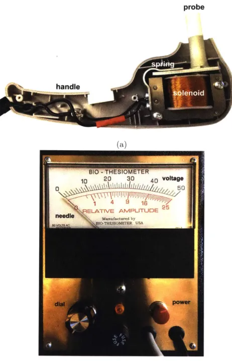
Vibration perception threshold is measured using a biothesiometer, which has a fingertip-sized probe that vibrates at a fixed frequency and variable amplitude (Fig-ure 3-2a). An operator places the probe at a testing site on the foot and applies a pressure approximately equal to the weight of the handheld portion of the device. The operator then turns a dial, which increases the vibration amplitude until the patient indicates that he feels the vibration. This gives the patient's VPT for that location of the foot. This procedure is repeated at several other locations on each foot.
The Biothesiometer USA (Bio-Medical Instrument Co., Newbury, OH) is the most-used device in biothesiometric studies available in the literature. A photo of the inside of the device with labeled components is shown in Figure 3-2a. An electromagnet that consists of a wire coil wrapped around an iron core is connected to a mains power supply. The alternating current produces an alternating magnetic field, which acts on a cantilevered steel plate. The attraction force of the steel plate to the coil increases with increasing magnetic field strength, so that it vibrates at twice the mains
frequency (2 - 60Hz = 120Hz in the U.S. and 2 - 50Hz = 100Hz in India). Attached to
the vibrating steel plate is a 0.5in diameter plastic probe that is placed on the skin. Vibration intensity is varied by manually turning a dial. An analog needle indicates the voltage that is being inputted into the coil (Figure 3-2b).
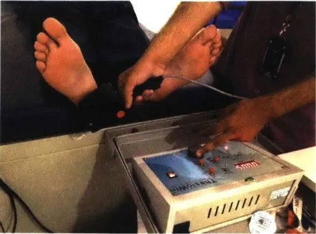
One of the most common biothesiometers used in Indian hospitals is the The-sioWIN (Recorders and Medicare Systems Pvt Ltd., Panchklula, India), which is
probe
(a)
(b)
Figure 3-2: Images of the Biothesiometer USA. (a) Inside of a typical biothesiometer. This is the inside of the handheld portion of a biothesiometer, with a probe that contacts the patient's foot. An alternating current in the solenoid produces an alter-nating magnetic field proportional to voltage, causing the metal spring with plastic probe attached to vibrate. (b) Dial and readout on the Biothesiomter USA. Voltage is manually increased by the dial on the bottom left. When the patient begins to feel vibration, their VPT is indicated by the voltage readout (black tick marks) at the top of the display.
shown being used in Figure 3-4. The ThesioWIN is used at Agada Hospital, where we performed studies in diabetic patients to compare the Biothesiometer USA, mDFA, and nerve conduction studies. It is the primary device that doctors at the hospital use diagnose diabetic neuropathy today. The mechanisms inside the ThesioWIN that produce vibration are identical to Biothesiometer USA. The main difference between the two devices is that the ThesioWIN has a digital readout of voltage, and has the option to connect to a computer program that records the VPT for each foot and produces a report. Built into the software is a protocol that specifies six specific points on each foot to test (Figure 3-3).
..o0
0@.
3.2.2 Reporting Units and Reliability
Although the biothesiometer provides quantitative data on patients, the VPT, which tends to be reported in volts, is not standardized or well-calibrated, causing reported sensory thresholds to vary from brand to brand and even device to device
(see
Table 3.2). For example, the manufacturer of the ThesioWin(Recorders
and Medicare Sys-tems Pvt Ltd., Panchklula, India) indicates that a VPT of 15 V signals the onset of neuropathy, whereas the Biothesimeter USA(Bio-Medical
Instrument Co., Newbury, OH), which is the most-used device in biothesiometric studies, produces a similar vi-bration amplitude at 24.5 V IPourhamidi et al., 2014j. The manufacturer of the The-sioWIN gives a conversion equation from voltage to vibration displacement amplitudeFigure 3-4: The ThesioWIN being used to test a patient for neuropathy. The The-sioWIN's mechanical workings are the same as that of the Biothesiometer USA, but it includes a digital readout and optional computer connectivity.
of A = 2V. The Biothesiometer USA manual provides an equation of A = 0.01V2
(where A is the amplitude in units of microns, pm, and V is the voltage in units of volts, V). Given that the mechanisms inside the two devices are the same, it does not make sense that the conversion equations would differ by an order. Thus, either one or both of the equations must be wrong.
To understand the differences in reported measurements using the Biothesiometer USA and ThesioWIN, we used each device to find the VPT at each of the 12 sites on the sole of the feet of five subjects (two healthy and three diabetic). The relevant equation provided by each manufacturer was used to convert reported voltage to displacement amplitude. As seen in the plot in Figure 3-6, these conversion equations produce vastly different thresholds in microns, indicating that one or both of the manufacturer-provided conversions is incorrect. The large differences in reported displacements in two very similar devices points to the need for a standardized method of reporting and instrument calibration.
To determine whether the voltage-amplitude relationship is first or second-order, a laser Doppler vibrometer was used to measure the Biothesiometer USA probe
vibra-Universal Hospitals
Magd Cour Bashabo, Hrlbsd.Ph.No.6A4800I TheoW n
Patent Details Teat Details
Patient Name: Dae :03/1012016 Time : 17: 23: 52
Vibration TeSt Sex: MAge:35Yra. Wt:75kgs Ht:175cm Report Date: 20 / 01 / 2017
BSA: 1.903 m BMI : 24.49 Kgm 2 Report Time: 12: 53: 32
12.02 V 24.04 pm 9.79 V 6.11 V 19.58 pm 12.22 pm 12.41 V 24.82 pm 9.59 V 19.18 pm 11 .37 V 22.74 pm Interpretation
Right Foot Left Foot
Toe : Normal ToO : Norm
First Metatarsal Head : Normal First Metatarsal Head : Norm Third Metatarsal Head : Normal Third Metatarsal Head : Norm
Fifth Metatarsal Head : Normal Fifth Metatarsal Head : Norm
Instep : Normal Instep : Norm
Heel :Normal Heel :Norm
This may be clinically co-related
C2003-08 Genesis Medical Systems Pvt. Ltd.
9.79 V 19.58 pm 8.54 V 11.82 V 17.08 prn 23.64 pm 9.82 V 19.64 pm 12.52 V 25.04 pm 12.05 V 24.10 pmn al ai ai al __________ al Physician al www.geneslsmecdicals.comi
Figure 3-5: A sample report produced by the ThesioWIN software
[Genesis
Medical Systems]100 1_1_1_1_1_1_1 * ThesioWin (A = 2V) 90 * Biothesiometer USA (A =0.0 1*V2 80 - S70-60 -, 50 40-20 -3 207 10- 0 a .. 0 L_ I0 ---0 5 10 15 20 25 30 35 40 45 50 voltage [V]
Figure 3-6: Graph of reported voltage versus vibration amplitude as specified by manufacturer-defined conversion equations. The inconsistency between the two de-vices indicates an error in one or both of the conversion equations.
tion amplitude as it vibrated in air at varying voltages. Results are shown in Figure
3-7, which indicates a roughly quadratic relationship between voltage and amplitude.
The order of the curve is consistent with the Biothesiometer USA manual. However, the coefficient in front of the squared term is noticeably different.
To test the reliability of the analog voltage dial in the Biothesiometer USA, the voltage across the ends of the coil was measured as the dial was slowly turned. The graph in Figure 3-8 reveals that the dial is off by a factor of 1.33. This further reinforces the danger of relying on the analog dial and conversion equation to report VPT, and reinforces the need for a sensor to measure actual vibration amplitude.
Although voltage is related to the energy delivered to the skin, the amplitude of displacement depends on the force produced by the mechanics of the device, the dynamic impedance of the skin, and the pressure with which the operator presses the probe onto the skin. Furthermore, the vibration intensity that a biothesiometer produces at a particular voltage varies from device to device (even among the same brand) because tiny variations in manufacturing and assembly propagate through
80 70 -E 60 50 40 30 20 10 0 -IA0 Vibrometer measured - - Fit curve: A = 0.029147V2 + -0.045466V + -0.31275
- Predicted displacement (according to device manual) .
-,
I
0 5 10 15 20 25 30 35 40 45 50
voltage [V]
Figure 3-7: Graph of Biothiosiometer USA voltage versus vibration amplitude in air as measured by a laser Doppler vibrometer. There appears to be a quadratic relationship between voltage and amplitude. The red curve is a least-squares quadratic fit curve, and the green curve represents the predicted displacement based on the provided manual.
0 5 10 15 20
voltage reading [V]
25 30 35
Figure 3-8: Graph of voltage reading from the built-in Biothesiometer indicator versus actual measured voltage across the two leads of the coil. According to this graph, the display needle is off by a factor of 1.33.
- Fitline: y =1.328x +0.78827 * Measured 50 45 40 ,35 30 > 25 -a 20 E 15 10 5 n -10
the device and have a magnified effect at the tip. Thus, only reporting the voltage does not give us the complete picture of what is going on at the level of the physical vibration. Recognizing the inconsistencies among devices and studies involving VPT reported in volts, Goldberg and Lindblom developed a standardized approach to determining VPT and proposed that results be reported in microns to reflect actual probe movement to allow for congruity across devices [Goldberg and Lindblom, 1979].
3.2.3
Examination Method
Several studies have attempted to characterize reference VPTs in healthy and neu-ropathic populations (see Table 3.2). Although most studies use the Biothesiometer USA, the large range of testing approaches and lack of a standardized process makes comparing results across studies difficult. The most common examination method is the mean of three VPT readings on the plantar surface of the great toe. Table 3.2 summarizes VPT locations, methods, devices, and thresholds presented in published studies throughout the literature.
3.2.4
Vibration Frequency
Pacinian corpuscles, the mechanoreceptors that respond to vibration, are most sen-sitive around the 100-300 Hz range, and VPT tends to increase at lower and higher frequencies [Temlett, 2009]. Due to the physical structure of biothesiometers, their probe tips vibrate at twice the frequency of the alternating current from the outlet: 120Hz in the U.S., which is within the sensitive range of Pacinian corpuscles. Unlike displacement amplitude, frequency has been measured to be accurate and consistent across biothesiometers at either 100 Hz or 120 Hz, depending on geographic location.
3.2.5
Impact of Age, Gender, Weight, and Race
In normal populations, VPT increases logarithmically with age [Nielsen, 1972]. One study calculated an age-adjusted "standard deviation" score, equal to the number of standard deviations a patient's threshold is away from the mean of healthy subjects
Table 3.2: A summary of previous studies that contained different devices, methods, and results.
Author and Year Location Reporting method Device used Thresholds
Young et al. 1993 Plantar surface of great toe Mean of 3 readings Biothesiometer USA, 29.9 15.2 V, Neurothesiometer 26.2 13.4 V
(heal Tochman-Gawda et al. Toetip, metatarsus, dorsum of Single measurement at each site Biothesiometer USA 2007 the foot, external ankle
Temlett 2009 Thumb, hallus, pmximal Mean of "perception threshold" Biothesiometer USA
tibia, distal tibia (VPT) and "disappearance
threshold" (VDT) for each site
Pourhamidi et al. 2014 Medial malleolus Not specified Biothesiometer USA 24.5 V cutoff (82% sensitivity, 70%
Kumar et al. 1991 Plantar surface of great toe Mean of 3 readings Biothesiometer USA Normal: 10.6 6.7 V
Abnormal: 22.8 12.7 V (78.6%
sensitivity, 93.4% specificity) Very abnormal: 32:1-143V
Coppini et al. 1998 Pulp of thumb, great toe, and Standard deviation score based on Biothesiometer USA Normal: 27.2 7.9 V
medial malleolus log of voltage reading against age Abnormal: 28.5 12.7 V (70%
sensitivity, 70-72%, specificity)
van Deursen et al. 2001 Plantar surface of hallux and VPT and VDT measured 3 times, Biothesiometer USA Normal: 15 8 V (hallux), 10 7 V (heel)
heel mean of highest and lowest of Neuropathic: 47 5 V (hallux),43 I I V
those 6 measurements was (heel) ...
reported
Williams et al. 1988 Medial malleolus and plantar Mean of 6 readings Biothesiometer USA
surfae o reat toe
Pradeepa et al. 2008 Plantar surface of great toe Mean of 3 readings Biothesiometer USA Abnormal: 2 20 V (which was the mean + 2 SD in healthy patients, aged 20-45
Armstrong et at. 1998 Planta urfe of toe Mean of 3 readings Biothesiometer USA Used 25 V cutoff
Bril et al. 1997 Plantar surface of great toe Mean of 3 readings Neurothesiometer (N), N: 90.1 82.5 pm (fight), 91.4 85.1 pm Vibratron II (VII) (left).
VII: 35.6 64.0 [Lm (right), 35.0 63.6
pm (left).
(Results from neuropathic patients)
Bril et at. 2002 Left plantar surface of great Mean of 3 readings, with a "nul Neurothesiometer Normal: 7.7 9.5 pm
toe stimulus" trial to verify patient Diabetic: 22.4 30.9 pm
results Mild DSN: 73.7 81.9 pm
Moderate DSN: 118.0 94.5 pm Severe DSN: 147.6 915pm
Goit et al. 2015 Plantar surface of great toe, Mean value of all sites ThesioWin Right median (interquartile range): 5.2
first, thin, and fifth (4.97-5.41)
metatarsals, instep, and heel Left median (interquartile range): 5.27
(4.96-5.51)
...-... (nmes aged 8-30)
Duke et al. 2007 Great toe, medial malleolus, VPT and VDT at each site, Biothesiometer USA 15.3 7.1 V (s70 years),
of a similar age, and defined a patient's VPT as abnormal if they fell above the 95th percentile [Coppini et al., 19981. Other research shows that VPT in healthy subjects also varies based on testing location, gender, weight, and race
[van
Deursen et al., 2001, Dimitrakoudis and Bril, 2002, Nicholls et al., 2009]. Aside from age, there is no consensus on how these parameters should be reflected in an adjusted VPT.3.3
Other Methods
Aside from nerve conduction studies and vibration perception threshold, other meth-ods to detect diabetic neuropathy include punch skin biopsy, monofilament tests, and tuning fork tests.
3.3.1
Punch Skin Biopsy
Punch skin biopsy is a reliable and trusted method of evaluating small-fiber nerve function [Tesfaye et al., 2013]. However, it is invasive, and like NC studies, is time-and resource-consuming. In addition, because it only assesses damage to small-fibers, skin biopsy is not effective in detecting early signs of neuropathy that damage large fibers.
3.3.2
Monofilament
In the U.S., doctors often use Semmes-Weinstein monofilament tests (Figure 3-9) dur-ing initial visits and order nerve conduction studies for patients in which neuropathy is suspected [Pourhamidi et al., 20141, [Snow, 20121. A monofilament is a small ny-lon cantilever filament that buckles at a known force, most commonly 10g [Perkins et al., 20011. It is a simple device that only gives information about whether or not a patient feels a particular force, and does not give any indication as to the severity of neuropathy.
![Figure 2-3: Diagram showing the four types of mechanoreceptors in the skin: Pacinian corpuscle, Meissner corpuscle, Merkel cell, and Ruffini corpuscle [Blausen.com staff, 2014].](https://thumb-eu.123doks.com/thumbv2/123doknet/14732622.573369/26.917.245.640.737.977/diagram-mechanoreceptors-pacinian-corpuscle-meissner-corpuscle-ruffini-corpuscle.webp)
![Figure 3-1: Chart provided by NeuroMetrix to be used for clinical interpretation of SNAP amplitude and CV by recorded the NC-Stat DPNCheck device [NeuroMetrix]](https://thumb-eu.123doks.com/thumbv2/123doknet/14732622.573369/33.917.309.576.95.452/provided-neurometrix-clinical-interpretation-amplitude-recorded-dpncheck-neurometrix.webp)
![Figure 3-5: A sample report produced by the ThesioWIN software [Genesis Medical Systems]](https://thumb-eu.123doks.com/thumbv2/123doknet/14732622.573369/38.917.121.755.128.1018/figure-sample-produced-thesiowin-software-genesis-medical-systems.webp)


![Figure 3-9: A Semmes-Weinstein monofilament is a sharp filament that buckles under a known force [Servier Medical Art, 2013].](https://thumb-eu.123doks.com/thumbv2/123doknet/14732622.573369/44.917.243.638.116.378/figure-semmes-weinstein-monofilament-filament-buckles-servier-medical.webp)