Publisher’s version / Version de l'éditeur:
Journal of Thermal Spray Technology, 2018-11-26
READ THESE TERMS AND CONDITIONS CAREFULLY BEFORE USING THIS WEBSITE.
https://nrc-publications.canada.ca/eng/copyright
Vous avez des questions? Nous pouvons vous aider. Pour communiquer directement avec un auteur, consultez la
première page de la revue dans laquelle son article a été publié afin de trouver ses coordonnées. Si vous n’arrivez pas à les repérer, communiquez avec nous à PublicationsArchive-ArchivesPublications@nrc-cnrc.gc.ca.
Questions? Contact the NRC Publications Archive team at
PublicationsArchive-ArchivesPublications@nrc-cnrc.gc.ca. If you wish to email the authors directly, please see the first page of the publication for their contact information.
NRC Publications Archive
Archives des publications du CNRC
This publication could be one of several versions: author’s original, accepted manuscript or the publisher’s version. / La version de cette publication peut être l’une des suivantes : la version prépublication de l’auteur, la version acceptée du manuscrit ou la version de l’éditeur.
For the publisher’s version, please access the DOI link below./ Pour consulter la version de l’éditeur, utilisez le lien DOI ci-dessous.
https://doi.org/10.1007/s11666-018-0805-0
Access and use of this website and the material on it are subject to the Terms and Conditions set forth at
Performance assessment of protective thermal spray coatings for
lightweight Al brake rotor disks
Poirier, Dominique; Legoux, Jean-Gabriel; Irissou, Eric; Gallant, Danick;
Jiang, Jimmy; Potter, Tim; Boileau, James
https://publications-cnrc.canada.ca/fra/droits
L’accès à ce site Web et l’utilisation de son contenu sont assujettis aux conditions présentées dans le site LISEZ CES CONDITIONS ATTENTIVEMENT AVANT D’UTILISER CE SITE WEB.
NRC Publications Record / Notice d'Archives des publications de CNRC: https://nrc-publications.canada.ca/eng/view/object/?id=55016da9-dfaa-4ff8-a58f-72f305df313a https://publications-cnrc.canada.ca/fra/voir/objet/?id=55016da9-dfaa-4ff8-a58f-72f305df313a
Performance assessment of Protective Thermal Spray Coatings for Lightweight Al Brake
Rotor Discs
Dominique Poirier*1, Jean-Gabriel Legoux1, Eric Irissou1, Danick Gallant2, Jimmy Jiang3, Tim Potter4, James
Boileau4
1National Research Council of Canada 75 de Mortagne Blvd.
Boucherville, QC J4B 6Y4 Canada
2National Research Council of Canada 501 Université Est Blvd.
Chicoutimi, QC G7H 8C3 Canada
3National Research Council of Canada 4250 Westbrook Mall
Vancouver, BC V6T 1W5 4Ford Motor Company MD 3135 RIC Building P.O. Box 2053
Dearborn, MI. 48121-2053
*Corresponding author: Dr. Dominique Poirier
National Research Council of Canada 75 de Mortagne Blvd. Boucherville, QC J4B 6Y4 Canada e-mail: dominique.poirier@cnrc-nrc.gc.ca Phone: +1-450-641-5294 Fax: +1-450-641-5105
Abstract
This paper presents the results of a study to evaluate stainless steel thermal spray coatings on aluminum-based substrates. Coating wear, corrosion and thermal cycling resistance were evaluated using pin-on-disk, cyclic corrosion, and a custom laser-based heating system, respectively, for 300-series stainless steel coatings deposited by arc-sprayed and cold-sprayed systems. Arc-spray coatings were found to have equivalent wear and frictional performance as compared to gray cast iron. However, arc-spray coating exhibited low adhesion and early spalling under thermal cycling conditions as well as corrosion and delamination. The cold-sprayed coatings were found to have high corrosion and thermal cycling resistance. However, cold-sprayed coatings exhibited wear rates higher than those of the cast iron. A duplex coating composed of a cold-sprayed bond-coat and an arc-sprayed top coat was created and showed good wear properties under simulated extreme braking conditions. The results from this study show that stainless steel coatings on aluminum substrates could be viable substitute for the cast iron in future brake rotors.
Introduction
In the last two decades, the automotive industry has been facing decreasing the weight of its vehicles as a way to reduce fuel consumption as well as the associated emissions [1]. As a consequence, there has been a trend toward the use of lightweight material assemblies that benefit from the low density of light metals while maintaining the desirable mechanical properties of high strength materials like steels [2]. In automotive mass manufacturing, thermal spray has become a very promising technology to create protective coatings for lightweight metal parts as it is generally low cost, can easily be incorporated into integrated manufacturing facilities, and can be applied at atmospheric pressure and temperature with little effect on the bulk
microstructure and mechanical properties of the sprayed component [3].
An example of a commercially implemented thermal spray technology are the thermally-sprayed Fe-based coatings on the surface of engine cylinder bores. Most aluminum engine blocks use cast-in-place iron liners or pressed-in-place steel liners to provide the necessary wear-resistance. However, these liners add considerable weight (up to 0. 0.34 kg. (0.75 lbs.) per liner) as well as increasing the presence of hot spots that can lead to premature ignition. Thermal spray coatings are currently used to replace the ferrous liners. These coatings, which are up to 0.5 mm in thickness, provide the required wear resistance, significantly reduce the weight, and improve the overall thermal conductivity (reducing the risk of premature ignition.) [3,4,5].
Similarly, there has a great deal of research in the last decade focused on using thermal spray to enable the use of Al as a substrate for brake rotors. To achieve this goal, the aluminum rotor would need a coating to shield the aluminum from excessive wear and to offer an adequate surface that will have the correct coefficient of friction when in contact with the brake pads. From energy savings point of view, weight reduction in unsprung mass components such as brake rotors is more effective than weight reduction of structural components. One area of research focus has been on using aluminum-based metal matrix composites (MMC) for brake rotor applications [6,7,8,9]. Despite improvements in the strength and stiffness, one of the potential issues with
Al-MMC rotors has been observed to be the thermal stability of the contact surface. Often, friction during the most severe braking can make the rotor surfaces reach a transient temperatures as high as 800oC [10]. The
coefficient of friction (COF) for Al-MMC also tends to decrease with contact load and sliding speed [6,9,11]. This is critical, as maintaining a stable COF under all operating conditions is a very important requirement for brakes to operate properly and ensure consistent stopping distances. Additionally, the presence of the
reinforcement particles in the Al-MMC reinforcement can cause issues with the machining of the rotors. Reinforcements such as SiC and Al2O3are hard and abrasive, causing high degrees of wear on the tooling used to prepare the rotor surfaces after casting.
With the ability to create thermally stable, easily machinable coatings, thermal spray is a viable process for placing protective coatings on the surface of aluminum brake rotors. In addition to improve thermal conductivity and wear resistance, a coating must present several other features to be considered for such application. First, a coating must have a bond between the substrate and the coating that is strong enough to withstand the mechanical and thermal stresses involved during braking. Coating adhesion is primarily
controlled by an adequate surface preparation. Besides conventional grit blast, a number of surface preparation methods have been investigated for automotive applications, such as surface roughening by machining, water jet, or EDM as well as the addition of fluxes for surface oxide removal [3]. Further, Laser treatments for cleaning or roughening were also attempted by Bobzyn, et. al [4]. Overall, adhesion improvements from 15-30 MPa to 50 MPa were achieved in these two studies.
Second, to withstand the temperature variations during braking, a coating must also possess high resistance to thermal cycling in order to prevent cracking or spalling. Coating resistance to thermal cycling is affected by both thermal expansion mismatch between the coating and the substrate as well as coating toughness [12]. Finally, the coating needs to possess a high degree of corrosion resistance. The coating must not debond after exposure to atmospheric conditions or oxidize (“rust”) in an excessive way.
Therefore, a need exists to examine thermal spray coatings that could enable the implementation of coated aluminum brake rotors. This paper presents the coating development work, including characterization and performance assessment, to assess the viability of a light weight brake rotor disc for applications in cars and light trucks. Arc-sprayed, cold-sprayed and hybrid-sprayed coatings based upon 300-series stainless steel alloys were produced and characterized in terms of adhesion, microstructure and hardness. The performances of these coatings under wear, thermal cycling and in corrosive environment were assessed at the lab scale. Finally, the coating determined to have the best performance was tested on a lab-scale dynamometer using a full-size prototype disc brake.
1. Experimental Procedures 1.1. Materials
Substrate discs were machined from 356-T6 Al by wire EDM. Pucks of 25.4 mm (1”) diameter and 15.875 mm (5/8”) in thickness were used for general characterization, pull tests, and thermal cycling; discs of 86.36 mm (3.4”) diameter and 10.16 mm (0.4”) were created for wear and environmental chamber testing.
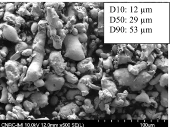
304-type and 316-type stainless steel-based feedstock materials were selected for low cost and compatibility. The feedstock wire and powder used to produce the coatings were both procured from Praxair (Danbury, CT, USA) and are listed in Table 1. The typical morphology and size of the feedstock powder are presented in Fig. 1.
Figure 1: Fe-101 powder morphology and size
1.2. Thermal Spray
Substrates were grit blasted with 24-grit alumina (Al2O3) prior to the arc-sprayed coating trials; degreasing was the only surface preparation used for cold-sprayed coating trials. Table 2 presents the spraying conditions used for this study. Arc spraying was performed using two systems: (1) An Oerlikon-Metco (Pfaffikon,
Switzerland) SmartArc (SA) system; and (2) A Miller (M) (now part of Praxair-TAFA) system. Arc spray current, atomizing gas pressure and spraying distance were adjusted to maximize coating adhesion. 5 samples were created, each having a coated layer approximately 500m in thickness. Cold-sprayed was performed using Kinetiks 4000 system from CGT GmbH (now part of Oerlikon-Metco). Cold-sprayed conditions were adjusted to maximize particle velocity while preventing gun clogging. 5 samples were created, each having a coated layer approximately 500 m on each sample. For this study, all of these samples were designated as “Single-Layer” samples.
In the course of the study, preliminary results regarding the performance of the “single layer” coated samples indicated that it would be desirable to produce a coating with the adhesion and thermal cycling resistance of cold-sprayed coatings as well as the wear performance of arc sprayed coatings. As a consequence, the concept of a hybrid, or duplex, coating with a cold-sprayed bond coat and an arc-sprayed top coat (either SA or M) was
D10: 12 µm D50: 29 µm D90: 53 µm
developed [16]. The cold-sprayed bond coat was sprayed directly on the Al substrate (that had not undergone grit blasting) using the standard spraying conditions; a thickness of about 300 µm was present. An arc-sprayed layer of about 500 µm was then added to the as-sprayed cold-sprayed layer; in this case, the as-cold sprayed surface was not grit blasted prior to the arc-spraying. For this study, all of these samples were designated as “Duplex” samples.
1.3. Characterization
Cross-sections through the coatings and substrates were first vacuum-mounted in an epoxy resin, then ground and polished using standard metallographic preparation procedures. A Hitachi (Tokyo, Japan) S-4700 field-emission scanning electron microscope was used in backscattered electron imaging (BSEI) mode to image the features seen in the coating cross-sections. For each coating, the BSEI mode was also used to capture 10 images at a magnification of 500X that were further analysis using Visilog software (St-Aubin, France) to measure the through-thickness coating, cross-sectional porosity, and, when applicable, oxide content. Finally, the S-4700 was used in the secondary imaging (SEI) modes to characterize the powder morphology.
Following microscopic examination, Vickers microhardness measurements were performed on the coatings on the polished cross-sections using a Buehler Micromet II Tester (Lake Bluff, IL, USA). Tests were conducted under 300 gf loads with a 15 second penetration time; at least 10 indentations per specimen were taken. Coating adhesion strength tests were performed according to the ASTM C-633-01 on the 1” diameter samples; for each coating, 3 samples were tested.
1.4. Wear Testing
A Falex (Sugar Grove, IL, USA) multi-specimen wear test rig was used to evaluate the wear performance of the deposited coatings using a pin-on-disk contact configuration. Test pins were created by sectioning material from a current brake rotor pad. The apparent contact area dimensions of the pins were 5 mm x 5 mm, and the length of the pin was approximately 13 mm. The sectioning of the brake pads was done in a manner that the pin
wear surface was parallel with the original brake pad surface. The coated test disks had a diameter of 86.36 mm and thickness of 10.16 mm (3.4” dia. x 0.4”). The following testing protocol was used: speed, load (apparent contact pressure), total sliding distance, and wear track diameter were 1 m/s, 4 MPa, 48,000 m and 63.5 mm (2.5”), respectively.
The wear rate of the test disks was expressed in volume loss per sliding distance (mm3/m) and was obtained through weight loss measurement and estimated material density. During the sliding test, coefficient of friction (COF) was measured and recorded using Labview (National Instrument, Austin, TX, USA).
1.5. Thermal Cycling
The effect of thermal cycling on the coating was assessed using a NRC custom laser rig [12]. Coated samples were successively heated by a 2 kW CW YAG laser and cooled down by compressed air, with a duration of 4 seconds for each step. A pyrometer and an infrared camera recorded the temperature of the sample being heated. A laser power of 1300W was selected to attain a heating rate of about 50-55°C/s. Once steady state was reached, cycles with maximum and minimum sample temperatures of approximately 470°C and 250°C,
respectively, were obtained. Once partial delamination of the coating occurred, a gap of low thermal
conductivity between the coating and the substrate arose. This gap generated hot spots on the coating in the heating zone upon cycling. The presence of hot spots equaling 25% of the sample surface area was chosen as the spalling criteria and the number of thermal cycles needed to reach this level recorded for each sample.
1.6. Corrosion Testing
During their service life, automobile brake disks are subjected to a variety of environmental conditions
involving temperature, humidity, and the presence of electrolytes typically formed by deicing salts. In order to simulate the effect of these corrosive conditions, a laboratory cyclic corrosion test based upon ISO 14993 was
used to perform a comparative corrosion resistance evaluation of the coated Al disks. Each single (1) cycle of the cyclic corrosion procedure is defined as follows:
Step 1. Salt-spray with 5% NaCl at 343C (100%RH) (for 3 hours) Step 2. Drying at 596C and 277%RH (for 5 hours)
Step 3. Wetting at 487C and > 95%RH (for 4 hours)
Each of the samples was inspected after each single cycle. The test was stopped when coating failure occurred or after completion of 120 cycles.
1.7. Dynamometer Trials
In order to evaluate the best performing coating, two samples of the duplex coatings were prepared and sent to the Ford Research and Innovation Center (Dearborn, MI, USA). These samples were tested on a LINK
(Plymouth, MI, USA) Scale Sample Brake Dynamometer and were compared with cast iron data. The Sub-Scale Dynamometer is designed to evaluate brake pad materials by using a 90 mm (3.54”) diameter disk using the same energy per unit area as a full-sized automobile rotor. It provides the ability to rapidly screen and comparatively evaluate materials without the need to use full-sized brake rotors.
In each test, two 30 mm by 15 mm (1.18” x 0.59”) rectangles are created from production brake pads and are aligned on the opposite sides of the same face of a rotor disk. The pads are pressed against the disk repeatedly to stop the sample disc as directed by a testing script. The dynamometer measures the applied force of the pads against the sample disc, the torque on the pad fixture, and the speed of the disc. From this data, the friction coefficient (also referred to as the “Effectiveness”) can be calculated
For this study, the 90 mm disks were produced from plates of cast Al 356-T6. The sections of the 90 mm disk in contact with the pads was thermally sprayed and subsequently machined to the prescribed flatness. A thermocouple was mounted 0.5mm below the surface to monitor the temperature. A similar disk, created from G3000 gray cast iron, was prepared to the same dimensions; this disk was used as a baseline to understand the effect of the duplex coating on the wear of the disks.
Two testing scripts were used on each individual sample. These tests are designed to test the extreme situations of brake use, and can yield results that are quite different from those seen in actual use. First, the Friction Test was performed. This test is designed to test the friction characteristics of the pad/sample combination at a variety of speeds, temperatures, and deceleration rates. Then, the second script, the Thermal Shock Test, was performed. This test was written specifically to test the adhesion of coatings. The disc is run up to the
maximum speed of 235 kph (145 mph) and then a hard stop is performed at 4.9 m/s/s (16 ft/s/s) by pressing the pads against the rotor. This is done a total of 5 times. This frictionally heats the sample up to near 500°C, at which time the sample is sprayed with water and allowed to cool. The rotor was then reburnished by stopping 50 times from 64.4 kph to 3.2 kph at 3.1 m/s/s (40 mph to 2 mph at 10 ft/s/s) to redevelop a transfer layer. This cycle of maximum speed, 5 stops, water spraying, and reburnishing was repeated sixteen times to complete the overall Thermal Shock Test.
Following completion of the individual tests, the changes in thickness of the disc and pads were measured to determine the amount of wear. For the discs, the thickness of four areas approximately 90 degrees apart was measured using a digital dial gauge. For the pads, the thickness of the pad material above the mounting plate was measured at the four corners of each rectangular pad. Again, the digital dial gauge was used to make the measurements.
2. Results and Discussion
Figure 2 presents the microstructures observed in the “single layer” arc-sprayed and cold-sprayed samples. Table 2 presents the adhesion, microhardness, porosity, and oxide levels obtained for these three types of coatings. As expected, the two arc-sprayed coatings exhibit high levels of oxide (20% and 43%) and a
significant amount of porosity (2 -3 area %.) Further, as Table 2 details, adhesion in the arc-sprayed coatings (for a coating thickness of about 500 µm) was about 30MPa. This is typical for arc-sprayed coatings where adhesion is provided through mechanical interlocking of the splats [3].
In contrast, Figure 2 and Table 2 show that the cold-sprayed coating has a microstructure nearly free from oxides. The level of porosity can be seen to vary through the thickness of the coating. The porosity was very low in the regions closest to the Al-substrate interface. The level of porosity did tend to increase in amount as the distance from the interface increases (Figure 2d); the highest level of porosity was observed adjacent to the cold spray coating surface. The lower level of porosity toward the interface is due to the peening effect inherent in cold spray-deposited powders. [17]. The adhesion strength exceeded the test glue adhesion value of 76 MPa for cold spray samples. This is consistent with values obtained in previously published studies for samples cold-sprayed under similar spraying conditions [13]. This high adhesion strength is partly attributed to the ability of the cold-sprayed steel particles to penetrate into the relatively soft Al substrate [13]. This can be seen in Figure 2c, where the interface between the A356 substrate and the Fe-based coating is shown. Prior to cold-spraying, the interface was flat, as there had been no grit blasting performed. As this figure shows, the interface is irregular as the cold-sprayed Fe-based particles have embedded themselves into the substrate. In addition, other mechanisms, such as adiabatic shear instability, may also have contributed to the bonding [14].
The hardness values of all three coatings are relatively similar, at about 300HV, and are twice the values typically reported for their bulk 300-seies stainless steel counterpart. The hardness values of the arc-sprayed coatings are attributed to the presence of the hard oxide phases and/or solute atoms [15]. In the case of the
cold-sprayed coating, cold working associated with the plastic deformation of the powder particles is most probably the source of the high coating hardness [14].
(a) (b) CS coating A356 0910076 09111010
(c)
(d)
Figure 2: Typical Coating Microstructures Observed in the (a) SA-coated sample (b) M-coated sample (c) CS-coated sample at the interface (d) CS-coated sample showing the coating through its thickness
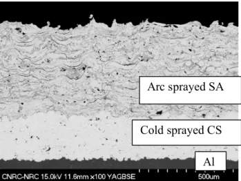
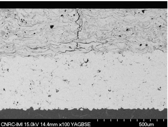
The microstructure of the Duplex SA coating is shown in Fig. 3. In general, examining the photo reveals that the features in the arc-sprayed portions are consistent with those seen in the single layer (large amount of oxides and porosity present). In addition, a comparison of Figure 3 with Figure 2d shows that the level of porosity present in the cold spray layer is similar to that seen adjacent to the exterior surface of the “single layer” cold-sprayed coating. 121205A1
Figure 3: Duplex SA coating microstructure
2.2. Wear Test Results
Table 4 presents the wear rates of the different thermal spray coatings as well as comparing them to the study benchmarks, grey cast iron and bulk 304 stainless steel. As this table illustrates, the arc-sprayed samples have wear rates similar to those of grey cast iron and much lower than bulk SS304. Similar results are seen when the COF of the arc-sprayed coatings is compared to grey cast iron. The good wear resistance of arc-sprayed
coatings is related to the composite microstructure. This microstructure is composed of an Fe-based metal matrix and oxide layers on each individual splat.
It has been widely observed that compacted/compressed third-body layers, or tribolayers, with a steady state thickness of 0.5 – 10 um (depending on type of vehicle, applied conditions, and composition of the starting friction materials), are formed on brake rotor surfaces [18]. Such tribolayers can effectively protect the friction material from abrasion as well as reduce rotor wear [8]. Several tribological studies [19,20] examined dry sliding wear. They found that finer wear debris particles are more easily agglomerated and become
consolidated by compressive load within the contacting area. This promotes the development load-bearing compacted layers that can reduce the degree of wear. On the other hand, larger wear debris particles were difficult to agglomerate and were more easily removed from the wear surface, causing permanent wear loss. In
Arc sprayed SA
Cold sprayed CS Al
this study, it is hypothesized that, in the arc-sprayed coatings, the oxide layers on the surface of splats limits the maximum wear debris particle sizes. This, in turn, leads to the formation of a larger amount of fine wear debris. As a result, stable wear-protective compact layers are more easily formed on the wear disk surface, leading to transition of wear mode from severe wear to mild wear. In addition, the oxides are harder than the stainless steel matrix, further improving the wear protectiveness of the tribolayers.
The wear rate of the cold-sprayed coating, altough better than bulk SS304, was significantly higher than that of the arc-sprayed samples. The wear improvement over the bulk material is attributed to the higher hardness of the cold-sprayed coating.
Wear tests performed on the Duplex SA coating (Table 4) confirmed that wear behavior equivalent to arc-sprayed coatings was obtained. This was the expected result, as the test only interacted with the arc-arc-sprayed top coat. As a consequence, it was not found relevant to extend the test matrix to Duplex M coating.
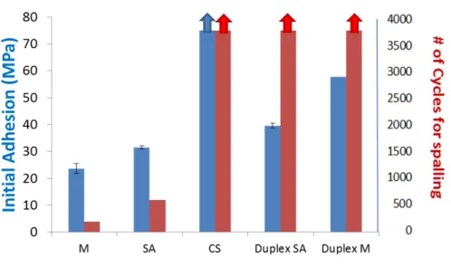
2.3. Adhesion Strength and Thermal Cycling Results
Figure 4 presents the results from the adhesion strength tests as well as the number of thermal cycles prior to spalling for several coatings. As this figure details, the “single layer” arc-sprayed coatings displayed the lowest resistance to spalling under thermal cycling; this is most probably due to their lower initial adhesion strength.
Cold-sprayed coatings were observed to have the highest resistance to thermal cycling, withstanding over 10,000 cycles without spalling. In addition to the beneficial effect of the excellent adhesion observed in the sprayed coatings, several other factors might contribute to this excellent performance. Even though cold-sprayed coatings are relatively brittle in the as-cold-sprayed state due to work hardening and possibly limited splat cohesion, the temperature reached by the coatings during thermal cycling tests might be high enough to lead to a “in-situ” coating annealing during the first series of thermal cycles. The coating ductility would therefore
improve with the number of cycles, leading to much higher coating toughness compared to the arc-sprayed coatings (which contain high levels of defects and a brittle oxide phase.) As a consequence, the cold-sprayed coatings would be able to accommodate larger thermal stresses without cracking. From results of Phuong et al. [21], a temperature of approximately 500°C would be the onset of the annealing temperature for cold-sprayed stainless steels when using a conventional furnace-based heat treatment. Further work would be required to validate this hypothesis for the laser heating system used in this study.
Finally, the thermal cycling coating performance might also be affected by differences in the heat transfer. Laser flash testing determined that the thermal diffusivity for the cold-sprayed coating was more than twice that of the arc-sprayed coatings (1.2 x 10⁻⁶m2/s vs 2.8 x 10⁻⁶ m2/s). More rapid heat dissipation in the cold-sprayed coating could lead to reduced thermal stresses compared to the arc-sprayed coatings for the same thermal cycling conditions.
Figure 4 also shows that the adhesion strength of both Duplex coatings was found to be above the as-sprayed coatings but lower than the cold-sprayed coatings. This is a result of the delamination between the arc-sprayed layer and the cold-sprayed layer. It should be noted that this failure occurred prior to any delamination of the cold-sprayed layer from the substrate. In spite of the lower adhesion strength, the resistance of the duplex coatings to thermal cycling was found to be comparable to the “single layer” cold-sprayed coating. As Figure 4 details, the Duplex coatings both survived 10,000 cycles without spalling. It is hypothesized that the cold-sprayed bond coat might act as a transition layer. This will reduce the thermal stresses induced in the arc-sprayed layer, improving the overall performance of the duplex coating.
2.4. Corrosion Results
The different types of coatings also underwent a corrosion evaluation using the test detailed in section 1.6. Figure 5 shows photographs of selected samples after accelerated cyclic corrosion tests. Figure 5a and 5b show that both arc-sprayed coatings exhibit general corrosion similar to that observed in carbon steels. The thin chromium oxide layer, usually responsible for the passivation of stainless steel, was not observed on the
deposited coatings. This is believed to be a consequence of the majority of the chromium being oxidized during the spray process [22]. In addition, saline -containing moisture also penetrated through the porous arc-sprayed coatings and caused corrosion at the Al/steel interface. This galvanic coupling created Al corrosion products which, in turn, generated blisters at the interface. In these cases, coating debonding was observed after 17 cycles in the SA- samples and after 24 cycles in the M samples. The galvanic corrosion of Al was observed to be present only in a region close to the stainless steel-aluminum interface. Thus, the “bulk” Al substrate was less affected than the Al at the SS-Al interface. In both samples, the stainless steel coating was not affected by galvanic corrosion.
(a)
(b)
(c)
M-17
CS-120
Al-SS interfacial region on the side of the sample.
(d)
Duplex SA-120
(e)
Figure 5: Samples after accelerated cyclic corrosion (a) SA (b) M (c) CS (d) duplex SA (e) duplex M.
In contrast, the cold-sprayed coating (Fig. 5(c)) was highly corrosion resistant. It went through a complete test duration of 120 corrosion cycles without debonding. The absence of oxidation within the coating appears highly beneficial as the chromium remained available for corrosion protection. In addition, the dense nature of the coating prevented the infiltration of the saline-rich solution into the coating layer; thus, no blistering was observed. However, the Al substrate disks were strongly corroded, with pitting being observed at the Al-SS interfacial region; this is again believed to be due to the galvanic coupling between SS and Al. These results, taken in conjunction with those for the arc-sprayed coatings, indicate that galvanic corrosion should be further investigated. This investigation would need to determine how critical galvanic corrosion is for the targeted application and if low-cost, easily implementable mitigation measures (such as sealants and/or revised designs of coating/Al interfaces) can be developed.
Duplex coatings were also examined and found to be resistant to corrosion. As Figures 5d and 5e illustrate, there was no coating debonding observed after completing the 120 test cycles. As these figures show, a few small blisters were observed, as well as limited general corrosion. This indicates that the cold-sprayed bond coat is efficient in acting as a barrier to the infiltration of the saline humidity. Further coating investigations have shown area of substrate porosity can create a discontinuity in the bond coat, as shown in Fig. 5(e). Although a direct link could not be confirmed in this study, it is believed that the few blisters observed on the duplex coatings could origin from such discontinuity.
2.5. Dynamometer Trials
The two Duplex SA coated samples that underwent the Friction and Thermal Shock Tests did not delaminate or fail catastrophically, indicating the strong adhesion of the coating to the substrate. Figure 6 presents a
representative example of the measured friction coefficient through the four hundred braking events of the Friction Test.
Overall, the coefficients of friction measured from the Duplex SA samples during dynamometer trials (µ 0.31 are lower than those measured during the pin-on-disk wear test experiments (µ 0.42). This difference can be attributed to the differences in the test rig configurations as well as the changing nature of the contacting materials. First, the friction and wear behavior of materials, including brakes and brake linings, are geometry-dependent. For example, differences in test specimen geometries and test rig configurations can affect the probabilities of wear debris being trapped in the rubbing interface. This will affect the formation and subsequent properties of the tribolayers on contact surfaces. This, in turn, will lead to different wear and friction behaviors in the different testing systems using the same tribo-pairs. Second, new (green) phenolic-based brake pad materials finish their curing in-situ under the influence of braking pressures and temperatures. It is thus expected that the actual properties of the braking pad specimens during the tests will continuously change and be different. Thus, the behavior between the lab wear (POD) and the dynamometer tests will be different because contact conditions and thermal history differ significantly in these two systems. The apparent changes in braking effectiveness after about 200 stops in Figure 6 might be related to the property evolution of the braking pad materials with braking stops.
Figure 6: Average Effectiveness (Coefficient of Friction) During A Friction Test of Coating #23 (in green) and Cast Iron (in blue).
The dynamometer trials also allowed the wear rate of both the coating and the pad material during braking conditions to be evaluated. As Table 5 shows, the disc thickness increased on both of the Duplex SA samples from the Friction tests. This increase is a typical result that was seen on the cast iron comparator sample (Table 5) as well as in multiple other tests conducted on the Sub-Scale Dynamometer. The increase is most probably due to the creation and growth of the transfer layer that builds up on the disc during mild braking. In contrast, the samples from the Thermal Shock Test showed a decrease in disc thickness. This is most likely a
consequence of the hard braking used to build up the high temperatures for the Thermal Shock Test, which removed any transfer layer that had built up. Overall, when comparing samples 22 and 23 with cast iron, it appears the Duplex SA-coated samples produced a thicker transfer layer than that produced by the cast iron. Pad wear rates were about doubled with the coated samples, which are still considered in an acceptable range.
Cast Iron
#23 (Duplex
The worn surfaces of the Duplex SA samples were characterized after the dynamometer trials. Fine cracks were observed on the surface of the coating (Figure 7); subsequent SEM examination found that the cracks stopped at the arc-sprayed/cold-sprayed interface (Figure 8). A cross-sectional sample was extracted and used for
adhesion testing. The adhesion of the post-tested Duplex coating was found to be 36 MPa, which was close to the 40 MPa initial coating adhesion (Table 3).
Figure 8: Microstructure of a Duplex SA-Coated Sample after Dynamometer Testing (#22). Cracks were generated at the surface of the coating and propagated in the arc spray layer upon cycling.
2.6. Rotor Mass Comparison
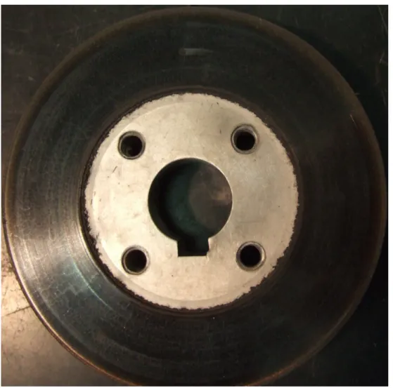
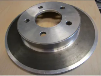
To understand the mass reduction potential of applying a thermal spray coating to a lightweight disc brake rotor, a comparator with a current cast iron brake rotors was created. This was done by obtaining a commercially-available cast iron rotor. Next, an Al 6061 plate was obtained and machined to the same dimensions as the commercially-available cast iron rotor. Duplex SA coating was applied onto the brake pad surface of the 6061 comparator (Fig. 9). The sprayed coating was then machined to a uniform thickness so that the overall thickness of the brake pad surface was consistent with that present in the commercially-available cast iron rotor.
Figure 9: The 6061 Mass Comparator Disk (Coating is the dark phase present.)
The two rotors were then compared on the basis of mass. Compared to the commercially-available cast iron rotor, the overall weight of the 6061 comparator disk was decreased from 4.28 to 1.77 kg. This weight
reduction of nearly 60% represents a maximum possible value. In practice, the weight reduction for a specific component would probably be less. In general, the difference in mechanical properties between cast iron and aluminum (especially the modulus) might require that the design be adjusted to ensure performance and durability.
3. Conclusions
This paper summarizes the results of a study examining the potential of using thermal spray to create a stainless steel-coated aluminum-based brake rotor for possible future application in cars and light trucks. Both arc- and cold-sprayed deposition methods were investigated as coating processes.
This study found that arc-sprayed 300-series stainless steel coatings exhibited promising wear behavior: they displayed equivalent wear rates compared with the baseline gray cast iron disks with similar coefficients of friction. This was attributed to the composite microstructure composed of a metallic matrix as well as oxide layers on the splats formed during coating deposition. However, arc- sprayed coatings on top of an aluminum
substrate possess relatively low adhesion strength. This is a key issue as adhesion strength is essential both for the buildup of thick coatings and to sustain the stresses caused by thermo-mechanical cycling. Arc-sprayed coatings were also found to be sensitive to corrosion. The presence of porosity in the arc-sprayed coatings allowed penetration of saline-based moisture. This, in turn, generated corrosion products at the interface between the stainless steel coating and the aluminum substrate that caused blistering in the coating and interfacial debonding. Furthermore, chromium depletion of the metal matrix, caused by the arc-spraying process, allowed subsequent general corrosion to arise on the exterior of the stainless steel-coated surface.
This study also found that cold sprayed coatings present high bond strength and thermal cycling resistance. Due to their high density, adhesion, and the absence of in-flight oxidation during deposition, the cold sprayed
coatings also exhibited high resistance to general corrosion, surface blistering, and interfacial debonding during salt spray tests. However, cold sprayed coatings exhibited poorer wear resistance compared to the standard grey cast iron currently used in commercial applications. The coefficient of friction of the cold-sprayed coating was observed to be similar to that of a commercially-available gray iron.
Finally, duplex coatings made of a cold-sprayed bond coat and an arc-sprayed top coat were investigated. The cold-sprayed bond coat was found to significantly improve the coating adhesion strength and resistance to thermal cycling). In addition, it also provided enhanced protection against corrosion by inhibiting blistering and debonding. The arc-sprayed top coat offered wear resistance similar to the coatings that were formed as a single layer using arc spraying. Sub-scale dynamometer tests were conducted on a limited set of Duplex-coated samples. The results of these tests found that the Duplex-coated samples had somewhat higher, but not
unreasonable wear rates compared to the cast gray iron comparator sample. However, it should be remembered that these tests are designed to test the extreme situations of brake use, and are indicative only; real world use could yield results that are quite different In conclusion, the results from this study show that stainless steel coatings on aluminum substrates could be viable substitute for the cast iron in future brake rotors.
4. Acknowledgments
The authors would also like to acknowledge the technical assistance of F. Belval, B. Harvey, J.Sykes, J.F. Alarie, D.de Lagrave, M. Thibodeau, K. Théberge and M. Lamontagne.
5. References
[1] R. Heuss, N. Müller, W.Sintern, A. Starke and A. Tschiesner, Lightweight, Heavy Impact, report from McKinsey & Company, February 2012
[2] K. Martinsen, S.J. Hu and B.E. Carlson, Joining of Dissimilar Materials, CIRP Annals – Manuf. Technol., 2015, 64, p 679-699
[3] O.O. Popoola, M.J. Zaluzec and R.C. McCune, Novel Powertrain Applications of Thermal Spray Coatings,
Surf. Eng., 1998, 14 (2), p 107-112
[4] K. Bobzin, F. Ernst, J. Zwick, T. Schlaefer, D. Cook, K. Nassenstein, A. Schwenk, F. Schreiber, T. Wenz, G. Flores and M. Hahn, Coating Bores of Light Metal Engine Blocks with a Nanocomposite Material using the Plasma Transferred Wire Arc Thermal Spray Process, J. Therm. Spray Technol., 2008, 17(3), p 344-351 [5] E. Lugscheider, R. Dicks, K. Kowalsky, D. Cook, K. Nassenstein and C. Verpoort, A Materials System and
Method of its Application for the Wear Protection of Aluminium Engine Cylinder Bore Surfaces, Thermal
Spray 2004: Advances in Technology and Application, ASM International, May 10-12, 2004 (Osaka,Japan),
ASM International, 2004, p 334-340
[6] R.K. Uyyuru, M.K. Surappa and S. Brusethaug, Effect of Reinforcement Volume Fraction and Size Distribution on the Tribological Behavior of Al-Composite/ Brake Pad Tribo-Couple, Wear, 2006, 260, p1248–1255
[7] Ratnesh Dwivedi (Lanxide Corp), “Performance of MMC Rotors in Dynamometer Testing”, SAE Paper #940848, March 1994.
[8] A. Daoud and M.T. Abou El-khair, Wear and Friction Behavior of Sand Cast Brake Rotor Made of A359-20vol% SiC Particle Composites Sliding Against Automobile Friction Material, Tribol. Int., 2010, 43,p 544-553
[9] N. Natarajan, S. Vijayarangan and I. Rajendran, Wear Behavior of A356/25SiCp Aluminum Matrix Composites Sliding Against Automobile Friction Material, Wear, 2006, 261, p 812–822
[10] M. Macnaughta, Cast Iron Brake Discs—A Brief History of their Development and Metallurgy, Technical Report, Foundryman, 1998, p 321-324.
[11] K.M. Shorowordi, Haseeb, ASMA and J.P. Celis, Velocity Effects on the Wear, Friction and Tribochemistry of Aluminum MMC Sliding Against Phenolic Brake Pad, Wear, 2004, 256, p1176–81 [12] D. Poirier, J.M. Lamarre and J.G. Legoux, Thermal Cycling Assessment of Steel-Based Thermal Barrier
Coatings for Al Protection, J. Therm. Spray Technol., 2014, 24(1-2), p 175-184
[13] A. Sova, S. Grigoriev, A. Okunkova and I. Smurov, Cold spray deposition of 316L stainless steel coatings on aluminium surface with following laser post-treatment, Surf. Coat. Technol., 2013, 235, p 283-289
[14] P. King, M. Yandouzi and B. Jodoin, The Physics of Cold Spray, Modern cold spray; Materials,
Process and Application, J. Villafuerte, Springer, 2015, p 44-67
[15] S. Dallaire, J.G. Legoux, H. Levert, Abrasion Wear Resistance of Arc-Sprayed Stainless Steel and Composite Stainless Steel Coatings, J. Therm. Spray Technol., 1995, 4(2), p 163-168
[16] D. Poirier, E. Irissou, J.G. Legoux and D. Gallant, Bi-Layer Iron Coating of Lightweight Metallic Substrate, US patent application US20170204920A1
[17] P. King, M. Yandouzi and B. Jodoin, The Physics of Cold Spray, Modern cold spray; Materials, Process
and Application, J. Villafuerte, Springer, 2015, p 107-147
[18] P.J Blau, Microstructure and detachment mechanism of friction layers on the surface of brake shoes, J.
[19] J. Jiang, F.H. Stott and M.M. Stack, The Role of Triboparticulates in Dry Sliding Wear, Tribol. Int., 1998, 31, p 245-256
[20] J. Jiang, F.H. Stott and M.M. Stack, A Mathematical Model for Sliding Wear of Metals at Elevated Temperatures,
Wear, 1995, 181-183, p 20-31
[21] P. Vo, E. Irissou, S. Kudapa and M. Nestler, Strength and Wear Properties of Stainless Steel Coatings Produced by Cold Spray with Various Powder Sizes, Thermal Spray 2013: Proceedings of the International Thermal spray Conference, Innovative Coating Solutions for the Global Economy, May 13-15, 2013 (Busan, Korea),
ASM International, 2013
[22] Z. Zeng, N. Sakoda and T. Tajiri, Corrosion Behavior of Wire-Arc-Sprayed Stainless Steel Coating on Mild Steel,
Figure Captions
Figure 1: Fe-101 powder morphology and size... 6
Figure 2: Coating microstructures (a) SA coating (b) M coating (c) Interface CS coating / Al 356... 13
Figure 3: Duplex coating microstructure... 14
Figure 4: Coating initial adhesion and number of thermal cycles prior to spalling... 16
Figure 5: Samples after accelerated cyclic corrosion (a) SA (b) M (c) CS (d) duplex SA (e) duplex M... 20
Figure 6: Picture of the prototype disk (coating is darker than the Al disk). ... Error! Bookmark not defined. Figure 7: Average effectiveness during Friction Tests of coating #23 (in green) and cast iron (in blue)... 22
Figure 8: Coated sample #21 after dynamometer testing ... 23
Figure 9: Microstructure of coated sample #21 after dynamometer testing. Cracks were generated at the surface of the coating and propagated in the arc spray layer upon cycling... 24
Tables
Table 1: Feedstock Materials Used In This Study
Feedstock Commercial Name Composition
Wire 80T
SS304-type; 18Cr, 8Ni, 1.5Mn, 0.5Si, 0.12C, Fe bal.
Powder FE-101 SS316-type; 17Cr, 12Ni, 2.5Mo, Fe bal.
Table 2: Spraying Conditions
Coating ID Equipment Feedstock Material Current or
Gas Temperature Gas P ressure (MPa) S tand -O ff Distanc e(cm)
SA Smart Arc 80T 100A 0.4 15
M Miller 80T 100A 0.4 10
CS CGT FE-101 700°C 4 8
Table 3: Selected Coatings And Their Properties
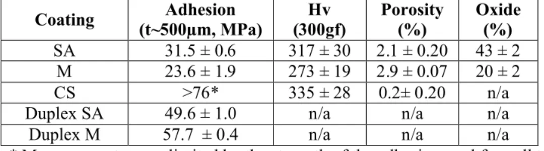
Coating (t~500µm, MPa)Adhesion (300gf)Hv Porosity (%) Oxide(%)
SA 31.5 ± 0.6 317 ± 30 2.1 ± 0.20 43 ± 2 M 23.6 ± 1.9 273 ± 19 2.9 ± 0.07 20 ± 2 CS >76* 335 ± 28 0.2± 0.20 n/a
Duplex SA 49.6 ± 1.0 n/a n/a n/a
Duplex M 57.7 ± 0.4 n/a n/a n/a
Table 4: The Effect of Coating Type On The Wear Rate And Coefficient Of Friction (COF)
Coating
Material Spray Method
Wear rate
(10-5mm3/m) COF
Gray cast iron --- 1.294 ± 0.166 0.36 Bulk SS304 --- 45.303 ± 25.483 0.72
SA Arc 1.524 ± 0.672 0.36
M Arc 0.730 ± 0.270 0.35
CS Cold 4.774 ± 1.664 0.38
Duplex SA Cold + Arc 0.751 ± 0.067 0.42
Table 5: Samples Wear Under Dynamometer Trials
Sample Test Disc Wear (mm) Pad Wear (mm)
22 Friction Test 0.02921 -1.25095
Thermal Shock Test -0.0352425 -1.59893 23 Friction Test 0.0257175 -1.3611225
Thermal Shock Test -0.0288925 -1.0575925 Cast Iron Friction Test 0.0073025 -0.51435