Publisher’s version / Version de l'éditeur:
Vous avez des questions? Nous pouvons vous aider. Pour communiquer directement avec un auteur, consultez la première page de la revue dans laquelle son article a été publié afin de trouver ses coordonnées. Si vous n’arrivez pas à les repérer, communiquez avec nous à [email protected].
Questions? Contact the NRC Publications Archive team at
[email protected]. If you wish to email the authors directly, please see the first page of the publication for their contact information.
https://publications-cnrc.canada.ca/fra/droits
L’accès à ce site Web et l’utilisation de son contenu sont assujettis aux conditions présentées dans le site LISEZ CES CONDITIONS ATTENTIVEMENT AVANT D’UTILISER CE SITE WEB.
Internal Report (National Research Council of Canada. Institute for Research in Construction), 1987-06-01
READ THESE TERMS AND CONDITIONS CAREFULLY BEFORE USING THIS WEBSITE. https://nrc-publications.canada.ca/eng/copyright
NRC Publications Archive Record / Notice des Archives des publications du CNRC : https://nrc-publications.canada.ca/eng/view/object/?id=5aaad747-d24d-499f-8c27-74c19ce253fb https://publications-cnrc.canada.ca/fra/voir/objet/?id=5aaad747-d24d-499f-8c27-74c19ce253fb
NRC Publications Archive
Archives des publications du CNRC
For the publisher’s version, please access the DOI link below./ Pour consulter la version de l’éditeur, utilisez le lien DOI ci-dessous.
https://doi.org/10.4224/20338033
Access and use of this website and the material on it are subject to the Terms and Conditions set forth at
Modelling of Ice-Propeller Blade Impact Experiments
R427
Natlonal Research Consell natlonal
I*
Councll Canada de recherches Canada Institute for lnstitut deResearch in recherche en Construction construction
Modelling of ice-Propeller Blade Impact
Experiments
M.
SayedInternal Report No. 537 Date
of
issue: June 1987ANALYZED
NRC
-
CIS37 L I B R A R YThis is an internal report of the institute for Research in Construction. Although not intended for general distribution, it may be cited as a reference in other publications.
MODELLING OF ICE-PROPELLER BLADE IMPACT EXPERIMENTS M. Sayed G e o t e c h n i c a l S e c t i o n I n s t i t u t e f o r Research i n C o n s t r u c t i o n BACKGROUND T h i s r e p o r t b r i e f l y d e s c r i b e s a numerical s i m u l a t i o n o f l a b o r a t o r y e x p e r i m e n t s r e l a t e d t o i c e - p r o p e l l e r b l a d e impact. The a n a l y s i s i s based on t h e approach developed by V a r s t a (1983) t o model i c e impact problems. The f i n i t e element method i s used t o c a l c u l a t e l i n e a r e l a s t i c , t h r e e d i m e n s i o n a l s t r e s s e s i n i c e . Loads a r e determined by i n c o r p o r a t i n g an a n i s o t r o p i c
f a i l u r e c r i t e r i o n .
The experiments, performed e a r l i e r by J u s s i l a (1987), i n c l u d e d measurements o f f o r c e s on r i g i d sharp i n d e n t o r s as t h e y impact b l o c k s o f
B a l t i c Sea i c e .
The p r e s e n t work was conducted a t t h e Technical Research Centre o f F i n l a n d (VTT) d u r i n g a v i s i t t h a t t o o k p l a c e i n January 1987. The v i s i t was a p a r t o f t h e J o i n t Research P r o j e c t Agreement No. 1 ( I c e Load P e n e t r a t i o n Model ) between Canada and F i n l a n d .
ANALYSIS
1. Model
-
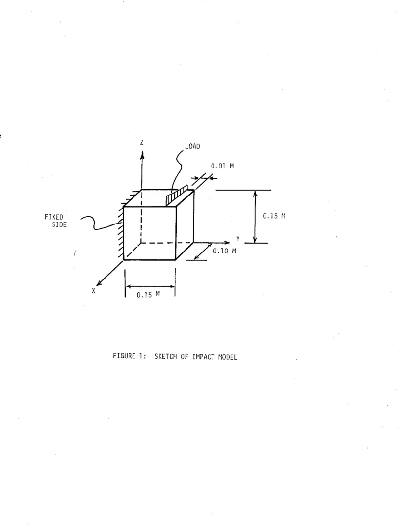
A prism, 0.15 x 0.15 x 0.1 m, as shown i n F i g u r e 1, i s assumed t o
r e p r e s e n t t h e i c e b l o c k . A l i n e l o a d a c t s a t a d i s t a n c e o f 0.01 m from, and p a r a l l e l t o , t h e f r e e s i d e o f t h e p r i s m . The i n d e n t o r was s l i g h t l y i n c l i n e d t o t h e h o r i z o n t a l when i m p a c t i n g t h e t o p s i d e o f t h e i c e d u r i n g t h e
e x p e r i m e n t s . Therefore, t h e l i n e l o a d may n o t be u n i f o r m (e.g. t r i a n g u l a r ) .
The i c e i s assumed t o be l i n e a r l y e l a s t i c u n t i l f a i l u r e i s i n i t i a t e d . T e s t e d samples were c o l u m n a r - g r a i n e d and t h u s may be t r a n s v e r s e l y i s o t r o p i c . S t r e s s c a l c u l a t i o n s , however, a r e c a r r i e d o u t u s i n g i s o t r o p i c e l a s t i c
p r o p e r t i e s . T h i s i s c o n s i d e r e d adequate f o r a p r e l i m i n a r y q u a l i t a t i v e i n s i g h t i n t o t h e problem. The v a l u e s o f Young's modulus E and P o i s s o n ' s r a t i o v a r e chosen as:
F a i l u r e i s assumed t o be governed by t h e Tsai-Wu c r i t e r i o n . F o r t r a n s v e r s e l y i s o t r o p i c i c e , w i t h t h e l o n g axes of t h e columns p a r a l l e l t o t h e 3 - d i r e c t i o n , t h e f a i l u r e c r i t e r i o n i s w r i t t e n as
and
where 01, o 2 and u3 a r e t h e normal s t r e s s e s , and T12, T23 and
are
t h e shear s t r e s s e s . Tests on B a l t i c Sea i c e ( V a r s t a , 1983) r e s u l t e i n t h e f o l l o w i n g v a l u e s o f t h e parametersThe f a i l u r e parameter A r e p r e s e n t s a measure o f t h e p r o x i m i t y o f t h e s t r e s s s t a t e t o t h e f a i l u r e envelope (A = 1 corresponds t o f a i l u r e ) . It i s g i v e n by
where AF c o n s i s t s o f t h e f i r s t two terms and
BG
c o n s i s t s o f t h e n e x t s i x terms i n e q u a t i o n ( 2 ) .2. C a l c u l a t i o n p r o c e d u r e s
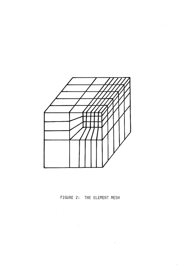
The f i n i t e element program ADINA i s used t o d e t e r m i n e t h e t h r e e d i m e n s i o n a l s t r e s s d i s t r i b u t i o n . The element mesh i s shown i n F i g u r e 2. S o l i d , 20 node elements a r e used. Loading cases a r e as f o l l o w s :
1. U n i f o r m l i n e l o a d = 1 kN 2. T r i a n g u l a r l i n e l o a d = 1 kN
3. Uniform l i n e d i s o l a c e m e n t = 0.5 x l o m 5 m
These f o r c e and d i s p l a c e m e n t v a l u e s a r e chosen t o be c l o s e t o f a i l u r e l o a d s p r e d i c t e d by a p r e l i m i n a r y t e s t run.
The r e s u l t i n g s t r e s s e s ( a t each e l e m e n t ' s i n t e g r a t i o n p o i n t s ) a r e used as i n p u t f o r a program t h a t c a l c u l a t e s t h e f a i l u r e parameter A . R e s u l t s a r e o b t a i n e d f o r two cases c o n s i d e r i n g i c e columns t o be p a r a l l e l , and
p e r p e n d i c u l a r t o t h e l i n e l o a d .
RESULTS
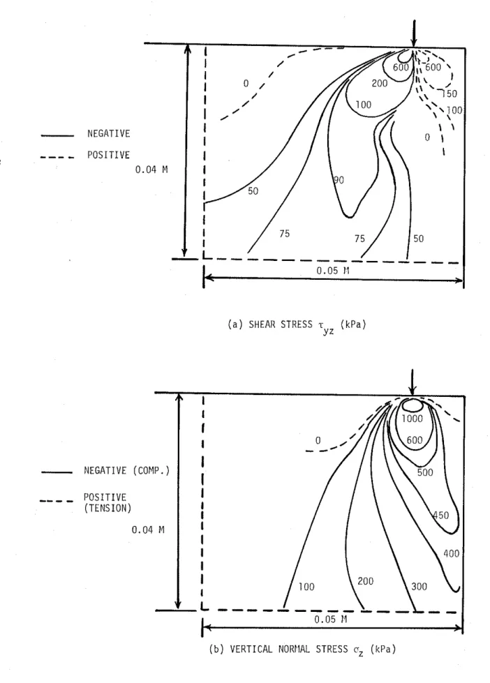
S t r e s s d i s t r i b u t i o n s c o r r e s p o n d i n g t o l o a d i n g case 1 a t a v e r t i c a l p l a n e near t h e c e n t r e o f t h e i c e b l o c k a r e shown i n F i g u r e 3. As mentioned e a r l i e r , t h e s e s t r e s s e s a r e c a l c u l a t e d u s i n g i s o t r o p i c e l a s t i c p r o p e r t i e s . These a r e t y p i c a l o f a l l l o a d i n g cases. Values o f t h e shear s t r e s s e s ,T, and T~~ a r e n o t shown because t h e y a r e t o o s m a l l .
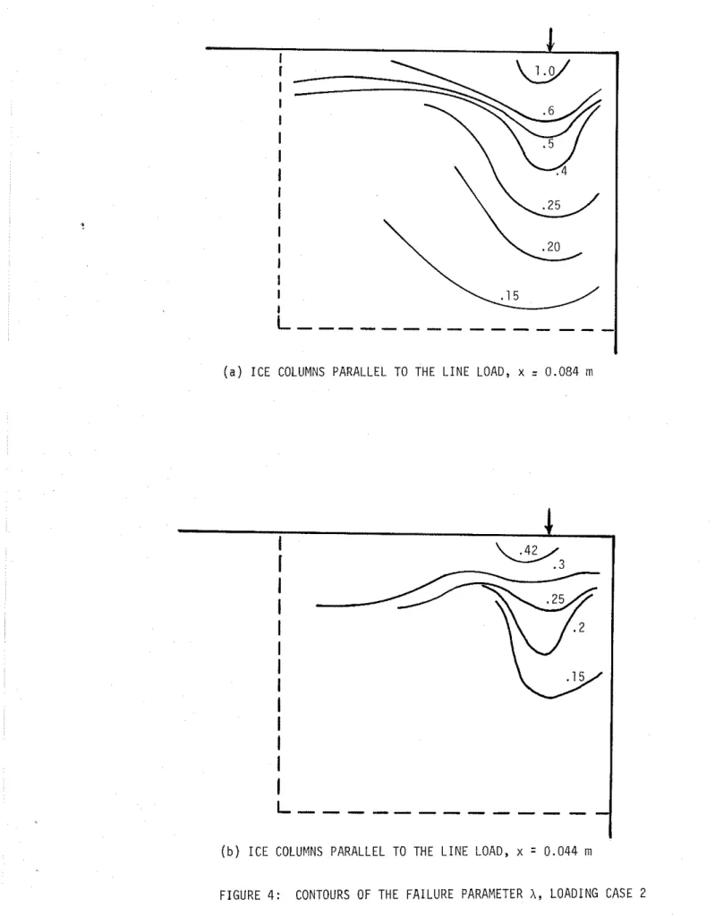
Contours o f t h e f a i l u r e parameter A ( i n a v e r t i c a l p l a n e near t h e
b l o c k ' s f r o n t ) f o r l o a d i n g case 2 and c o n s i d e r i n g i c e columns t o be p a r a l l e l t o t h e l o a d a r e shown i n F i g u r e 4a. The v a l u e o f A near t h e a p p l i e d l o a d
( a p p r o x i m a t e l y 1) i n d i c a t e s t h a t f a i l u r e i s i n i t i a t e d ; i .e. t h e l i m i t i n g l o a d i s equal t o t h e chosen v a l u e o f 1 kN. I f X was n o t equal t o 1, t h e n t h e l i m i t i n g l o a d would be equal t o t h e chosen v a l u e d i v i d e d by A .
The r e s u l t s a t a v e r t i c a l p l a n e near t h e c e n t r e o f t h e b l o c k a r e shown i n F i g u r e 4b; t h o s e a t a p l a n e near t h e edge, b u t c o n s i d e r i n g i c e columns t o be p e r p e n d i c u l a r t o t h e l i n e load, a r e shown i n F i g u r e 4c.
According t o F i g u r e 4a, f a i l u r e i n i c e w i t h columns p a r a l l e l t o t h e l i n e l o a d i s l i k e l y t o p r o g r e s s a l o n g a v e r t i c a l plane. I n s p e c t i o n o f t h e c o r r e s p o n d i n g s t r e s s d i s t r i b u t i o n r e v e a l s t h a t f a i l u r e i s p r i m a r i l y caused by t h e v e r t i c a l compressive normal s t r e s s . I f i c e columns a r e p e r p e n d i c u l a r t o t h e l o a d ( F i g u r e 4c), f a i l u r e would p r o g r e s s a l o n g a p l a n e i n c l i n e d a p p r o x i m a t e l y 30 degrees t o t h e v e r t i c a l , and would be caused by shear s t r e s s e s .
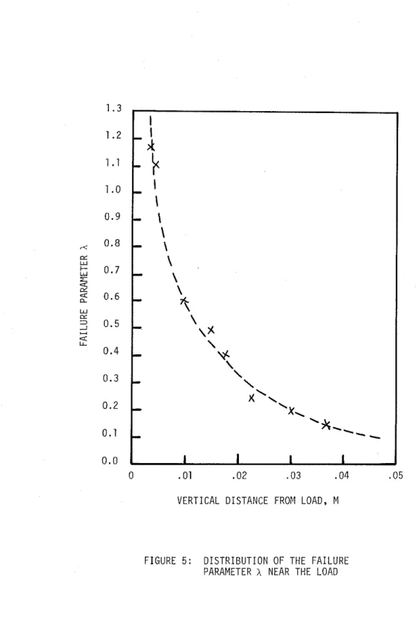
Both F i g u r e s 4a and 4c show t h a t X = 1 near t h e c o n c e n t r a t e d l o a d . Accuracy a t t h i s r e g i o n , however, i s l i m i t e d because o f t h e f i n i t e element d i s c r e t i z a t i o n . The parameter A ( f r o m F i g u r e 4a) i s p l o t t e d versus t h e v e r t i c a l d i s t a n c e from t h e l o a d i n F i g u r e 5 t o i l l u s t r a t e i t s s p a t i a l r a t e o f change. More t e s t runs a r e s t i l l needed t o examine mesh s i z e e f f e c t s .
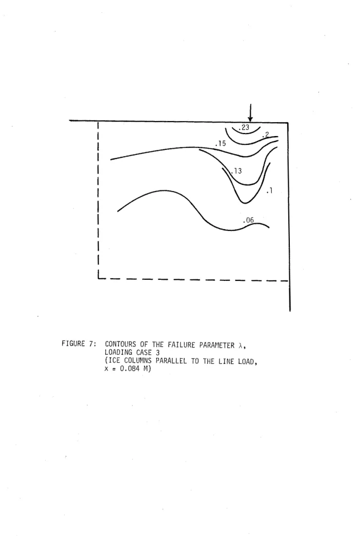
R e s u l t s from l o a d i n g cases 1 ( u n i f o r m l i n e l o a d ) , and 3 ( u n i f o r m l i n e d i s p l a c e m e n t ) a r e shown i n F i g u r e s 6 and
7
r e s p e c t i v e l y . They f o l l o w t r e n d s s i m i l a r t o t h o s e o f l o a d i n g c a s e 2.CONCLUDING REMARKS
I n i t i a l r e s u l t s from an a n a l y t i c a l model o f i c e - p r o p e l l e r b l a d e
e x p e r i m e n t s were presented. Load p r e d i c t i o n s appear t o be reasonable. The s t u d y i n d i c a t e s t h a t t h e m o d e l l i n g approach developed by V a r s t a (1983) can be used t o t r e a t cases o f i c e i m p a c t w i t h sharp i n d e n t o r s .
ACKNOWLEDGEMENT
T h i s work was c a r r i e d o u t i n c o l l a b o r a t i o n w i t h c o l l e a g u e s f r o m VTT. Many c o n t r i b u t i o n s were made by K. Riska, P. K l i n g e and M. J u s s i l a , VTT, and by Dr. R. F r e d e r k i n g , NRCC. F i n a n c i a l s u p p o r t was p r o v i d e d by t h e Canadian Coast Guard.
REFERENCES
Varsta, P., 1983. On t h e mechanics o f i c e l o a d on s h i p s i n t h e B a l t i c Sea. Technical Research Centre o f F i n l a n d , P u b l i c a t i o n s 11.
F I X E D S I D E
NEGATIVE P O S I T I V E
( a ) SHEAR STRESS T ( k P a ) Y Z
( b ) VERTICAL NORElAL STRESS cZ ( k P a ) NEGATIVE (COMP. )
P O S I T I V E (TENSION)
0 . 0 4 M
FIGURE 3 : STRESS D I S T R I B U T I O N , LOADING CASE 1
( x
-
0 . 0 4 4 m ) AI
II
II
I
I
I I II
II
I
Iv
L
----
0 . 0 5 )INEGATIVE (COMPRESSION) P O S I T I V E (TENSION)
0.
( c ) HORIZONTAL NORMAL STRESS oy ( k P a )
NEGATIVE (COMPRESSION) P O S I T I V E (TENSION)
0 .
L
- - -
- - -
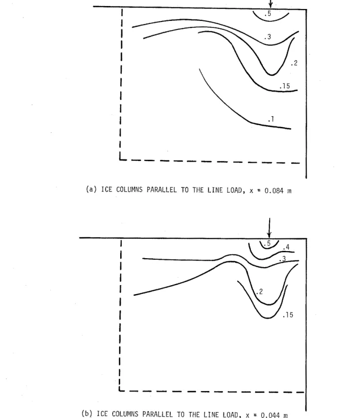
( a ) I C E COLUMNS PARALLEL TO THE L I N E LOAD, x = 0 . 0 8 4 m
( b ) I C E COLUMNS PARALLEL TO THE L I N E LOAD, x = 0 . 0 4 4 m
0 .01 . 0 2 . 0 3 . 0 4 . 0 5 VERTICAL DISTANCE FROM LOAD, M
FIGURE 5 : D I S T R I B U T I O N OF THE FAILURE PARAMETER X NEAR THE LOAD
( a ) I C E COLUMNS PARALLEL TO THE L I N E LOAD, x = 0 . 0 8 4 m
( b ) I C E COLUMNS PARALLEL TO THE L I N E LOAD, x = 0 . 0 4 4 n1
FIGURE 7: CONTOURS OF THE F A I L U R E PARAFIETER A,
LOADING CASE 3
( I C E COLUMNS PARALLEL TO THE L I N E LOAD,