Publisher’s version / Version de l'éditeur:
Journal of Thermal Insulation, 6, pp. 156-173, 1983-01
READ THESE TERMS AND CONDITIONS CAREFULLY BEFORE USING THIS WEBSITE. https://nrc-publications.canada.ca/eng/copyright
Vous avez des questions? Nous pouvons vous aider. Pour communiquer directement avec un auteur, consultez la première page de la revue dans laquelle son article a été publié afin de trouver ses coordonnées. Si vous n’arrivez pas à les repérer, communiquez avec nous à PublicationsArchive-ArchivesPublications@nrc-cnrc.gc.ca.
Questions? Contact the NRC Publications Archive team at
PublicationsArchive-ArchivesPublications@nrc-cnrc.gc.ca. If you wish to email the authors directly, please see the first page of the publication for their contact information.
NRC Publications Archive
Archives des publications du CNRC
This publication could be one of several versions: author’s original, accepted manuscript or the publisher’s version. / La version de cette publication peut être l’une des suivantes : la version prépublication de l’auteur, la version acceptée du manuscrit ou la version de l’éditeur.
Access and use of this website and the material on it are subject to the Terms and Conditions set forth at
Semi-empirical model of heat transfer in dry mineral fiber insulations
Bomberg, M. T.; Klarsfeld, S.
https://publications-cnrc.canada.ca/fra/droits
L’accès à ce site Web et l’utilisation de son contenu sont assujettis aux conditions présentées dans le site LISEZ CES CONDITIONS ATTENTIVEMENT AVANT D’UTILISER CE SITE WEB.
NRC Publications Record / Notice d'Archives des publications de CNRC:
https://nrc-publications.canada.ca/eng/view/object/?id=b5641bd8-ddd3-475a-bbf9-e00458df2560 https://publications-cnrc.canada.ca/fra/voir/objet/?id=b5641bd8-ddd3-475a-bbf9-e00458df2560
&
National Research
Conseil national
-until
Canada
de recherches Canada
' Ser
THl
N21d1
no. 1104I
c . 2I
BLDG
- -SEMI-EMPIRICAL MODEL OF HEAT TRANSFER I N DRY MINERAL FIBER INSULATIONS
by M. Bomberg and S. Klarsfeld
ANALYZED
Reprinted from
Journal of Thermal Insulation, Volume 6 (January 1983) p. 156- 173 m / m c
-
C I S T IBtDG.
RES,
L I B R A R Y
n
DBR Paper No. 1104Division of Building Research
Un modsle semi-empirique pour c a l c u l e r l e s t r a n s f e r t s d e c h a l e u r dans l e s i s o l a n t s e n f i b r e s min'erales s s c h e s prend e n compte les p a r a m s t r e s q u i c a r a c t ' e r i s e n t 5 l a f o i s l a s t r u c t u r e du mat'eriau e n f i b r e s e t l e s c o n d i t i o n s l i m i t e s d'un e s s a i normalis'e en l a b o r a t o i r e . Ce modsle permet d ' a j u s t e r l e s donn6es exp'erimentales e n f o n c t i o n d e s v a r i a t i o n s d e d e n s i t ' e ou d 1 6 p a i s s e u r d e s k c h a n t i l l o n s , ou d e temp'erature moyenne ou e n c o r e du g r a d i e n t de t e m p k a t u r e ; c ' e s t - a d i r e d e t o u t e s l e s i n c e r t i t u d e s q u i e x i s t e n t dans l l B c h a n t i l l o n a g e e t les mgthodes d ' e s s a i .
Semi~Empirical
Model of
Heat Transfer in Dry Mineral
Fiber
Insulations
M.
BOMBERG
National Research Council of Canada Montreal Road, Bldg. M-24 Ottawa, Ontario, KIA 0R6, CANADA
S.
KLARSFELD
Isover-St. Cobain
Centre de Recherche5 Industrielles Boite Postale 79, Rantigny, FRANCE 60290
I
ABSTRACTA semiempirical model for calculating heat transfer in dry mineral fiber in- sulations takes into account parameters that characterize both the structure of the fibrous material and the boundary conditions in standard laboratory testing. It permits adjustment of experimental data for changes in specimen density or thickness, mean temperature or temperature gradient, i.e., all the uncertainties involved in sampling and testing procedures.
Glass fiber, heat flow model, heat transfer, mineral fiber insulation, thermal conductivity, thermal insulation, thermal resistance, thermal testing.
R
ecent advances in the manufacture of mineral fibre insulations(MFI) has increased the market for low density insulation in which a
significant amount of heat is transferred by radiation. As radiative heat
transfer is not lineraly dependent on specimen thickness, different values of apparent thermal conductivity can be obtained for thick or thin specimens.
It is desirable to predict the value of the thermal resistance of a sample
Reprinted from Journal of THERMAL INSULATION, Vol. 6 (January 1983)
0148-8287/83103 01 56-18 604.5010 OTechnomic Publishing Co., Inc.
Heat Transfer in Dry Mineral Fiber insulations
of any thickness from the data obtained from tests on only cne or two thicknesses rather than measure R for all thicknesses of int2rest. This also holds for the effect of sample density and mean temperature. This paper presents a semi-empirical relation that permits such predictions for MFI.
The apparent (measured) thermal conductivity of a material is in- fluenced by three basic heat transfer mechanisms-conduction, convec- tion and radiation-that contribute in varying proportions, ofen depend- ing on the test conditions. Figure
1
shows two photomicrographs of glass fiber insulation with various densities. The material consists of a solid phase (fibers) and a gaseous continuous phase. Although heat transfer through the gas will be defined by temperature and the state of motion, knowledge of the physical properties of the material con- stituting the solid matrix is not enough to permit prediction of the rate of heat transfer through it. Perhaps the first question that must be asked is how to define the structure of the material.Experience indicates that the three main features of the solid phase are: volume ratio of the solid phase to the total volume, degree of fragmentation in the solid phase, and spatial organization of the solid phase. To characterize these aspects, the following material properties may be used
[I]:
1) porosity, E, dimensionless
where
V, = volume of gas phase (usually air)
Figure 7 . Glass fiber insulation: (a) density about 70 kglmJ (b) density about 140 kg/m3, 157
5.
V = total volume of fibrous specimen q, = density of solid phase
q = density of fibrous specimen
2) specific area, S,, m2/m3 or m-' (or fineness)
where S is the area of the gas solid interface 3) anisotropy factor, K,/K,, dimensionless
where K,,
K,
= air permeability (as defined by Darcy's law) in the direc-I
tion perpendicular (V) and parallel (H) to the material stratification
I plane. The directional thermal conductivities, hand
A,,,
may also be usedto determine the anisotropy factor.
Figure 2 shows the dependence of thermal conductivity on porosity (or density) and the fineness index* for a given mean temperature and
1
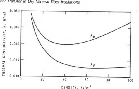
anisotropy factor [2]. Figure 3 illustrates the effect of fiber orientation,1
showing thermal conductivity,A,,
perpendicular, andA,,
parallel, to the0 . 0 5 0 I I I I x E F I N E N E S S I N D E X o F-6.616gl. ( 4 - 1 2 p m )
-
F - f 8 1 5 g ) . ( 4 - 6 p m l 2- Fm3.613g). ( 4 - 3 p m l c F-2.813g). ( 9 - 2 5 p m l 0 . 0 4 0 3 CI Z 0 U 2 I C 8 0 . 0 3 0 1 I I 1 I 0 20 4 0 6 0 8 0 1 0 0 120 D E N S I T Y . kg/rn3Figure 2. Thermal conductivity at 297 K as a function of density and fineness index (From Fournier and Klarsfeld [2]). Copyright, ASTM, 1916 Race Street, Philadelphia, PA 19703. Reprinted with permission.
*The fineness index, F, is defined by a specified air permeability measurement on a ran- domly compacted mineral fiber specimen with a given mass [2].
Heat Transfer in Dry Mineral Fiber Insulations
D E N S I T Y , k g l m 3
Figure 3. Thermal conductivity as a function of density and orientation, AH = parallel,
A, = perpendicular, to the stratification planes. (From Klarsfeld [I]) Copyright, ASTM, 7976 Race Street, Philadelphia, PA 79703. Reprinted with permission. planes of fiber stratification. The three characteristics describe the struc- ture of fibrous material in a unique way, but they do not provide, by themselves, a sufficient basis for predicting the thermal conductivity of the fibrous insulation. The use of semi-empirical models that take into consideration structure and physical characteristics is a more efficient means of predicting thermal performance of mineral fiber insulations.
SEPARATION OF MECHANISMS OF HEAT TRANSFER IN MFI
As discussed in Appendix
A,
convective heat transfer may be neglected for most MFI materials or at near ambient temperature. If interactions among the different modes of heat transfer can be neglected or incorporated underone
of the modes, the total heat flux becomesUnder these conditions, one may add the components due to conduc- tion in gas,
&,
and solids,&,
as well as that due to radiation, A,, to obtain the net conductivity, k,, i.e.,O . 0 5 O l I , I , I I I 1
TQIhl MAT WNSAR
0.040
-
E-
%a
A 4 2 0.030-
> HEAl "TRANSFER %IN GAS -A
i
-
C U 3 0 Z-
0 20 40 60 80 100Figure 4. Heat transfer mechanism in a glass fiber insulation (7 = 20°C, @ = 5 pn) (From Bankvall [3J. Copyright, ASTM, 1916 Race Street, Philadelphia, PA 19703. Reprinted with permission.
analysis of contributions from radiation, and conduction through the gaseous and solid phases. in principle, the contribution of each of the mechanisms of heat transfer is similar to that shown by Verschoor and Greebler [4], except that natural convection does not
appear
in most a e s . Bankvall [3] introduced three structural parameters, r;, E, and a, in addition to total porosity, E . These structural parameters definethe
organization of the solid. Their relation is shown in Figure 5, which il- lustrates that a denotes the part of the material considered tobe
"parallel" to the heat flow lines and I-a the part considered to be "in series" with respect to heat flow. & andq,
denote volume fraction (porosity), corresponding to the series and parallel heat transfer, respec- tively. Total porosity can be expressed as follows:The three structural parameters together with the thermal conductivi- ty of the solid matrix,
&,
and that of the gas,&
allow Bankvall [3] to describe solid and gas contributions of thermal conductivity as follows:Heat Transfer in Dry Mineral Fiber Insulations
Figure 5. Structural parameters in hnkvall's model [3] shown for one unit of volume (From Bankvall[3l).
Table 1 shows the significance of each of the three components in equation 3, based on Bankvall's structural coefficients [3]. The last col- umn relates to another model in which solid and gas fractions of ther- mal conductivity are described by two components only: gas conduc- tivity and the solid plus interactive component. This model will be described by equation 6 where A =
4
and B =(a
+
&JQ. Bankvall's data (Table1)
indicate that the parameter B is approximately constant and independent of density.In experiments on separation of heat transfer mechanisms in low- density fibrous insulation Pelanne [5] assumed that the following terms may be treated as additive components of the apparent thermal con- ductivity:
4
= gas conductivity&
= contribution of gas convectionTable 1. Significance of heat transport contributions calculated from Bankvall's data f31.
ConMbutions, percent
4
k
nB
%
v =
k + k
-
Density Solid Gas Send k2
A,
= solid gas conduction&
= radiation absorption and reemission of the fibersb
= radiation transmission (i.e., radiation transmitted by scattering)A
= interaction of different mechanismsUsing plates with different emittances (E = 0.95 and E = 0.08) in a
vacuum and in air, Pelanne [5] separated the contributions of radiation, solid, and air. Other than
&,
the term&
is the most significant at den- sities lower than 30 kglm3, whereas&
and&
appear to be almost con- stant and of a magnitude comparable to that ofA.
This research by Pelanne [5], as well as previous work, was carried out on one specimen thickness and did not permit extrapolation to other thicknesses. Hollingsworth [6], however, undertook an experimental determination of the thickness effect using a specially constructed large scale apparatus. The experimental data were examined by Bhattacharyya [7], who used the following equation for the radiative part of thermal conductivity:
where
TM = ?h
r[;(
+
Tc)TD=% (TH -TC)
~f;tr
EC
= hot and cold plate emissivityN'
= specific scattering coefficient, m21kgo = Stefan-Boltzmann constant, 5.67 x Wlm2 K4 L = specimen thickness, m
a = material density, kglm3
N
= qN', called a scattering coefficient, mYm3.Equation 4 is based on the two-flux model introduced by Schuster and developed by Hamaker (see Timmermans et.al. [a]). This equation was also used by Larkin [9] and Churchill
[lo]
in studies of radiation through fibrous and foamed insulating materials. The model takes into con- sideration two optical parameters of the material: scattering, N, and ab- sorption, PI coefficients. Equation 4, based on complete scattering, P = 0, shows that when radiation plays a significant role in heat transfer, apparent (measured) thermal conductivity depends not only on material parameters but also on the conditions of the test, TH, Tc, E,,, andHeat Transfer in Dry Mineral Fiber Insulations
Studies by Poltz [Il], Jones [12], Lao and Skochdopole [I 31, Rennex
[14], and Shirtliffe [15], Fine et.al. [I61 discussed thermal resistance at a given mean temperature as a linear function of specimen thickness
The intercept, A, often called R,,, and the slope, B, sometimes called
Rw, are also related to the radiative characteristics of the material.
References 14 to 16 provide detailed discussion of these characteristic properties.
SEMI-EMPIRICAL MODEL O F HEAT TRANSFER IN MFI
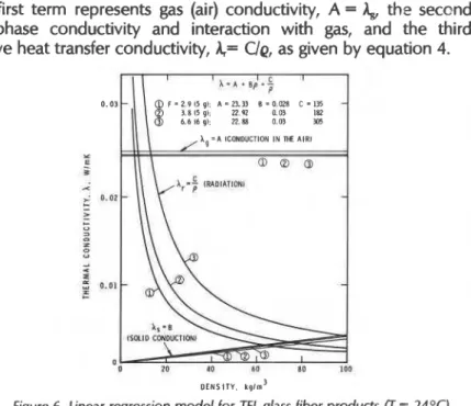
The results of linear regressions for three MFI materials with different surface areas or fineness indices are shown in Figure 6. The regression analysis was performed by Klarsfeld [I71 using the following equation:
C A = A + B q + -
4 (6)
The first term represents gas (air) conductivity, A =
&
the second,solld phase conductivity and interaction with gas, and the third,
radiative heat transfer conductivity,
A=
Uq, as given by equation 4.D I N S I T Y . k q l m 3
Figure 6. Linear regression model for TEL glass fiber products (T = 24OC)
BOMBERC & KLARSFELD
Equation 4 is based on complete scattering, P = 0. Such an assumption may overestimate the reduction of thermal conductivity for small thicknesses, i.e., 10 to 25 mm. Another approach, postulated by Fine, et.al. [16], could be more suitable for thin layers of materials with a significant fraction of absorption (P # 0).
Following this so-called threeregion estimate, one may introduce an additional term into equation 4 (compare [18]). The model becomes:
B, N',
Lo
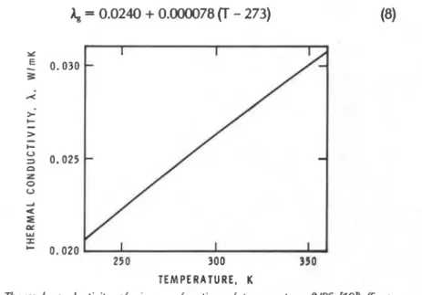
= parameters determined from thermal conductivity measurements. L, is defined from the third term of equation 7, a term supplemental to the fourth term that describes only the scattering model.Figure 6 shows that the B coefficient is practically independent of the fineness index, so that for practical use in lowdensity glass fiber (LDGF) insulations one may use a constant coefficient B = 4.0 x In the temperature range of 250-350 K air conductivity may be assumed to be [I91 (see Figure 7):
TEMPERATURE, K
, Figure 7. Thermal conductivity of air as a function of temperature (NBS 1191 (From
Bankvall 131. Copyright, ASTM, 1916 Race Street, Philadelphia, PA 19103. Reprinted with permission.
Heat Transfer in Dry Mineral Fiber Insulations
Parameters N' and L,, must be determined from a curve fit of A = A(L) for a given set of boundary conditions.
EXPERIMENTAL VERIFICATION OF MODEL
Pelanne [20] introduced the experimental use of paper septa between
layers of lowdensity glass fibers to separate the effects of thickness and
systematic equipment errors in thermal transmission measurements. Placing a radiation barrier n times in a material thickness, L, will modify equation 7. Thickness, L, will now represent the distance between sep- ta, and the number of septa, n, must be introduced in the third term of equation 7. Equation 7 then becomes:
where I I
1 =a term assumed to describe the decreasing significance of
1-
0 n
+
I each added absorptive septum on the total amount ofabsorption caused by all the septa placed in the specimen.
n = number of septa
L = distance between septa, or in their absence, distance between hot
and cold plates.
Table 2 gives
the
calculated values of A based on equation 9, withq, = = 0.95 and measurements on 8
kglm3
LDCF. Although the densi-ty of the specimens varied from 7.9 to 8.8 kglm3, some reduction of the
effects caused by material variability was achieved by averaging the test
results obtained
for
different specimens. Two tests on three specimensand three tests on two specimens were averaged.
Table 3 compares results measured by Pelanne I201 and calculations
obtained
with equation 9, where parameters
N' and L, were experimen-tally determined. Although calculations shown in Tables 2 and 3 agree
relatively well
and describe the effects of changes in mean temperature,
thickness of the specimen, and density of the specimen Table 4 shows
that the thermal conductivity calculated from equation 9 falls far below
Table 2. Thermal conductivity of specimen or stack of specimens,
measured and predicted using equation 9. Tests performed at NRC on
LDGF
specimens with density 7.9 to 8.8 kg/m3 (8.34 mean).Specimen Numbers Average Temperature Measured Calculated
crest No. of Thiiness T, and Tc
&,
364-1 291 Se~ta m OC Wlmk Wlmk k d 1,2,3,4,5,6 0 0.15246 34.94, 12.91 0.0510 used for 1,2,3,4,5,6 5 0.15298 38.90, 13.30 0.0497 N' and L, 1.2.3 and 4.5.6 0 0.075% 34.80. 13.01 0.0504 determination 1,2,3,4,5,6 5 0.15298 51.50, 29.90 0.0545 0.0551 1,2and3,4,and5,6 0 0.05008 34.83,13.37 0.0491 0.0497 1 and 2 0 0.02503 34.85, 13.43 0.0478. 0.0479
I the measured values for surfaces with low emittance. Such an effect
may be expected since L, factors calculated in Tables 2 and 3 were a
I
I few times smaller than expected from a knowledge of the extinction length for the materials tested. Thus equation 9 is limited to use for
emittance close to that of a black body. It is not clear whether the N'-value determined from the regression models or the least squares estimate of equation 9 relates to both absorbed and reemitted radia- tion, or whether absorption was really negligible for the MFI tested.
I
CONCLUSIONAlthough equation 9 cannot be used to distinguish between the two
components of the radiative heat transport, it appears to be a useful
means of predicting thermal conductivity, taking into consideration parameters characterizing the fibrous material and boundary conditions Table 3. Thermal conductivity for specimen stuck with and without
paper septa, measured by Pelanne [20] and predicted by equation 9,
pH
= 37.8OC,Tc
= l o . o O c , 6~ = = 0.95). Specimen DensityWm3
3.6 3.6 3.6 4.8 4.8 4.8 Thickness m 0.0508 0.0508 0.0754 Number of Measured paper Septa WImKn,
0 0.0698 1 0.0620 0 0.061 3 Calcuhtedn,
WlmK N' = 33.50 m21kg L, = 0.034 mmHeat Transfer in Dry Mineral Fiber Insulations
Table
4.
Thermal conductivity, WImK, measured with golden or blackGHP surfaces and calculated by means of equation 9.
MF
Insulation Afrom Pelanne [5], (L = 25.4 mm, T,,, = 23.9OC).
r = 0.95 c = 0.08
Density
Wm3 kteasured Cakuhtd Measured Calculated
N = 27.19 rnYkg
L = 0.08 mrn
in standard guarded hot plate or heat flow meter test methods. It per- mits one to adjust the experimental data to obtain values that would
be
appropriate for selected conditions of specimen density or thickness as well as for various mean temperatures, i.e., all the uncertainties in- volved in sampling and testing procedures.
REFERENCES
1. . Klarsfeld, S., "La conductlv~te des isolants fibreux en fonction de leur struc- ture," Cahiea du Centre Scientifique et Technique du Batiment, No. 213, Cahier 1669, 38-50 (Oct. 1980).
2. Fournier, D. and Klarsfeld, S., "Some recent experimental data on glass fiber
' insulating materials and their use for reliable design of insulations at low
temperatures," American Society for Testing and Materials, STP 544, 223-242 (1974).
3. Bankvall, C., "Heat transfer in fibrous materials," lournal of Testing and Evolution, Vol. 1, No. 3, 235-243 (May 1973).
4. Verschoor,
J.
D. and Greebler, P., "Heat transfer by gas conduction andradiation in fibrous insulations," Trans. ASME, 961-968 (Aug. 1952). 5. Pelanne, C. M., "Experiments on the separation of heat transfer
mechanisms in low-density fibrous insulation," Thermal Conductivity, Plenum Press, 897-91 1 (1969).
6. Hollinsgworth, Jr., M., "Experimental determination of the thickness effect in glass fiber building insulation," American Society for Testing and Materials, STP 718, 255-271 (1980).
7. Bhattacharyya, R. K., "Heat transfer model for fibrous insulations,"
American Society for Testing and Materials, STP 718, 272-286 (1980).
8. Timmermans, G., van Paemel,
O.,
and Myncke, H., "Radiant heat transfer inporous media," 15th Int. Congress of Refrigeration, Venice, 23-29 Sept. 1979, Com. B1 -52, p. 1-6.
sulating materials," Ph.D. Thesis, University of Michigan, University Microfilms Int., 1-169 (1957).
10. Larkin, 8. K. and Churchill, S. W., "Heat transfer by radiation through porous insulations," A.1.Ch.E. lournal, Vol. 5, No. 4, 467-474 (Dec. 1959). 11. Poltz, H., "Einfluss der Warmestrahlung auf die lsolierwirkung poroser
Dammschitchten," Allgemeine Warmetechnik, Vol. 11, 64-71 (1962). 12. Jones, T. T., 'The effect of thickness and temperature on heat transfer
through foamed polymers," 7th Thermal Conductivity Conference, 1967, N.B.S. Spec. Publ. 302, 737-749 (Sept. 1968).
13. Lao, B. Y. and Skochdopole, R. E., "Radiant heat transfer in plastic foams," Proceedings, Society of Plastics Industry, 4th International Cellular Plastic Conference, Montreal, 175-182 (1976).
14. Rennex, 8. C., "Thermal parameters as a function of thickness-for com- bined radiation and conduction heat transfer in lowdensity insulation," lournal Thermal Insulation, Vol. 3, 37-63 (July 1979).
15. Shirtliffe, C. J., "Effect of thickness on the thermal properties of thick specimens of lowdensity thermal insulation," American Society for Testing and Materials, STP 718, 36-50 (1980).
16. Fine, H. A., Jury, S. H., Yarbrough, D. W. and McElroy, D. L., "Analysis of heat transfer in building thermal insulation," Oak Ridge National Laboratory, TM-7481 (Dec. 1980).
17. Klarsfeld, S., "La conductivite thermique des isolants fibreux en relation avec leur structure," Compte rendus scientifiques, Croupement Univer- sitaire de Thermique, Paris (1976).
18. Linford, R. M. F., Schmitt, R. J. and Hughes, T. A., "Radiative contribution to the thermal conductivity of fibrous insulations," Heat Transmission Measurements in Thermal Insulations, American Society for Testing and Materials, STP 544, 68-84 (1974).
19. 'The thermal insulating value of airspaces," U.S. Housing and Home Financ- ing, Housing Research Paper 32 (April 1954).
20. Pelanne, C. M., "Discussion on experiments to separate the effect of thickness from systematic error." American Society for Testing and Materials, STP 71 8, 322-334 (1 980).
21. Combarnous, M. and Bories, S., "Hygrothermal convection in saturated porous media," Advances in Hydroscience, Vol. 10, Academic Press,
I 231 -307 (1975).
22. Cambarnous, M., "Natural convection in porous media and geothermal
I systems," 6th Int. Heat Transfer Conf., Toronto, Vol. 6, 45-59 (August
I 1978).
I
23. Klarsfeld, S., "Application de resultats recents concernant la convecti naturelle en milieux poreux a la prevision du compartment thermique de parois isolants," 13th Int. Congress of Refrigeration, IIR Proc. Vol. 2, Com. 82 (2.51) 37-46 (1971).
24. Sc'7uyler,
G.
D. and Solvason, K. R., "Effectiveness of wall insulation," American Society for Testing and Materials, Presented DOEIASTM Thermal Insulation Conference (Dec. 1981).Heat Transfer in Dry Mineral Fiber insulations
ACKNOWLEDGEMENT
The authors would like to express deep gratitude to Marie-Pierre Barthe, Research Director of lsover Saint-Gobain, who initiated the research cooperation between our two research centers. This paper is a contribution from the Division of Building Research, National Research Council Canada, and is published with the approval of the Director of the Division.
APPENDIX A. NATURAL CONVECTION
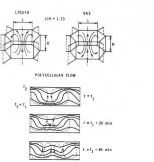
Heat transfer from a solid body through an adjacent layer of fluid can be increased if the fluid moves with respect to the solid material. The phenomenon is usually called heat convection. Figure A-I, a and b, from Cambarnous and Bories [21], shows characteristic structures of convective movements in horizontal and inclined layers of fibrous and porous materials. Heat transfer by convective fluid movement can be predicted with the help of relations utilizing dimensionless numbers. These numbers contain the physical parameters that describe the phen- omenon in various stages of evolution.
Dimensionless numbers associated with heat convection in fibrous media are as follows:
1) Rayleigh filtration number, Ra*:
where
g = f(T.), are the properties of the interstitial fluid at a given temp- erature, namely,
g = acceleration due to gravity, mls2,
fl
= volumetric expansion coefficient of fluid, K-',v kinematic viscosity of fluid, m21s,
(gc),
= heat capacity of fluid, Jlm3 K, 4Kvbratio characterizing the fibrous medium, aniso- [(L*Kv)ID + ( ~ * w ' ] ' tropic in thermal conductivity and permeability. Kv, K,, = vertical and horizontal permeability of the medium, m2
Av*, A,.,* = vertical and horizontal thermal conductivity with unmovable :
interstitial fluid, W1m.K I
S.
POLYCELLULAR FLOW
Figure A-la. Structure of convective movements in layers of horizontal porous materials (From Combarnous and Bories [27J.
.
-
.
+. r 1 - T 2 MOHUCFLLILAR FLOW r ~ Z T 2 R O L L F L O WFigure A-lb. Structure of convective movements in inclined layers of porous materials (From Cornbarnous and Bories [ZI]).
Heat Transfer in Dry Mineral Fiber insulations
AT, Tm = temperature difference, mean temperature, K
d =
characteristic distance, e.g., distance between hot and cold platesof the thermal conductivity test apparatus, m 2) Aspect ratio:
A = l l d
where l = height, d = width of vertical cells,
3) Nusselt filtration number, Nu*:
where I
4
= heat flow rate, including heat transfer caused by convection (+* =the same but without contribution of convection).
A, A* = thermal conductivity with and without interstitial fluid move ment, respectively.
When the Nusselt number is equal to one, heat transfer does not con- tain any contribution from convection. In the presence of ccnvective
movement,
4
is greater than 4* and the Nusselt number becomesgreater than one.
Heat transfers with natural convection in horizontal, vertical, or inclin-
ed layers by a general equation of the following type:
Nu* = f(Ra*, A, cos a)
The relation between Nusselt number and flow conditions is either en- tirely experimental or semi-empirical. The remarkable fact is, however, that a transition from one type of flow to another always occurs at the same values of dimensionless numbers, independent of the porous medium in which convection takes place. These numbers are called critical numbers. They depend on geometrical configuration, temperature differences, and assumptions made regarding the in- terstitial gas properties. For example, in a horizontal layer with heat flow
upwards, convection will not occur (Nu = 1) if
Ra* is smaller than 40 for small AT, or AT
Ra* is smaller than 40-6
-
for large AT (Combarnous [22])Tm
I I I I 1 I I I 1
-
-
, A A L C I I I r n O 0 4 I I 1 10 2 0"
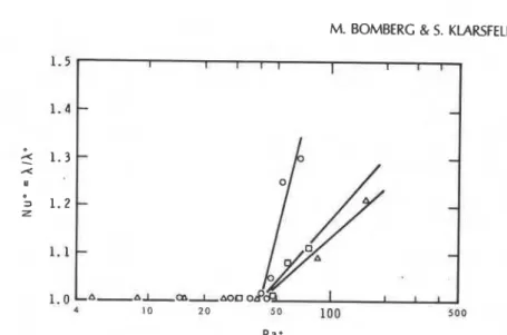
1100 5 0 0 R a eFigure A-2. Nusselt number (Nu*) as a function of Rayleigh number for filtration (Ra*) in a plane horizontal layer immersed in water. Three types of glass fiber insula- tions are shown (From Klarsfeld [I]).
In plane, horizontal layers the convective movement starts suddenly at a given threshold level, as shown in Fig. A-2. In other geometrical con- figurations (vertical, inclined layers) convective movement grows grad-
ually with temperature difference
[23]
(as shown in Fig. A-3). At first themovement is slow and the heat transfer is pseudo-convective. Later,
Ra* 37.9; Ram
-
324.5; Ra*-
649.0: Ra*-
1622.5:Nu* = 1.5 Nu* - 6 . 0 Nu* = 8.2 Nu*
-
13.4Figure A-3. Thermal field associated with convective movements in a vertical cell filled with glass fiber (From Klarsfeld [23]), a: asymptotic conditions; b,c: in- termediate conditions; d: separate limit layer conditions.
Heat Transfer in Dry Mineral Fiber Insqlations
movement accelerates as a function of mean temperature and tempera- ture difference up to the point at which a change of regime occurs, as described by the transition criteria.
Users of fibrous insulation must determine to what extent the material may exhibit convection in a particular set of use conditions (thermal and geometrical). It is necessary to know the parameters describing the porous medium (solid matrix and interstitial fluid). The following means may be used by a manufacturer to ensure that Ra* value will not exceed the critical value:
1) Material permeability may be reduced by either changes in porosity
(density) and/or volumetric surface (fineness).
2) Thickness of the layer may be reduced by use of impermeable screens.
3) A combination of points 1) and 2) may be achieved when using
layered products.
For building applications, both computations and experimental data show that for all currently used types of mineral fiber insulations there is either no convection or an asymptotic or pseudo-convective regime if 1) the insulation fills the space completely and 2) it is enclosed by two air- impermeable surfaces.
Natural convection becomes important in cryogenic applications (low mean temperatures) and for larger temperature differences. It can also be amplified by forced convection if the wall system does not provide proper measures for controlling air movement. These problems are, however, beyond the scope of material manufacturers and must be dealt with at the building design stage (see discussion by Schuyler and Solvason [24]).
Bullding R e s e a r c h of t h e N a t i o n a l R e s e a r c h Council of Canada. I t s h o u l d n o t b e r e p r o d u c e d in whole o r i n p a r t without p e r m i s s i o n of t h e o r i g i n a l p u b l i s h e r . T h e D i - v i s i o n would b e g l a d to b e of a s a i s t a n c e i n obtaining s u c h p e r m i s s i o n . P u b l i c a t i o n s of t h e Division m a y b e o b t a i n e d by m a i l - ing t h e a p p r o p r i a t e r e m i t t a n c e (a Bank, E x p r e s s , o r P o s t O f f i c e Money O r d e r , o r a cheque, m a d e p a y a b l e t o t h e R e c e i v e r G e n e r a l of Canada, c r e d i t NRC) t o t h e N a t i o n a l R e s e a r c h C o u n c i l of Canada. Ottawa. K1A OR6. S t a m p s a r e n o t a c c e p t a b l e .
A l i s t of a l l p u b l i c a t i o n s of t h e Division i s a v a i l a b l e a n d m a y b e obtained f r o m the P u b l i c a t i o n s S e c t i o n , Division of Building R e s e a r c h , N a t i o n a l R e s e a r c h C o u n c i l of C a n a d a , Ottawa. KIA OR6.


![Figure 5. Structural parameters in hnkvall's model [3] shown for one unit of volume (From Bankvall[3l)](https://thumb-eu.123doks.com/thumbv2/123doknet/14319204.496722/9.606.179.504.93.333/figure-structural-parameters-hnkvall-model-shown-volume-bankvall.webp)