Publisher’s version / Version de l'éditeur:
Transportation Research Record, 576, pp. 20-32, 1976
READ THESE TERMS AND CONDITIONS CAREFULLY BEFORE USING THIS WEBSITE. https://nrc-publications.canada.ca/eng/copyright
Vous avez des questions? Nous pouvons vous aider. Pour communiquer directement avec un auteur, consultez la première page de la revue dans laquelle son article a été publié afin de trouver ses coordonnées. Si vous n’arrivez pas à les repérer, communiquez avec nous à [email protected].
Questions? Contact the NRC Publications Archive team at
[email protected]. If you wish to email the authors directly, please see the first page of the publication for their contact information.
NRC Publications Archive
Archives des publications du CNRC
This publication could be one of several versions: author’s original, accepted manuscript or the publisher’s version. / La version de cette publication peut être l’une des suivantes : la version prépublication de l’auteur, la version acceptée du manuscrit ou la version de l’éditeur.
Access and use of this website and the material on it are subject to the Terms and Conditions set forth at
Design heat requirements for embedded snow-melting systems in cold
climates
Williams, G. P.
https://publications-cnrc.canada.ca/fra/droits
L’accès à ce site Web et l’utilisation de son contenu sont assujettis aux conditions présentées dans le site LISEZ CES CONDITIONS ATTENTIVEMENT AVANT D’UTILISER CE SITE WEB.
NRC Publications Record / Notice d'Archives des publications de CNRC:
https://nrc-publications.canada.ca/eng/view/object/?id=96fc18a1-0323-4a8c-a1c7-132be10fe502 https://publications-cnrc.canada.ca/fra/voir/objet/?id=96fc18a1-0323-4a8c-a1c7-132be10fe502
S e r
!TH1
N 2 1 d
INational Research Conseil national
n o *
7 1 5
8
c
ouncil Canada de recherches Canadac . 2
BLDG
1
1 1
DESIGN HEAT
\REQUIREMENTS FOR
EMBEDDED SNOW-MELTING SYSTEMS
.:
IN COLD CLIMATES
by G.P. Williams
Reprinted from
Transportation Research Record 576 (1976)
Transportation Research Board
Washington, D.C. p. 20 32 1
.
,2\"{%ED.
k,Ca
1.- *-DBR
F a ~ e r No.715
I Division
bf
Building
Research
DESIGN HEAT REQUIREMENTS FOR EMBEDDED
SNOW-MELTING SYSTEMS IN COLD CLIMATES
by G. P. Williams
Reprinted from Transportation R e s e a r c h Record 576 (1976) Transportation Research Board, Washington, D. C.
DESIGN HEAT REQUIREMENTS FOR EMBEDDED
SNOW-MELTING SYSTEMS IN COLD CLIMATES
G. P. Williams, Division of Building Research, National Research Council of Canada Methods of calculating design heat requirements of embedded snow -melting systems a r e assessed, particularly for those operating in cold climates. Formulas for estimating design heat requirements developed from snow- melting tests carried out during three winters at Ottawa, Canada, a r e compared with those recommended in the Guide and Data Book of the American Society of Heating, Refrigerating, and Air-Conditioning Engi- neers (ASHRAE), the only comprehensive guidelines available in North America. The relation between convective coefficients and wind speed at an exposed s i t e compares reasonably well with that recommended by ASHRAE, provided adjustments a r e made f o r the size of the heated area, the exposure to wind, and the height at which wind speeds a r e measured. Evaporative coefficients recommended by ASHRAE also need to be adjusted for the size of heated a r e a and the exposure to wind. Radiative coefficients need to be adjusted for cloud conditions. The design heat requirements f o r systems operating in cold climates a r e determined by the maximum rate of surface heat loss from bare, wet pavements for weather conditions that will probably prevail immediately after snowstorms. Design heat require- ments calculated for an exposed site at Ottawa by using the heat transfer coefficients obtained a r e 170 ~tu/ft'-hour (536 w/rn2). This agrees quite
well with current practice in this region. Two case histories of snow-
melting tests a r e presented to illustrate that the use of insulation will practically eliminate ground heat loss and the need to allow for i t in design calculations.
'ONE of the more difficult determinations in the design of embedded heating systems in pavements i s the calculation of the heat needed to prevent ice from forming o r snow from accumulating. Designers must provide sufficient heat capacity for effective melt- ing but must not overdesign the system and unnecessarily increase the cost of an already expensive operation.
Published information on procedures f o r calculating design heat requirements i s limited and can be misleading. Some of the procedures a r e based on field tests of snow
melting during mild weather (1,2) and do not necessarily apply to systems operating
-
-under severe winter weather. The procedure recommended in the ASHRAE Guide and Data Book (3), the only comprehensive guideline available in North America, has proved to be of uncertain value. A comparison of calculated design heat loads, based on pro- cedures .of the American Society of Heating, Refrigerating, and Air-Conditioning Engi- neers (ASHRAE), with actual installed heat capacities for five cities in the northern
United States (41, shows that the installed heat capacities a r e often quite different from
the theoreticalvalues
able
1). The information on installed capacities, shown for .Canada, was obtained from unpublished and published reports (5,6). Installed heat capacities a r e generally somewhat lower in Canada than those reported in the United States, a surprising development considering the more severe climatic conditions under which Canadian systems usually operate.
The purpose of this paper i s to a s s e s s methods of calculating design heat require- ments of embedded snow-melting systems, particularly those operating in cold climates. The study is based on an extensive review of the literature and on snow-melting tests
2 1
1
c a r r i e d out on heated pavements, o v e r t h r e e winter periods, on the grounds of theNational R e s e a r c h Council of Canada i n Ottawa.
TEST SLABS, INSTRUMENTATION, AND WEATHER OBSERVATIONS
i
Test s i t e s A, B, and D a r e shown in Figure 1. Most of the observations w e r e made a t
' of Canada
I
s i t e A, a 16-ft2 (1.5-m2) electrically heated, insulated snow-melting s y s t e m a t an ex-posed location. E l e c t r i c heating cables, spaced 4 in. (10.2 c m ) apart, w e r e embedded
nel'c'ing 3 in. (7.6 cm) deep in a 7.5 in.-thick (19-cm) concrete s l a b that rested on 2 in. (5.1 cm)
mates. of expanded polystyrene insulation. The heating cables w e r e laid out in two separate
snow- c i r c u i t s , providing two heated a r e a s : a n i n n e r 10-ft2 (0.9-m2) a r e a in the center of the
a, a r e s l a b and an o u t e r 2.5-ft-wide (0.75-m) a r e a extending around the inner .area. Three
of the levels of power input w e r e available f o r each c i r c u i t . T e m p e r a t u r e s w e r e measured
Engi
-
by thermocouples at s e v e r a l locations i n the concrete s l a b and i n the insulation underNorth the s l a b . Heat l o s s through the insulation was m e a s u r e d by heat flow m e t e r s installed
eed a t a t t h r e e locations i n the insulation. A data logging s y s t e m w a s used to r e c o r d output
ed by f r o m t h e thermocouples and heat flow m e t e r s .
a r e a , Observations w e r e a l s o made a t two heated 3-ft2 (0.3-m2) concrete t e s t s l a b s : One
s u r e d . w a s located a t a n exposed s i t e B, the o t h e r a t s i t e C, s h e l t e r e d f r o m the wind. The
Ijusted two s l a b s w e r e identically constructed: 1-in.-thick (2.5-cm) concrete with embedded
'cients i e l e c t r i c heating cables and with 1-in.-thick (2.5-cm) polystyrene bead board insulating
t s f o r the bottoms and s i d e s . T e m p e r a t u r e s w e r e m e a s u r e d a t s e v e r a l locations in both
n r a t e concrete and insulation by thermocouples attached to r e c o r d e r s . The power input was
s that.
I
recorded and controlled to maintain the s u r f a c e t e m p e r a t u r e of each s l a b a t about 38 Fquire- (3.3 C) during t e s t runs. Site B was located on t h e north s i d e of a s m a l l building a few
a n s f e r hundred f e e t ( m e t e r s ) f r o m s i t e A. The s l a b a t s i t e C w a s located on the south s i d e of
7 quite the s a m e building, a l m o s t completely s h e l t e r e d f r o m wind by the building and by a fence
snow- built f o r that purpose. Observations
at
t h e s e s i t e s w e r e used to determine the effect ofn ?.ill s i z e and exposure on the heat requirements of snow-melting s y s t e m s .
design Limited observations w e r e a l s o obtained a t s i t e D, a n electrically heated r a m p lead-
ing to the basement of a building located on the grounds of the National Research Council of Canada. This uninsulated snow-melting s y s t e m i s operated intermittently, and the
g s y s t e m s i n
I
power is automatically turned on a t 5 p.m. and off at 8 a.m. during the winter season.o r snow Surface t e m p e r a t u r e s w e r e m e a s u r e d a t s e v e r a l locations on the r a m p by means of
'fective melt- thermocouples connected to a r e c o r d e r , and s u r f a c e heat l o s s w a s determined by a heat
t of an a l r e a d y flow m e t e r installed i n the asphalt s u r f a c e . The power input was measured by the
1
household types of w a t t m e t e r s on the c i r c u i t s supplying power to the ramp. Observa-ments i s tions w e r e used to d e t e r m i n e the magnitude of heat l o s s to the ground a t this site.
t e s t s of snow Standard weather r e c o r d s obtained on the grounds of the National Research Council
operating of Canada, t h e only kind of weather information normally available f o r design calcula-
Guide and
!
tions, w e r e used i n the analysis. A i r t e m p e r a t u r e was m e a s u r e d with a thermocouplea, h a s proved located in a Stevenson s c r e e n about 200 f t (61 m ) f r o m s i t e A; wind speed was recorded
s e d on p r o -
I
with a n a n e m o m e t e r located a t a height of 50 f t (15.2 m); snowfall measurements, ob-ioning Engi-
1
tained by standard meteorological methods, w e r e checked with a recording gaugenorthern equipped with a windshield; and net radiation, m e a s u r e d with an all-wave radiometer
'ferent f r o m installed about 2 f t (0.6 m ) above the c e n t e r of the s l a b a t s i t e A, was used to check
;hown f o r radiation f o r m u l a s . Surface conditions on the heated s l a b s (whether they w e r e dry, wet,
led heat
I
snow- o r ice-covered) during t e s t s r u n s w e r e obtained by visual observation supple-he United mented by t i m e - l a p s e photographs taken a t s i t e A.
.ditions under
t r e q u i r e - SURFACE HEAT LOSS FROM BARE PAVEMENTS
bold climates.
lting t e s t s Designers of snow-melting s y s t e m s . m u s t e s t i m a t e s u r f a c e heat l o s s f r o m b a r e pave-
ments when determining the heat r e q u i r e d to maintain operating t e m p e r a t u r e s f o r s y s -
t e m s r u n continuously o r the heat needed to r a i s e the t e m p e r a t u r e of a s l a b to operating
!
.
. ,
- . . ,
!
where h, = heat t r a n s f e r coefficient, a function of many v a r i a b l e s , shape, roughness, and dimensions of the s u r f a c e that will not be uniform o v e r a surface. F o r design cal- culations a n a v e r a g e coefficient is used.
Convective heat l o s s Q, of d r y s u r f a c e s w a s determined at s i t e A f o r the selected p e r i o d s f o r t h e c e n t r a l heated a r e a of t h e s l a b f r o m t h e following equation:
w h e r e
I
QT
= e l e c t r i c a l power,Q, = net radiation, and
Q,
= heat flow through the insulation under the slab.All of t h e s e values w e r e m e a s u r e d . Heat l o s s f r o m the edge of the pad w a s kept to a n insignificant level by maintaining an appropriate level of heat input to the outer c i r c u i t of the slab. The periods analyzed w e r e f o r steady s t a t e conditions when t e m p e r a t u r e changes within the concrete w e r e slight and the contribution of heat s t o r a g e
tb
s u r f a c e heat l o s s could be neglected. Average hourly coefficients f o r convective heat t r a n s f e r (&/AT) w e r e then obtained and plotted against a v e r a g e hourly wind s p e e d s f o r s i t e A. A calculated value of convective coefficient f o r f r e e convection (7)-
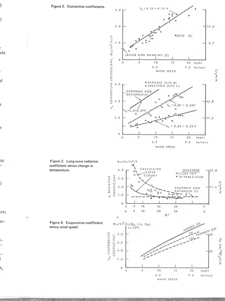
i n the absence of winds is also shown.A s i m i l a r procedure was used to obtain convective coefficients f o r the s m a l l s l a b s a t s i t e s B and C ( F i g u r e 2). Those obtained by Chapman and Katunich (1) f o r 3.5-ft- d i a m e t e r (1.1-m) snow-melting t e s t panels a g r e e quite well with m e a s u r e d values at
s i t e B if adjustments a r e made f o r the height a t which wind speeds w e r e measured. It was not possible to compare other convective coefficients reported i n the l i t e r a t u r e on snow melting because convective and radiative coefficients a r e combined and a r e not reported separately.
~ h e s e r e s u l t s show that the s i z e of a heated a r e a must be taken into consideration in calculating heat l o s s by convection. Convective heat coefficients obtained f o r the s m a l l s l a b a t s i t e B a r e almost double those at the l a r g e r s l a b a t s i t e C f o r the s a m e wind speed. The effect of s i z e on convective coefficients is particularly important f o r a r e a s with s h o r t c h a r a c t e r i s t i c length, such a s narrow sidewalks o r heated wheel t r a c k s , but does not a p p e a r to be too significant f o r l a r g e r heated a r e a s with c h a r a c t e r i s t i c lengths varying f r o m 10 to 100 f t (3.1 to 30.5 m) (8).
These r e s u l t s a l s o show the effect of e G o s u r e to wind. The reduction in heat l o s s observed a t the s h e l t e r e d s i t e C is approximately the s a m e as that recommended by Watkins (9) f o r s h e l t e r e d s i t e s . Adjustments f o r the d e g r e e of exposure to wind should be made Gith caution, however, because wind s p e e d s a r e difficult to p r e d i c t a t specific s i t e s , especially i n urban a r e a s (10). The relation shown i n Figure 2 f o r s i t e C should only be used f o r s i t e s that a r e completely s h e l t e r e d f r o m wind.
Radiative Heat L o s s
Net long-wave radiation (downward a t m o s p h e r i c minus upward t e r r e s t r i a l ) is the only radiative component considered i n the design of snow-melting s y s t e m s . The heat r e - ceived f r o m short-wave radiation during daylight hours is usually not taken into con- sideration in the design calculations because melting s y s t e m s must p e r f o r m s a t i s f a c - torily under the w o r s t conditions, e.g., a t night when a i r t e m p e r a t u r e s a r e lowest and s u r f a c e heat l o s s e s usually g r e a t e s t . .
A f o r m u l a developed by Swinbank (11) f o r estimating incoming long-wave radiation under c l e a r sky conditions and a procedure outlined by Budyko (12) f o r taking into a c - count s u r f a c e t e m p e r a t u r e and cloud conditions provided the bas= f o r two equations f o r estimating net long-wave radiation:
Temperatures a r e measured in kelvins, and the Stephan-Boltzman constant o i s mea- sured in milliwatts/square centimeter ' kelvins (the units used by winb bank).
Equations 3 and 4 were used to calculate the long-wave radiation coefficients, h, = (Q,/A T), f o r both clear and cloudy conditions and a range of a i r temperatures f o r a bare concrete pavement a t 32 F (0
c).
The calculated long-wave radiation coefficients a r e compared with measured coefficients obtained from measurements of Q, over the heated test slab a t site A for selected periods when the sky was either clear o r com-letely overcast and when surface temperatures varied from 32 to 50 F (0 to 10 C) Figure 3). Some of the variation in the measurements can be attributed to uncertain-
P
ties associated with cloud cover, i.e., whether o r not the sky was completely clear of high clouds o r completely overcast. The reasonable agreement between calculated and measured values indicates that equations 3 and 4 a r e satisfactory for estimating radi- ative heat loss in design calculations using the two extreme cloud conditions.
The average radiation coefficient (1) used by ASHRAE i s also shown in Figure 3. This value will give good results i f used for cloudy conditions and large surface-air temperature differences. It should not be used for c l e a r sky conditions o r when A T i s l e s s than 18 F (-10
c).
Radiative and convective coefficients a r e often combined in a surface o r film coef- ficient. The combined coefficients for s i t e A give considerably lower combined heat loss by convection and radiation a t high wind speeds than that calculated by using ASHRAE coefficients. The magnitude of this overestimate will become apparent in the next section of the paper where total surface heat l o s s calculated by the ASHRAE for- mula i s compared with the results obtained at site A.
Evaporative Heat Loss
Numerous empirical equations a r e available for estimating the rate of evaporation f r o m water surfaces under atmospheric conditions. The simple equations developed for en- gineering use a r e of the following form:
where
E = evaporation rate;
k = empirical constant, including a i r density, a i r pressure, and roughness factors; f (v) = function of wind speed; and
A e = difference in vapor p r e s s u r e between the saturation vapor p r e s s u r e at the tem- perature of the surface and the vapor p r e s s u r e of the a i r above the surface. The evaporation rate E can be converted to heat by multiplying i t by the latent heat of vaporization. Difficulties in the measurement of evaporation r a t e s proved insurmount- able at test site A, and i t was necessary to rely on eldsting formulas to estimate evap- orative heat loss from wet pavements.
The empirical evaporation formula used by ASHRAE was compared with one recom- mended by Penman (13), which i s well accepted for estimating evaporation from small water surfaces ( ~ i g u z 4). The agreement between the two formulas i s quite good if i t is assumed that wind is measured a t the 6.6-ft (2.1-m) level. These results suggest, however, that the ASHRAE formula would have considerable e r r o r if wind speeds ob-
Figure 2. Convective coefficients. U is mea-
l.
:nts, , a t u r e s f o r I coefficients I o v e r the o r com- Ila
c)
uncertain- y c l e a r of culated and king radi- .gure 3. 'ace-air ,hen A T is 'ilm coef- .ned heat 1s i ng .rent i n the 'RAE f o r - 1rati6n from ~ e d r f a r en- n e s s f a c t o r s ; z 0 5 1 0 1 5 2 0 ( m p h ) L L-
2 a .5 9 . 0 ( r n / s e c ) LL W I N D S P E E D U LL \ u N 0 \ E U 0 E X P O S E D ( S I T E 8 ) S H E L T E R E D ( S I T E C )Figure 3. Long-wave radiative ~ t u / h r / i 1 2 / ~ coefficient versus change in "? temperature. : a t the tem- surface. nt heat of nsurmount- m a t e evap- me recom- r o m s m a l l e good if Its suggest, ~ e e d s ob- 0 I I I I
I
0 5 l o 1 5 2 0 ( m p h ) 4 . 5 9 . 0 ( r n / s e c ) W l N D S P E E D \ C A L C U L A T E D M E A S U R E D O C L E A R S K Y * 1 0 / 1 0 t h r C L O U Di
/.
.
.
I
\
C H A P M A N A N D;
Figure 4. Evaporative coefficient ~ , ~ / r t ~ / h , / n , ( i n . H ~ ,
versus wind speed. ( X 1 0 7 )
", > & 4 . 0 - ; z 4 : x m = " 3 . 0
-
2
r E E k 7 . 0-
2
2
- 2 5<
0 N = I . O-
E 1 3 0 , 0 5 1 0 I5 2 0 ( m p h ) 4 . 5 9 . 0 ( m / r e c ) W l N D S P E E Dtained f r o m standard weather r e c o r d s [usually measured a t the 3.1-ft (10-m) level] w e r e used to calculate evaporation. The importance of allowing f o r the height a t which wind speed is measured has frequently been s t r e s s e d i n the l i t e r a t u r e (14).
Evaporative coefficients need to be adjusted f o r the s i z e of the evaporating a r e a and the exposure t o wind i n the s a m e way as convective coefficients. One way of doing this is to a s s u m e that Bowen's ratio (15) is valid, i.e.,
-
When convective heat l o s s has been calculated by using the relations shown in Figure 1, evaporative heat loss can be estimated by using Bowen's ratio.
The total surface heat l o s s f r o m wet pavements by convection, long-wave radiation, and evaporation was calculated f o r completely cloudy conditions f o r AT = 18 I?(-10 C) and A e = 0.13 in. (3.3 rnm) of mercury, by using the coefficients obtained a t s i t e A and
weather stations is taken into account, they a g r e e reasonably well with the results ob- tained a t s i t e A.
SURFACE HEAT LOSS DURING SNOWSTORMS
Heat Required to Maintain B a r e Pavement During Snowstorm
Maintainance of completely b a r e pavement during a snowstorm requires that sufficient heat be supplied t o m e l t snow as i t falls and to offset surface heat l o s s by convection, radiation, and evaporation. The heat required f o r melting equals the heat of fusion multiplied by the hourly r a t e of snowfall (water equivalent/hour). Information on the maximum hourly r a t e s that can be expected a t a s i t e is therefore needed. The problem of measuring snowfall r a t e s accurately under windy conditions has not been solved, however, and reliable data on hourly r a t e s a r e not usually available. The few esti- mates available indicate that maximum hourly snowfall may be two to t h r e e times the hourly rate, averaged o v e r the entire period of a snowstorm (16). F o r a n average r a t e of snowfall during a s t o r m of 1.0 in./hour (2.5 cm/hour), the eTtimated maximum hourly r a t e s range from 2 to 3.5 in./hour (5.1
to
8.9 cm/hour), and a heat input of 170 to 275 ~tu/ft'-hour (536 t o 867w/rnZ)
would be required to melt the snow a s i t falls. Sites that a r e subject to drifting snow require even l a r g e r heat inputs since the r a t e a t which snow can drift into a s i t e can be s e v e r a l t i m e s the average r a t e of snowfall. Because of the l a r g e amounts of heat required, snow-melting s y s t e m s a r e seldom designed to maintain completely b a r e pavements during snowstorms. This becomes evident when c l a s s 3 installed capacities a r e compared with ASHRAE calculated values ('Table 1).Design Heat Requirements f o r Snow-Covered Surfaces
Surface heat l o s s e s by convection, radiation, and evaporation a r e reduced i n direct proportion to the percentage of heated pavement covered by snow. If the a r e a is half covered, s u r f a c e heat l o s s e s a r e reduced to about one-half those of a completely b a r e a r e a ; if the pavement is completely covered by even a thin layer of snow, the only s u r - f a c e heat l o s s is the s m a l l amount of heat t r a n s f e r r e d upward by conduction from the pavement surface through the snow cover.
In the ASHRAE procedure f o r calculating design s u r f a c e heat losses, t h r e e levels
n) l e i e l l ght a t which ng a r e a and ~f doing. this i n Figure 1, e radiation, 3 F(-10 C) !t s i t e A and i t h values 1 ) f o r the de- :her values n t h e s e ~t standard r e s u l t s ob-
a r e chosen (level 1, complete snow cover; level 2, 50 p e r c e n t snow cover; and level 3, completely b a r e ) to allow f o r the percentage of a r e a covered by snow. F o r most snow- melting s y s t e m s i n cold c l i m a t e s , however, only level 1 need be considered because level 3 gives unrealistically high heat r e q u i r e m e n t s and the a r b i t r a r i l y chosen level 2 will not n e c e s s a r i l y apply
at
specific s i t e s .Snow-melting s y s t e m s designed to m e l t the a v e r a g e r a t e of snowfall o c c u r r i n g during snowstorms, a s s u m i n g complete snow cover, will prevent excessive snow accumulation, provided drifting snow i s not a problem. Many of the e a r l i e r snow-melting s y s t e m s w e r e designed to m e l t snow at a c e r t a i n design r a t e of snowfall without consideration of any o t h e r f a c t o r s . Even r e c o r d snowstorms (17), with 29.9 in. (76 cm) in 24 hours, only r e q u i r e about 90 J3tu/ft2-hour (284 w/m2) to m x t all the snow o v e r the period of the s t o r m , a s s u m i n g no ground heat l o s s .
The design h e a t r e q u i r e m e n t s f o r snow-melting s y s t e m s should not, however, be based only on t h e i r ability to melt snow during a s t o r m . If too low a design value is used, bridging can o c c u r under undisturbed snow on sidewalks o r driveways with l i t t l e traffic, and subsequent poor heat t r a n s f e r f r o m the heated pavement t o t h e snow c o v e r will r e s u l t . Where t h e r e is vehicle traffic, a portion of the heated pavement will be kept f r e e of snow, and s u r f a c e heat l o s s f r o m the b a r e portion of the pavement will in- c r e a s e heat r e q u i r e m e n t s accordingly. In addition, the limiting condition in cold cli- m a t e s is not s o much the melting of snow during a s t o r m as t h e maintenance of a n ice- f r e e s u r f a c e a f t e r w a r d s .
Design Heat Reauirements After Snowstorm
~t
sufficient onvection, ~f fusion ion o n the Thedproblem solved, 'ew e s t i - t i m e s the l v e r a g e r a t e vimum hourly 170 to 275 Is. Sites a t e a t which.
Because -signed to id'ent whenTable
1). in d i r e c t -ea is half tete-ly b a r e,le
only s u r - 1 f r o m the -ee levelsPreventing i c e f r o m forming on a heated pavement immediately a f t e r a s t o r m r e q u i r e s that t h e heat input to the s u r f a c e be equal to o r exceed the r a t e of s u r f a c e l o s s f r o m a
wet surface. This heat requirement usually exceeds that during a s t o r m because the pavement i s f r e e of snow and s u r f a c e heat l o s s can be quite high, particularly i n cold c l i m a t e s w h e r e s n o w s t o r m s a r e often followed by e x t r e m e l y cold weather.
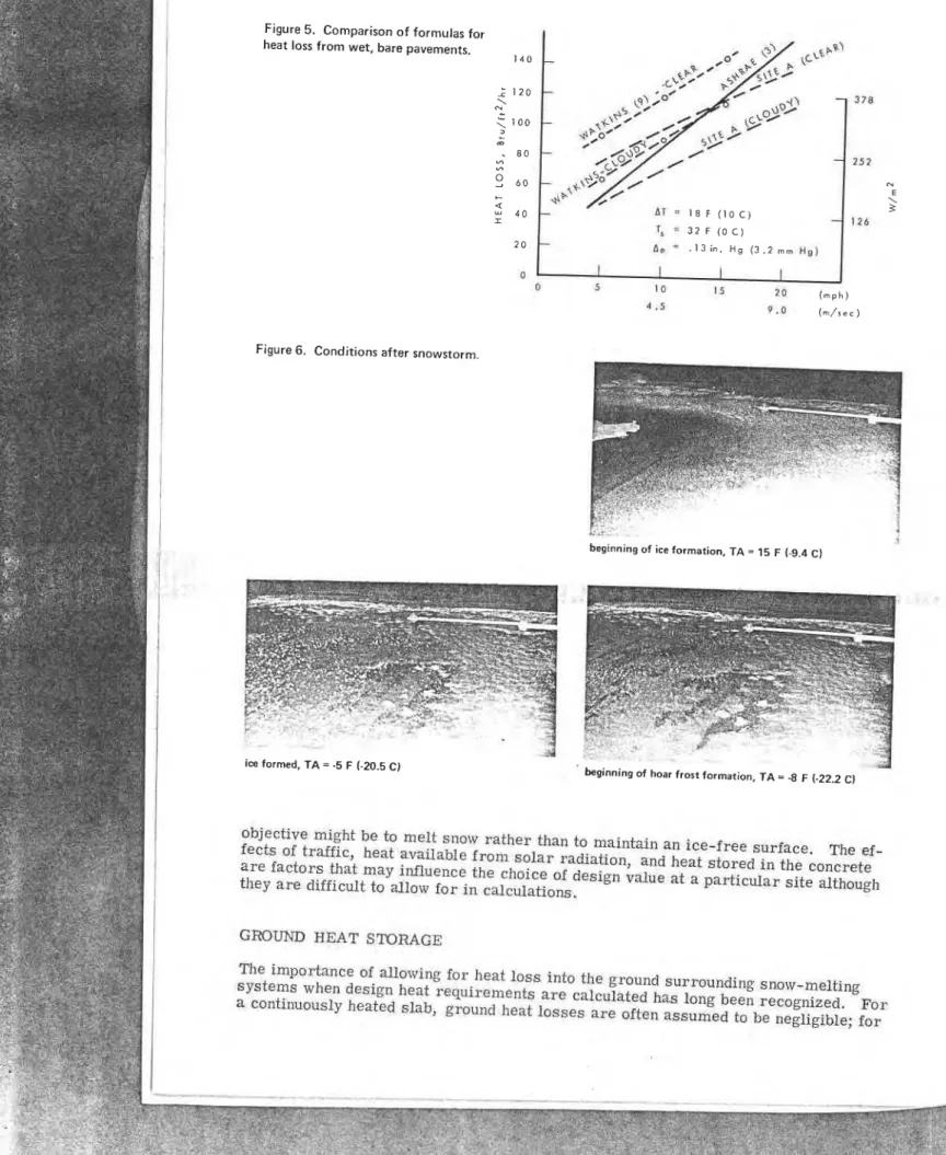
Observations at s i t e A showed that conditions a f t e r a s t o r m w e r e always the limiting f a c t o r i n determining the required heat input. Figure 6, a s e r i e s of time-lapse photo- graphs taken a t s i t e A on January 6, 1973, shows a typical example of i c e formation under s e v e r e weather conditions a f t e r a s t o r m . Immediately a f t e r the s t o r m on the evening of January 5, the s l a b was essentially b a r e and wet. By late evening i t was partially covered with a thin l a y e r of c r u s t e d ice, resulting p a r t l y f r o m light snow blowing on the wet s u r f a c e . By 4 a.m. on January 6, the s l a b was s t i l l covered be- cause t h e r a t e a t which heat was supplied to the s u r f a c e was insufficient to maintain a
I
b a r e s u r f a c e . At 6 a.m. on January 6, hoar f r o s t began t o f o r m and completely covered!
the s l a b by 8:00 a.m. The heat input during this period of observation, 135 ~ t u / f t ~ - h o u r (426 w/m2), was not sufficient to maintain a b a r e pavement.Design heat r e q u i r e m e n t s f o r conditions after s n o w s t o r m s can be estimated by calcu- lating the maximum r a t e of s u r f a c e heat l o s s f o r the weather conditions that will prob- ably prevail. The s i m p l e s t way is to examine the weather r e c o r d s of a station, s e l e c t representative o r design s t o r m s , and thus establish the design weather d a t a to be used i n calculations. The elaborate method of obtaining design weather d a t a recommended
i
by ASHRAE i s usually not justified because of the approximate nature of calculations of s u r f a c e heat l o s s .1 The design s t o r m approach was used i n an e a r l i e r study (16) to obtain design weather d a t a f o r Ottawa. Surface heat l o s s f r o m a wet s u r f a c e a t a n e x p o s e d s i t e w a s calculated to be 170 ~ t u / f t ' - h o u r (536 w / m 2 ) f o r a design a i r t e m p e r a t u r e of 5 F (-15 C) and wind speed of 18 mph (8.1 m / s ) . This heat input will not e n s u r e b a r e pavement during heavy snowfalls nor prevent i c e f r o m forming on s o m e occasions during extremely cold weather but should maintain a n i c e - f r e e s u r f a c e f o r m o s t of the s t o r m s that occur i n the region.
When a design value h a s been obtained, i t may be d e s i r a b l e to adjust i t f o r the s t a n - d a r d of operation d e s i r e d o r f o r special s i t e conditions. F o r example, the calculated design value f o r Ottawa might well be reduced f o r a residential s y s t e m w h e r e the main
Figure 5. Comparison of formulas for heat loss from wet, bare pavements.
Figure 6. Conditions after snowstorm.
! ..
beginning of ice formation, T A = 15 F (-9.4 C)
ice formed, T A = -5 F (-20.5 C)
.n
beginning of hoar frost formation, T A = -8 F (-22.2 CI
objective might be t o melt snow rather than to maintain an ice-f me surface. The ef-
fects
of
traffic, heat available from solar radiation, and heat stored in the concreteare factors that
may
influence the choiceof
design value at a particular site althoughthey are difficult to allow f o r in calculations.
GROUND HEAT
STORAGE
The importance of allowing for heat loss
into
the ground surrounding snow-meltingsystems when design heat requirements are calculated has long been recognized. For
, The ef- 2oncrete : although nelting ized. F o r .gible; f o r
intermittent operation, a r b i t r a r y allowances of 30 to 50 p e r c e n t of the s u r f a c e heat l o s s a r e recommended (18). The r o l e of the h e a t s t o r e d in a concrete s l a b in maintaining s l a b operating t e m p e r a t u r e s h a s been recognized, but t h e limitations of this heat s o u r c e have not been investigated to any extent. Although t h e r e is no doubt that ground heat l o s s e s can be reduced substantially by t h e u s e of insulation, t h e r e is little information on the subject.
Edge Heat L o s s !
A substantial amount of heat can be l o s t f r o m the edges of a heated a r e a to the s o i l o r
pavement surrounding it. I t will b e g r e a t e s t when t h e s y s t e m h a s just been turned on a f t e r a period of cold weather and t h e r e is no snow on the ground, f o r then the ground
t e m p e r a t u r e s at the edge a r e much lower than the t e m p e r a t u r e of the heated slab. The
edge heat l o s s i s difficult to calculate because it depends on variable t h e r m a l p r o p e r t i e s
of the m a t e r i a l around the s l a b , on weather conditions o c c u r r i n g before the heat has been turned on, and on past history of o e r a t i o n ( p a s t operating t e m p e r a t u r e s and
duration of period when s l a b is unheated
7
.
F o r design purposes, i t i s probably suf-ficient to know the approximate value of the edge h e a t l o s s , the c i r c u m s t a n c e s under
which it will be g r e a t e s t , and how to minimize it.
Edge heat l o s s w a s estimated f o r t h e i n n e r heated a r e a of the s l a b a t s i t e A f o r a
period when a l a r g e t e m p e r a t u r e difference existed between the heated a r e a and the un-
heated portion of the s l a b surrounding i t [ a v e r a g e gradient = 23 ~ / f t (0.4 ~ / c m ) l . I t
w a s calculated by assuming a r e a l i s t i c value f o r the t h e r m a l conductivity of concrete and assuming steady s t a t e conditions. The a v e r a g e edge heat l o s s , estimated to be 130
W, was about 6 p e r c e n t of the total heat supplied. A second e s t i m a t e , based on a solu-
tion of the heat balance equation f o r the i n n e r circuit, gave a value of 220 W o r about 10 p e r c e n t of the total heat supplied. It is considered that a n estimated range of heat l o s s of f r o m 6 to 10 percent i s representative of the probable maximum edge heat l o s s
at this s i t e .
Edge heat l o s s can be reduced appreciably by the u s e of insulation. Heat l o s s f r o m the p e r i m e t e r s of the s m a l l insulated heating s l a b s a t s i t e s B and C was always l e s s than 1 p e r c e n t of the total s u r f a c e heat l o s s . Use of insulation to reduce edge heat l o s s is especially recommended f o r narrow heated a r e a s with long p e r i m e t e r s , f o r example, sidewalks o r vehicle t r a c k s , because not only will the edge l o s s be reduced but a l s o op- e r a t i n g t e m p e r a t u r e s will be m o r e easily maintained a t the edge of the heated a r e a .
I
i
Ground Heat LossHeat l o s s downward to t h e ground u n d e r heated s l a b s is difficult to calculate because of the variable t h e r m a l p r o p e r t i e s of the m a t e r i a l under the s l a b and because of variable,
non-steady-state t e m p e r a t u r e conditions. An approximate method of calculating t h i s
heat l o s s is available (191, but it does not a p p e a r to be used much.
Two c a s e h i s t o r i e s z g r o u n d heat l o s s during t h e operation of snow-melting s y s t e m s
i
insulation. The f i r s t history is of ground heat l o s s a r e discussed to i l l u s t r a t e i t s r e l a t i v e value and how i t can be reduced by the u s e ofat
s i t e D, an uninsulated snow-/
melting s y s t e m ; the second is of l o s s e s a t s i t e A, a n insulated system. Total ground heat l o s s i n both c a s e s includes edge heat l o s s , heat l o s s o r gain i n the s l a b , and heatI
l o s s downward to t h e ground under the heated s l a b s . Both s y s t e m s w e r e operated on a n intermittent basis, and power was turned on in the l a t e afternoon and off i n the morning.
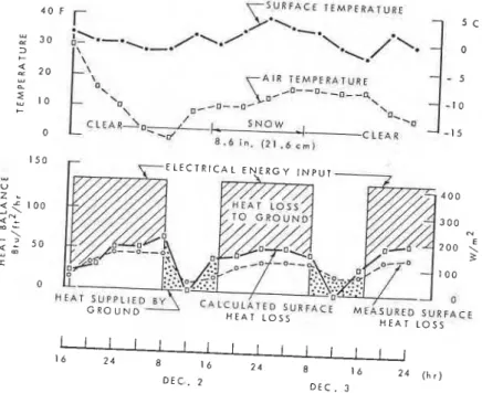
Figure 7 shows the estimated total ground heat l o s s f o r the s y s t e m a t s i t e D f o r one
period considered f a i r l y typical of l o s s e s that can o c c u r a t this s i t e . The e l e c t r i c a l energy used during the periods of operation w a s determined f r o m w a t t m e t e r s read a t r e g u l a r i n t e r v a l s . Surface heat l o s s was obtained i n two ways: f r o m m e a s u r e m e n t s of the heat flowmeter installed n e a r the s u r f a c e and f r o m calculations using the heat t r a n s f e r coefficients developed f o r a s h e l t e r e d s i t e . The difference between heat sup-
Figure 7 . Enirnatd ground h a loor for uninsulatd snow-melting sy- site D, ~ S U R F A C F T E M P E R A T U R E 4 0 F r- A I R T E M P E R A T U R E /Q--u- -m--& g r ~ D - - D C
-.
\ / .0 C L E A R J ~ _ r ! S N O W .! -a 0-'
i . 6 i n . C L E A R -15 0 1 . b c,,,l 150 u u z L < f l o o 2 u >2
50 1 u 0 0 H E A T L O S SFigure 8. Estimated ground heat loss for insulated mow-melting system, site A.
Y* E S ! L 3 "O
t
A I R T E M P E R A T U R E ,o--0--o\ 0"
0'-
l o i - q , , w , x ' I l l rr
1 1 1 , , , 0 8 2 4 E 16 I I J 2 4 F E B 4 F € B 3 E Irr F E E b--
7
31
plied and s u r f a c e heat l o s s r e p r e s e n t s t h e total ground h e a t l o s s o r gain. These r e s u l t s show that during t h e period when power w a s on, 50 percent o r m o r e of the electrical energy went to warming the s l a b and the ground surrounding it. During the day when the power w a s off, s o m e of the heat s t o r e d i n t h e s l a b and the ground became available
f o r maintaining operating t e m p e r a t u r e s . I
Figure 8 shows the estimated total ground heat l o s s a t s i t e A, with the s y s t e m op- I e r a t i n g u n d e r quite s e v e r e w e a t h e r conditions. The difference between e l e c t r i c a l en-
e r g y used and s u r f a c e heat l o s s (estimated by using t h e appropriate heat t r a n s f e r coef- ficients) was p r i m a r i l y edge l o s s plus heat l o s t o r gained by the s l a b when
it
underwent t e m p e r a t u r e change. Heat l o s s through the insulation under t h e s l a b was l e s s than 1I
p e r c e n t of the total h e a t l o s s .The r e s u l t s f r o m t h e two c a s e h i s t o r i e s i l l u s t r a t e the advantage of installing in- sulation under embedded snow-melting s y s t e m s . Not only is the l o s s to the ground r e - duced to a s m a l l amount (this w a s verified under a wide range of operating conditions), but also t h e heat s t o r e d i n the c o n c r e t e a p p e a r s to become m o r e readily available f o r maintaining operating t e m p e r a t u r e s . The technology of insulated roadways is now r e a -
I
Isonably well established (20) and could be applied to embedded snow-melting s y s t e m s . Use of insulation would p r ~ c t i c a l l y eliminate the heat l o s s downward to the ground under the s l a b and the need to make allowances f o r i t in design calculations.
CONCLUSIONS
1. The ASHRAE f o r m u l a s (3) f o r calculating design heat r e q u i r e m e n t s f o r snow- melting s y s t e m s a r e r e a s o n a b l y satisfactory, provided adjustments a r e made to take into account the s i z e of the heated a r e a , the exposure to wind, and the height a t which
.
I wind speeds a r e m e a s u r e d .2. The limiting condition controlling design heat r e q u i r e m e n t s of snow-melting s y s t e m s operating i n cold c l i m a t e s is the maintenance of a n ice-free surface imme- diately a f t e r s n o w s t o r m s r a t h e r than the effective melting of snow during a s t o r m .
i
These heat r e q u i r e m e n t s can be estimated by calculating the r a t e of s u r f a c e heat l o s s..
I f r o m b a r e , wet pavements and by using weather data obtained f r o m representative o rdesign s t o r m s .
3. The u s e of insulation reduces edge and ground h e a t l o s s e s to insignificant amounts and eliminates t h e need to make allowances f o r such l o s s e s i n design heat calculations f o r insulated snow-melting s y s t e m s .
ACKNOWLEDGMENTS
I a m indebted to s e v e r a l colleagues in the geotechnical section f o r help i n the p r e p a r a -
tion of this p a p e r and to A. Laberge f o r taking many of the field observations. This p a p e r i s a contribution f r o m the Division of Building R e s e a r c h , National Research Council of Canada, and is published with the approval of the d i r e c t o r of that division.
1
REFERENCESi
I 1. W. P. Chapman and S. Katunich. Heat Requirements of Snow Melting Systems. , T r a n s . , A m e r i c a n Society of Heating and Air-conditioning Engineers, Vol. 62,
1956, pp. 359-372.
2. P. J. Williamson. The Estimation of Heat Outputs f o r Road Heating Installations. Road R e s e a r c h Laboratory, Crowthorne, B e r k s h i r e , England, RRL Rept. LR 77, 1967.
3. ASHRAE Guide and Data Book-Systems. American Society of Heating, Refriger- ating, and Air-Conditioning Engineers, New York, 1970, chapter 36.
4. W. G. Potter. Electric Snow Melting Systems. Journal American Society of Heat- ing, Refrigerating, and Air-conditioning Engineers, Vol. 9, No. 10, 19 67, pp. 35-44.
* ---
-
- 1 II
i
A. E. Kobold and G. H. West. Snow Melting by E l e c t r i c a l Means. Ontario Hydro R e s e a r c h News, Vol. 12, No. 37, 1960, pp. 18-24.
J. D. George and C. S. Wiffen. Snow and Ice Removal From Road Surfaces by E l e c t r i c a l Heating. Highway Research Record 94, 1965, pp. 45-51.
M. Jakob and G. A. Hawkins. Elements of Heat Transfer. John Wiley and Sons,
New York, 3rd Ed., 1958.
R. G. Coulter and S. Herman. Control of Snow and Ice by Induced Melting. City
College R e s e a r c h Foundation, New York, 1964.
L. H. Watkins. Control of Road Snow and Ice by Salt and Electrical Road Heating.
HRB Special Rept. 115, 1970, pp. 146-156.
Building R e s e a r c h Station Digest-Wind Environment Around Tall Buildings. Building R e s e a r c h Station, Garston, Watford, England, Digest 141, May 1972.
W. C. Swinbank. Long-Wave Radiation F r o m Clear Skies. Journal, Royal
Meteorological Society, Vol. 89, 1963, p. 339.
M. I. Budyko. The Heat Balance of the E a r t h ' s Surface (N. A. Stephanova, tr.). U.S. Department of Commerce, 1956.
H. L. Penman. Evaporation: An Introductory Survey. Netherlands Journal of Agricultural Science, Vol. 4, No. 1, 1956.
G. E. Harbeck. Discussion of Evaporation Computations f o r P r a i r i e R e s e r v o i r s . P r o c . , Hydrology Symposiunl 2, National R e s e a r c h Council of Canada, 1961, p. 164.
I. S. Bowen. The Ratio of Heat Losses by Conduction and by Evaporation From Any Water S u r f a c e . Physical Review, Vol. 27, 1926, pp. 779-787.
G. P. Williams. Heat Requirements of Snow Melting Systems in Canada. Proc.,
National Conference on Snow and Ice Control, Roads and Transportation Association of Canada, Ottawa, April 1973.
R. V. Dexter. Nova Scotia's Record Snow S t o r m on 2-3 F e b r u a r y 1960. Weather-
wise, Vol. 13, No. 4, 1960, pp. 153-157.
P. A. S c h a e r e r . Melting Snow and Ice by Heating Pavements. Division of Building Research, National Research Council of Canada, Building Research Note 55, 1966. R. J o r g e n s e n and Associates. Non-Chemical Methods of Snow and I c e Control on Highway S t r u c t u r e s . NCHRP Rept. 4, 1964.
E. Penner, M. D. Oosterbaan, and R. W. Rodman. Performance of City Pave-
ment S t r u c t u r e s Containing Foamed Plastic Insulation. Highway Research Record 128, 1966, pp. 1-17.
![[PDF] Support pour Apprendre à créer des programmes avec Python | Formation informatique](data:image/gif;base64,R0lGODlhAQABAIAAAP///wAAACH5BAEAAAAALAAAAAABAAEAAAICRAEAOw==)