Publisher’s version / Version de l'éditeur:
Vous avez des questions? Nous pouvons vous aider. Pour communiquer directement avec un auteur, consultez la première page de la revue dans laquelle son article a été publié afin de trouver ses coordonnées. Si vous n’arrivez pas à les repérer, communiquez avec nous à PublicationsArchive-ArchivesPublications@nrc-cnrc.gc.ca.
Questions? Contact the NRC Publications Archive team at
PublicationsArchive-ArchivesPublications@nrc-cnrc.gc.ca. If you wish to email the authors directly, please see the first page of the publication for their contact information.
https://publications-cnrc.canada.ca/fra/droits
L’accès à ce site Web et l’utilisation de son contenu sont assujettis aux conditions présentées dans le site LISEZ CES CONDITIONS ATTENTIVEMENT AVANT D’UTILISER CE SITE WEB.
International Conference on Durability & Sustainability of FRP Composites for Construction and Rehabilitation (CDCC 2011): 20 July 2011, Quebec City, Quebec [Proceedings], pp. 151-158, 2011-07-20
READ THESE TERMS AND CONDITIONS CAREFULLY BEFORE USING THIS WEBSITE.
https://nrc-publications.canada.ca/eng/copyright
NRC Publications Archive Record / Notice des Archives des publications du CNRC :
https://nrc-publications.canada.ca/eng/view/object/?id=e6570eb4-19e0-4859-a321-87825f5ba943 https://publications-cnrc.canada.ca/fra/voir/objet/?id=e6570eb4-19e0-4859-a321-87825f5ba943
NRC Publications Archive
Archives des publications du CNRC
This publication could be one of several versions: author’s original, accepted manuscript or the publisher’s version. / La version de cette publication peut être l’une des suivantes : la version prépublication de l’auteur, la version acceptée du manuscrit ou la version de l’éditeur.
Access and use of this website and the material on it are subject to the Terms and Conditions set forth at
Fire testing of FRP strengthened reinforced concrete columns
Fire t e st ing of FRP st re ngt he ne d re inforc e d c onc re t e c olum ns
N R C C - 5 4 4 3 6
B é n i c h o u , N . ; C r e e , D . ; C h o w d h u r y , E . U . ; G r e e n , M . F . ; B i s b y , L . A .
A u g u s t 2 0 1 1
A version of this document is published in / Une version de ce document se trouve dans:
International Conference on Durability & Sustainability of FRP Composites for Construction and Rehabilitation (CDCC 2011), Quebec City, Quebec, July-20-22, 2011, pp. 151-158
http://www.nrc-cnrc.gc.ca/irc
The material in this document is covered by the provisions of the Copyright Act, by Canadian laws, policies, regulations and international agreements. Such provisions serve to identify the information source and, in specific instances, to prohibit reproduction of materials without written permission. For more information visit http://laws.justice.gc.ca/en/showtdm/cs/C-42
Les renseignements dans ce document sont protégés par la Loi sur le droit d'auteur, par les lois, les politiques et les règlements du Canada et des accords internationaux. Ces dispositions permettent d'identifier la source de l'information et, dans certains cas, d'interdire la copie de documents sans permission écrite. Pour obtenir de plus amples renseignements : http://lois.justice.gc.ca/fr/showtdm/cs/C-42
Fire testing of FRP strengthened reinforced concrete columns
N. Bénichou1, D. Cree2, E.U. Chowdhury2, M.F. Green2, and L.A. Bisby3
1
Institute for Research in Construction, National Research Council of Canada, Ottawa, Canada 2
Dept. of Civil Engineering, Queen’s University Kingston, Ontario, Canada 3
Institute for Infrastructure and Environment, University of Edinburgh, Scotland, UK
ABSTRACT
This paper presents the results of full-scale fire tests on two concrete columns strengthened with fibre reinforced polymer sheets and protected with a new insulation system. One column was circular while the other was square. The columns were subjected to the ULC-S101 standard fire. Both columns obtained fire endurance ratings of over 4 hours. At the end of the fire test, the columns were loaded to failure. The temperatures in the columns during the fire test and the load capacities of the columns will be presented. Additional work is required to compare the results against thermal and structural numerical models developed specifically for circular and square columns.
1. INTRODUCTION
Fibre reinforced polymers (FRPs) are now widely applied for repairing concrete structures [1,2]. FRP are known to have excellent strength, stiffness, and corrosion resistance, but their mechanical properties are significantly reduced at elevated temperatures due to the properties of the matrix resin. As such, concerns regarding fire resistance have limited FRP applications in buildings. To address this concern, a new fire insulation material is applied on the surface of FRP wraps to obtain appropriate fire resistance. Novel materials for potential use inside a building, including FRPs and insulation materials must pass certain fire exposure limits as prescribed in North America by CAN/ULC S101 [3] or ASTM E119 [4]. The objective is for the structure protected with the new insulation material to withstand a fire resistance (fire endurance) test by being exposed to a standard fire for a specific duration, under strict conditions. Until the fire endurance property of this unique supplemental insulating fire protection system is known, it will hinder its extensive use as a reinforcement coating on the interior of buildings.
1
2. MOTIVATION
To gain insightful information on fire endurance, there has been an on-going collaborative research program in the development of various insulating materials for protecting FRP wrapped reinforced concrete columns in fire conditions. The initial tests consisted of two circular columns (Column 1 and Column 2) [5], followed by another three circular columns (Column 3, Column 4 and Column 5) [6]. The current study reports the work done on one circular column (Column 5) [6] and one recently tested square column (Column 6). A team comprising of the National Research Council of Canada (NRC), Queen’s University, Canada and industry partner Sika Canada are collaborating on the current research project. This project involves the full-scale fire test of two concrete columns strengthened with FRP wrap and insulated with a supplemental fire protective coating. The column fabrication, FRP strengthening, the insulation fire protection material and fire test results are discussed.
The objectives for these fire tests are to investigate the behaviour of FRP strengthened reinforced concrete columns protected with an insulation layer and subjected to elevated temperatures. The strengthened and insulated columns were subjected to the ULC-S101 standard fire, under sustained service load, which simulates the load that the columns would be expected to experience in an actual fire situation. The results of both experiments (Columns 5 and 6) are presented in this paper.
3. EXPERIMENTAL PROCEDURE 3.1 Column Test Specimens
The experimental program consisted of two fire tests on one circular column and one square reinforced concrete column strengthened with the SikaWrap Hex 103C FRP externally-bonded strengthened system and insulated with Sikacrete®-213F, a spray-applied fire protection mortar. The columns were designated as Column 5 and Column 6, respectively and photos of the columns before fire testing are shown in Figure 1. Column 5 was 400 mm in diameter while the cross-section of Column 6 was 305 mm by 305 mm. Both columns had a height of 3810 mm and were designed for 28 MPa concrete strength using Type 10 Portland cement with crushed carbonate aggregate, maximum aggregate size of 14 mm, and natural sand as the fine aggregate. The longitudinal steel reinforcement in Column 5 consisted of eight 20M (19.5 mm diameter) deformed bars, symmetrically placed with 40 mm clear cover to the spiral reinforcement. The lateral reinforcement for the columns consisted of 10M (11.3 mm diameter) deformed steel spiral with a centre-to-centre pitch of 50 mm. The longitudinal reinforcing bars and the steel spiral had average yield strengths of 456 MPa and 396 MPa, respectively. The primary longitudinal reinforcement bars for Column 6 were four 25M deformed steel bars. The lateral reinforcement for the column consisted of 10M deformed steel bars spaced at 305 mm. The main reinforcing bars and ties all had average yield strengths of 477 MPa. The steel reinforcement had a clear cover of 40 mm from the exterior surface of the concrete to the steel ties and a 50 mm concrete cover to the principal reinforcement. Column 5 was poured vertically into a 400 mm inside-diameter Sonotube™, while Column 6 was cast vertically in a plywood formwork. The columns were instrumented with Chromel-alumel (Type-K) thermocouples to record the internal
2
temperatures within the concrete, the reinforcing steel bars, the concrete-FRP interface, the FRP-insulation interface and the outer surface of the FRP-insulation.
3.2 FRP Strengthening and Fire Protection
Both columns were strengthened with a SikaWrap Hex 103C unidirectional carbon/epoxy FRP strengthening system with a Sikadur 300 resin epoxy saturant/adhesive. Column 5 was strengthened with two layers of FRP wrap while Column 6 was strengthened with three layers. The carbon FRP has an ultimate tensile strength of 849 MPa and tensile elastic modulus of 70.5 GPa. To provide fire protection, Sikacrete®-213F, a supplemental fire insulation material, was spray-applied over the surface of the FRP wrapped columns. Prior to the spray application for Column 5, a 1/8 th inch diameter steel mesh, having 50 mm by 50 mm openings, was attached to the surface of the column to provide reinforcement for the protection system. Column 5 had an average insulation thickness of 44 mm, while Column 6 had an average insulation thickness on flat surfaces of 40 mm and an average corner insulation thickness of 51 mm.
3.3 Fire Endurance Test
The fire endurance experiments were conducted by exposing the columns to heat in a furnace specially built for fire testing loaded columns. The columns were installed in the furnace by bolting the end plates to the test frame loading head at the top and a hydraulic jack at the bottom. This resulted in a fixed-fixed end condition for the column, which simulates the end conditions to be expected in an actual building. Column 5 was loaded in compression until the applied load on the circular column was 3031 kN, and Column 6 until the applied load on the square column was 1717 kN. The respective loads were maintained at a constant value throughout the fire endurance test. Both columns did not fail under their respective sustained service loads, therefore after 4 hours of fire exposure; the loads were increased until failure was observed.
(a) (b)
Fig. 1. Images of the FRP-wrapped and insulated concrete columns (a) circular and (b) square, prior to fire test.
3
4. Results and Discussion 4.1 Temperature Behaviour
The fire behaviour of the insulation, FRP wrap, and crack propagation in the insulation in Column 5 and Column 6 were monitored during the test through small observation windows (view ports) in the walls of the furnace. Prior to commencing the fire tests, it was observed on both columns that minor cracks developed on the surface of the dried insulation, which were due to shrinkage. The initial cracks were approximately less than 5 mm wide but widened to about 10 mm as the test progressed. For both columns, flames were seen emanating through the small cracks on the surface of the insulation at approximately 2 hours into the fire test. Cracks on the surface of the insulation, prior and during the fire endurance test, are depicted in Figure 2. The steel mesh reinforcement within the insulation of Column 5 may have prevented the spalling of the insulation from the column surface, however, no spalling of the insulation system was observed from Column 6 which did not contain a mesh. Prior to the column failures, the fire protection insulation system remained intact with minor external cracks throughout the length of the column for the duration of the fire test.
The temperature results for Column 5 and Column 6 at mid-height for horizontally positioned thermocouples are given in Figure 3 and Figure 4, respectively. The temperature measurement readings are for the insulation surface, FRP surface, concrete surface and internal to the concrete. Both Figures 3 and 4 also include the standard fire curve. During the test on Column 5, a dip in the average furnace temperature was a result of an abrupt furnace stop at 3 hours into the fire test and required 12 minutes to bring the temperature inside the chamber back to the prescribed temperature-time curve.
(a) (b)
Fig. 2. (a) Typical cracks on the surface of the fire insulation system prior to the fire test, and (b) flame from the cracks on the surface of the fire insulation system during the fire test.
4
0 200 400 600 800 1000 -1 0 1 2 3 4 5 6 Temperature (°C)
ASTM E-119 Insulation surface Concrete surface corner FRP surface ASTM E-119 Insulation surface
Concrete surface Cover 63 mm FRP surface Concrete surface
Cover 153 mm Cover 50 mm Cover 150 mm 0 200 400 600 800 1000 -1 0 1 2 3 4 5 6 Temperature (°C) Time (hours) Time (hours)
Fig. 3. Column 5 temperature of thermocouples Fig. 4. Column 6 temperature of thermocouples at at mid-height as a function of time. mid-height as a function of time.
The polymer resin (Sikadur 300) has a glass transition temperature (Tg) of 60°C if cured at
ambient temperature. The concrete surface temperature for Column 5 (Figure 3) was shown to have an average temperature of 60.5°C after 29 minutes of fire exposure. This demonstrated that the insulation system limited the time at which the temperature was below the Tg of the polymer
resin, which is important for the bond performance. The temperatures recorded at the concrete surface increased at a steady rate until they reached a plateau at 100°C. This plateau is due to moisture evaporation within the insulation. After approximately 1 h 30 min, the concrete surface temperature began to increase at a higher rate up to 266°C after 4 hours. The temperature at the concrete surface remained below the manufacturer stated Tg for about 29 minutes, by providing a thickness of approximately 44 mm of insulation. After 4 hours, the highest temperatures recorded at the FRP surface and concrete surface were 408°C and 266°C, respectively.
Column 6 had an average concrete surface temperature of 60.1°C (Figure 4) after 33 minutes of fire exposure. Similarly, the corner thermocouples at mid-height detected an average concrete surface corner temperature of 60.2°C (Figure 4) after 22 minutes of fire exposure. This showed that the corner FRP increased in temperature quicker than the sides. The data demonstrated that it is possible to maintain the temperature of the concrete surface below the Tg of the FRP material
for about 0.5 hrs by providing an insulation system of approximately 40 mm thick. After 4 hours, the highest temperatures recorded from the horizontally positioned thermocouples at the FRP surface and concrete surface were 406°C and 250°C, respectively.
For both columns, the test data indicated the insulation system would be unable to maintain the FRP temperature below the Tg of the polymer resin for prolonged periods of time during fire.
However, the insulation system was able to maintain the temperatures within the concrete and reinforcing steel below 200°C. For example, Figure 3 shows that after 4 hours, the temperatures in Column 5 on the concrete surface, in the concrete at 50 mm from surface (at the location of the reinforcement), and in the concrete at 150 mm from surface are 266°C, 148°C and 98°C, respectively. Similarly, Figure 4 shows that, for Column 6 after 4 hours, the concrete surface, the
5
reinforcement temperatures, the concrete at 63 mm from the surface, and concrete at 153 mm from the surface are 250°C, 193°C 164°C and 136°C, respectively. The insulation system was able to maintain the temperatures within the concrete and reinforcing steel of both columns below 200°C. By maintaining this criteria, no significant deterioration in the mechanical properties of concrete and steel occurred. Hence, it can be stated that the columns maintained their full unconfined axial load carrying capacity for greater than 4 hours of exposure to the ASTM E119 standard fire.
4.2 Structural Behaviour
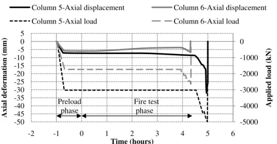
Figure 5 shows the axial deformations and load applied as a function of time for Columns 5 and 6 during the preload and fire test phase. A negative axial deformation or applied load value indicates compression of the column. The columns experienced an initial load of approximately 350 kN due to the weight of the hydraulic jack prior to the start of the preload phase. Column 5 resisted the sustained concentric load of 3054 kN for 4.5 hours. Therefore, after 4.5 hours, the load was steadily increased until the column reached failure at a load of 4984 kN. The column failed by apparent crushing of the concrete core. Similarly, Column 6 resisted the sustained fire load of 1717 kN for 4 hours. Since it did not fail, the load level was increased to 2641 kN, at which point the column failed in a non-violent fashion by crushing of the concrete core, which resulted in the insulation delaminating at the centre of the column, while the insulation remained largely intact at the extremities of the column. The temperature data obtained during the fire endurance test of Column 5 and Column 6 show that the FRP wrap had been rendered ineffective even with an insulation layer due to increased temperatures in excess of its glass transition temperature. However, due to the superior thermal insulation system, the concrete and reinforcing steel retained their room-temperature strength.
Column 5-Axial displacement Column 6-Axial displacement
Column 5-Axial load Column 6-Axial load
-5000 -4000 -3000 -2000 -1000 0 -50 -45 -40 -35 -30 -25 -20 -15 -10 -5 0 5 -2 -1 0 1 2 3 4 5 6 Applied load (kN) Axial deformation (mm) Time (hours) Preload phase Fire test phase
Fig. 5. Applied load and axial deformation as a function of time for Columns 5 and 6.
6
The axial deformations of the columns were the result of a combination of load effects and thermal expansion. During the preload phase of the fire test, Column 5 had an initial 7.3 mm axial deformation due to the applied value of 3054 kN. After the preload phase, the axial load (3054 kN) was kept constant for 4.5 hours of fire exposure. No major expansion was observed during heating up to 4.5 hours due to the relatively low temperatures in the concrete. For instance, after 3 hours of fire exposure, the temperature of the rebar for Column 5 was 105°C and the concrete surface temperature was 225°C. However, a severe drop in axial deformation after 4.5 hours occurred from the increasing applied load up to failure. At failure, Column 5 had an axial deformation of 32 mm.
Similarly, during the preload phase of the fire test, Column 6 had a 6 mm axial deformation as a result of the applied load of 1717 kN. After the preload phase, the applied axial load (1717 kN) was kept constant for 4 hours of fire exposure. After 1 hour of fire exposure, the column began to experience a gradual expansion of approximately 2 mm for up to 3 hours or until the end of the test. The source of expansion in Column 6 may be from the thermal expansion of the concrete and a lack of spiral reinforcement as contained in Column 5. For instance, the temperature of the rebar for Column 6 was 150°C and the concrete surface temperature was 200°C after 3 hours. The drop in the deformation curve after 4 hours was due to the increase in applied load to failure. Column 6 experienced a final axial deformation of 6.8 mm. In general, the initial degradation for the compressive strength of concrete is experienced between 200 and 250°C, while at 300°C strength reduction is in the range of 15-40%. [7]. In addition, the thermal expansion of concrete is reduced when a compressive strength of 0.45f’c or higher is applied to the specimen during
heating [8]. Based on the strength of Column 6 concrete, (36 MPa at 28 days, but tested after one year) applied load and cross-sectional area, a small expansion from the concrete may have occurred. The temperatures in the steel reinforcement remained low enough to prevent any material property degradation. Normally, at 350°C or higher, the yield strength of conventional steel is reduced by 66% of its room temperature yield strength [9]. According to the temperature of the reinforcement in both columns, the ductility did not increase nor did the yield strength and ultimate tensile strength reduce.
5. CONCLUSIONS
From results of these full-scale fire endurance tests on one circular and one square FRP wrapped
reinforced concrete column, the following conclusions can be drawn:
1. The insulation system was effective in protecting the FRP wrapped columns such that they were able to achieve four hour fire endurance ratings according to ULC S101 and ASTM E119. 2. The insulation fire protection material was not able to maintain the temperature of the FRP below its glass transition temperature for the duration of the fire endurance test. With an average insulation thickness of 44 mm, the temperature of the concrete surface for Column 5 reached its glass transition temperature of 60°C at about 29 minutes into the fire test, while Column 6 with 40 mm of insulation material had an FRP temperature of 60°C at 33 minutes into the fire exposure. The difference may be partially attributed to the mechanism of heat transfer through the insulation in a circular column versus a rectangular column.
7
8
3. The supplementary insulation fire protection material used in this fire endurance test is an effective fire protection system. However, the shrinkage cracks in the cured insulation material should be investigated to further improve the system. Although flames were observed emanating from cracks formed in the insulation of both columns, the overall insulation remained intact for more than 4 hours of exposure to the ULC S101 or ASTM E119 standard fire.
6. REFERENCES
1. Neale, K.W., ‘FRPs for structural rehabilitation: A survey of recent progress’, Progress in
Structural Engineering and Materials, 2, 2000, 133-138.
2. Hollaway L.C., ‘A review of the present and future utilisation of FRP composites in the civil infrastructure with reference to their important in-service properties’, Construction and Building
Materials, 24, 2010, 2419-2445.
3. ULC. ‘Standard Methods of Fire Endurance Tests of Building Construction and Materials’ CAN/ULC-S101-07, Underwriters’ Laboratories of Canada, Scarborough, ON, 2007, 70 pp. 4. ASTM, Test Method E119-10b, ‘Standard Methods of Fire Test of Building Construction and Materials’ American Society for Testing and Materials, West Conshohocken, PA, USA, 2010, 33 pp.
5. Bisby, L.A., Kodur, V.R., and Green, M.F., ‘Fire endurance of fiber-reinforced polymer-confined concrete columns’, ACI Structural Journal, 102 (6), 2005, 883-891.
6. Chowdhury, Ershad 2009. Behaviour of fibre reinforced polymer confined reinforced concrete column under fire condition. PhD thesis, Department of Civil Engineering Queen’s University, Kingston, Ontario, Canada.
7. Georgali, B., and Tsakiridis, P.E., ‘Microstructure of fire-damaged concrete-a case study’,
Cement & Concrete Composites, 27, 2005, 255-259.
8. Thelandersson, S. ‘On the multiaxial behaviour of concrete exposed to high temperature’,
Nuclear Engineer Design, 75, 1982, 271-282.
9. Chijiiwa, R., Tamehiro, H., Funato, K., Yoshida, Y., Horii, Y., and Uemori, R., ‘Development and Practical Application of Fire-Resistant Steel for Buildings’, Nippon Steel Technical Report