Design and Control of
Supernumerary Robotic Limbs
by
Federico Parietti
B.S., Polytechnic University of Milan (2008)
W
S.M., Polytechnic University of Milan (2011)
Submitted to the Department of Mechanical Engineering
in partial fulfillment of the requirements for the degree of
Doctor of Philosophy in Mechanical Engineering
at the
MASSACHUSETTS INSTITUTE OF TECHNOLOGY
September 2016
@
Massachusetts Institute of Technology 2016. All rights reserved.
A uthor ...
C ertified by ...
Signature redacted
Department of Mechanical Engineering
August 15, 2016
Signature redacted
VH. Harry Asada
Ford Professor of Mechanical Engineering
Thesis Supervisor
Signature redacted
A ccep ted b y ...- -- -- -- -- -- -- -- --
--Rohan Abeyaratne Chairman, Department Committee on Graduate Theses
M FTE H N O
[SEP
13 2016
Design and Control of
Supernumerary Robotic Limbs
by
Federico Parietti
Submitted to the Department of Mechanical Engineering on August 15, 2016, in partial fulfillment of the
requirements for the degree of
Doctor of Philosophy in Mechanical Engineering
Abstract
Humans possess the remarkable ability to control their four natural limbs in a volun-tary, accurate and independent manner. The simultaneous use of two or more limbs allows humans to learn and robustly perform a wide range of complex tasks. Since the use of multiple limbs enables humans to master advanced motor skills, it would be interesting to study whether having additional limbs would enable users to expand their skill set beyond its natural limits. Inspired by this vision, we propose a new form of human augmentation: a wearable robot that augments its user by providing him with an additional set of robotic limbs. We named this new device Supernumerary Robotic Limbs (SRL). However, humans have never had the possibility to control ad-ditional, powered limbs besides their natural arms and legs. The main theme of this thesis, besides realizing a prototype of the robot and proving its usefulness in real-world tasks, is demonstrating that humans can voluntarily control additional limbs as if they were a part of their own body.
We realized a lightweight (3.5 kg), comfortable prototype of the SRL that can be easily worn by an unassisted user. Two robotic limbs can assist the user in both manufacturing and locomotion tasks. We created control strategies that take ad-vantage of the independence of the robotic limbs, enabling them to provide optimal assistance in specific tasks such as weight support, body stabilization, using powered tools, sitting/standing and dynamic walking. Finally, we developed an EMG-based control interface that enables users to voluntarily control the motion of the robotic limbs, without interfering with the posture of the rest of the body. The new augmen-tation technology presented in this thesis opens up new possibilities in the field of wearable robotics. The voluntary control of additional robotic limbs falls within the range of motor skills that humans can learn, and enables the acquisition of a new set of complex skills that would not be achievable using only the natural body.
Thesis Supervisor: H. Harry Asada
Title: Ford Professor of Mechanical Engineering
Acknowledgments
I would like to thank all of the people who, directly or indirectly, helped me during
my doctoral studies. First, I would like to thank Prof. Asada for giving me the opportunity to work on this unique robotics project. Not many advisors have the courage and the vision to pursue research directions that are completely new and original, like this one. Prof. Asada has allowed and enabled me to implement my vision for this thesis, and there is no better thing than working on what you love and believe in.
I would like to thank MIT for giving me the opportunity of pursuing my highest
degree. Studying here has always been a dream for me, and I have never nor will ever take it for granted. I still can't believe that I got in, and I hope that I worked hard
enough to show everybody - including myself - that I deserved this opportunity.
I would like to thank all of the professors and teaching assistants in the classes that I took here at MIT. The challenges you gave me were always interesting and exciting to solve. From the problem sets to the tests to the Qualifying Exams, it has been a pleasure to fight through every question to prove that I got it. This level of challenge is exactly what I was expecting from an MIT education.
I would like to thank the members of my thesis committee for their support and
advice during my doctoral studies. Together with Prof. Asada, they are the faculty members that I admire the most, and it has been a true honor to work with them on this research endeavor. In particular, I would like to thank Prof. Hogan for sharing his knowledge on the neural mechanisms at the base of the control of motion, Prof. Herr for his inspiring vision about the future of human augmentation, and Prof. Geyer for being an exceptional graduate research mentor and for believing in my research before anyone else.
I would like to thank my labmates, from the UROP students to the grad students,
from the postdocs to the visiting engineers from Japan, for their incredible support in these years. You made this thesis possible not only with your knowledge and your advice, but also with your constant encouragement. And you also reminded me to
sleep and to go home from time to time, which I tend to forget too often. Your names are too many to be named here, but you already know that you are forever invited at all of my rooftop parties.
I would like to thank my friends in Cambridge and all over the world. Thank
you for always being patient and supportive even if I disappeared from any form of communication for weeks at times, when I was working on a new prototype or experiment. I really appreciate what you did for me, and the fact that you always believed in me even if sometimes I didn't do it myself. I would also like to thank my girlfriend for understanding and supporting my vision, even when pursuing it meant working for insane amounts of time in the lab. Thank you for making the time we spend together always special, and for supporting my goals to the point of amplifying them.
I would like to thank my family for teaching me the value of education, and for
supporting me in the darkest moments. I always knew that you had my back, even when you were in a different continent. And I know that I have been extremely privileged to be raised in an environment where I always had the luxury of putting my personal goals first, without worrying about anything else.
Finally, I would like to reserve special thanks to all of those who doubted me, or questioned my determination and my objectives. Thank you for providing additional motivation, and moral fuel to keep me awake during the long nights in the lab. I am proud of proving that you were wrong, with this document. And I cannot wait to continue the relentless pursuit of my goals. Enjoy the show, because there's much more to come!
Contents
1 Introduction 17
2 Voluntary, Independent Control of Extra Limbs 21
2.1 Introduction . . . . 21
2.2 Experimental setup and control strategy . . . . 23
2.3 H ypotheses . . . . 27
2.4 Experim ents . . . . 27
2.5 D iscussion . . . . 31
2.6 C onclusions . . . . 35
3 Design 37 3.1 Overview of the robot . . . . 37
3.2 Harness and base . . . . 41
3.3 Spherical load-bearing joints . . . . 44
3.4 Pneum atic legs . . . . 49
3.5 End effectors . . . . 52
4 State Estimation 55 4.1 Introduction . . . . 55
4.2 Using additional limbs to assist aircraft assembly tasks . . . . 56
4.3 Robot design: the first SRL prototype . . . . 58
4.4 Dynamic models . . . . 59
4.4.1 Equations of Motion of the Wearable Robotic System . . . . . 59 7
4.4.2 Human Disturbances Model . . . .
4.5 K alm an filtering . . . .
4.5.1 Basic model of SRL and human-induced disturbances . . .
4.5.2 Effect of sensors choice on state estimation . . . . 4.5.3 Effect of robot configuration on state estimation . . . .
4.5.4 Effect of bracing on state estimation . . . .
4.5.5 Estimation of disturbances by using the augmented model
4.6 Bracing strategy . . . .
4.7 C onclusions . . . .
5 Bracing Strategy: 2D Analysis
5.1 Introduction . . . .
5.2 Robot design: the second SRL prototype
5.3 Bracing and load bearing analysis . . . .
5.3.1 The Bracing Strategy . . . .
5.3.2 Load Bearing Analysis . . . . 5.4 Optimization . . . . 5.4.1 Introduction . . . . 5.4.2 Problem Statement . . . . 5.4.3 Optimization . . . . 5.5 Discussion . . . . 5.5.1 Comparison . . . .
5.5.2 Bracing With Two Robotic Arms
5.6 Conclusions . . . .
6 Combining Bracing and Task Assistance 6.1 Introduction . . . . 6.2 Applying the SRL to aircraft fuselage assembly 6.3 Drill jig anchoring strategies . . . .
6.3.1 Basic Strategy . . . . 6.3.2 Leaning Strategy . . . . 8 62 63 64 65 67 68 69 71 73 75 . . . . 7 5 . . . . 7 6 . . . . 7 8 . . . . 7 8 . . . . 8 0 . . . . 8 3 . . . . 8 3 . . . . 8 4 . . . . 8 5 . . . . 88 . . . . 88 . . . . 90 . . . . 90 93 . . . . 93 94 96 98 99
6.3.3 General Strategy . . . . 100
6.4 Optimization . . . . 103
6.5 Discussion . . . . 106
6.6 Conclusions . . . . 108
7 Bracing Strategy: 3D Analysis 111 7.1 Introduction . . . 111
7.2 Design Concept . . . . 112
7.2.1 Motivation for the use of a prismatic joint . . . . 112
7.2.2 Potential Uses . . . . 112
7.2.3 Design and Control Issues . . . . 113
7.3 Support Stability . . . . 115
7.3.1 Basic Formulation . . . . 115
7.3.2 Stability Analysis . . . . 119
7.3.3 Stabilization . . . . 121
7.3.4 A Special Case . . . . 123
7.4 Implementation and Experiment . . . . 126
7.4.1 Prototype . . . . 126 7.4.2 Numerical Computation . . . . 127 7.4.3 Experimental Evaluation . . . . 133 7.5 Conclusion . . . . 137 8 Sitting/Standing Assistance 139 8.1 Introduction . . . . 139 8.2 Technical Approach . . . . 139
8.3 Computing the assistive force during sitting/standing motions . . . . 142
8.4 Conclusions . . . . 144
9 Balance Augmentation 147 9.1 Introduction . . . . 147
9.2 Balance augmentation using extra limbs . . . . 147
9.3 Static balance assistance . . . . 9.3.1 System model . . . .
9.3.2 Standing support optimization 9.4 Gait sequences optimization . . . . .
9.4.1 4-2 Gait . . . . 9.4.2 3-3 Gait . . . . 9.5 Implementation . . . .
9.5.1 Space and time scaling . . 9.5.2 Experimental results . . . . . 9.6 Conclusions . . . . 10 Conclusions 10.1 Robot design . . . . 10.2 Task-oriented assistance . . . . 10.3 Voluntary control . . . .
10.4 Future research directions . . . .
. . . . 150 . . . . 150 . . . 152 . . . 153 . . . . 155 . . . . 160 . . . . 164 . . . . 164 . . . . 165 . . . . 166 167 . . . . 167 . . . . 169 . . . . 171 . . . 173 10
List of Figures
1-1 Vision for the Supernumerary Robotic Limbs (SRL) as an assistive device 18 1-2 The SRL can assist the locomotion of patients that today are forced
to use simple passive tools . . . . 19
2-1 Subjects wearing the SRL and phases of the experiment . . . . 24 2-2 Control interface allowing the subjects to govern the motion of the
robotic limbs, and sensors employed during the experiment . . . . 25 2-3 Examples of the tracking performance of the subjects during the
ex-perim ent . . . . 29
2-4 Correlation between the trajectories of the targets and the motion of lim bs and torso . . . . 30 2-5 Average time to reach the targets in all of the phases of the experiment 31 2-6 Main combinations of muscles activated during the different phases of
the experim ent . . . . 33 2-7 Normalized tracking performance in the different phases of the
exper-im ent . . . . 34
3-1 Concept of the Supernumerary Robotic Limbs (SRL) . . . . 39
3-2 Main components of the Supernumerary Robotic Limbs (SRL) . . . . 40
3-3 The SRL is worn through a custom harness . . . . 42 3-4 Comparison of the SRL harness with state-of-the-art exoskeletons . . 43
3-5 The structure of the SRL, realized with composite materials . . . . . 45
3-6 Design of the ball and socket joint at the base of the robotic limbs . . 46
3-7 Implementation of the ball and socket joint at the base of the robotic
lim bs . . . . 47
3-8 Structure of a robotic limb . . . . 50
3-9 End effectors developed for the SRL . . . . 53
4-1 Supernumerary Robotic Limbs (SRL): first prototype . . . . 57
4-2 Dynamic model representing the user-SRL system . . . . 60
4-3 Sensor choice, based on error covariance . . . . 67
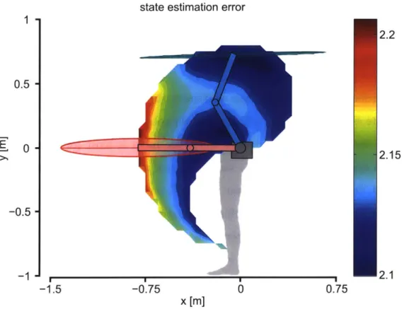
4-4 Mean squared error of a posteriori state estimation in the workspace of the SRL arm . . . . 68
4-5 Mean squared error of a posteriori state estimation in horizontal brac-ing and vertical bracbrac-ing . . . . 69
4-6 Mean squared error of a posteriori state estimation in the workspace of the SRL arm (augmented model). . . . . 70
4-7 Optimal SRL bracing configuration . . . . 74
5-1 The second SRL prototype . . . . 76
5-2 The model used to study the bracing strategy . . . . 80
5-3 Optimal bracing configurations . . . . 83
5-4 Finding the optimal SRL configuration with limited contact points . . 85
5-5 Experimental setup used to measure the power consumption of the SRL 89 5-6 Bracing with two robotic arms . . . . 91
6-1 The SRL prototype used to assist workers in a drilling task . . . . 94
6-2 Kinematic scheme of the SRL during the drilling task, applying the G eneral Strategy ... . . . . 97
6-3 Kinematic scheme of the SRL during the drilling task, applying the B asic Strategy . . . . 99
6-4 Kinematic scheme of the SRL during the drilling task, applying the Leaning Strategy . . . . 101
6-5 Optimal Ec for every contact point within the robot workspace . . . 102
6-6 Application of the assistive strategy to a manufacturing environment
with limited contact points . . . . 104
6-7 Visualization of the ground reaction forces and human hip forces in the two optimal configurations . . . . 107
7-1 Third prototype of the Supernumerary Robotic Limbs (SRL) . . . . . 112
7-2 Potential uses of the SRL . . . . 113
7-3 Schematic of the SRL system, coordinate frames, and joint angles 116 7-4 Forces and moments acting on the SRL system. . . . . 118
7-5 Symmetric equilibrium configuration. . . . . 124
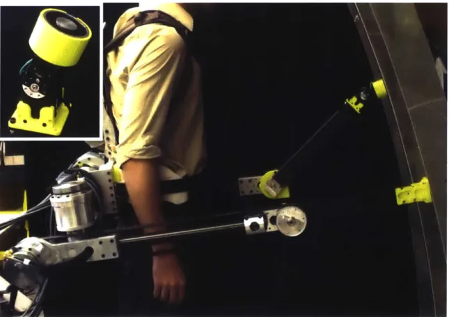
7-6 Prototype of SRL system worn by a human around the waist. . . . . 127
7-7 Eigenvalues of Support Stiffness Matrix Kp without stabilization control128 7-8 Deformation mode shapes obtained from the eigenvectors of the sup-port stiffness matrix Kp . . . . 129
7-9 Eigenvalues of Support Stiffness Matrix Kp in the range space . . . . 131
7-10 Eigenvalues of support stiffness matrix with full stabilization control 132 7-11 Effectiveness of combined null space stabilization and joint servo stiff-ness compared to joint servo alone . . . . 133
7-12 Computations for 3D SRL configurations . . . . 134
7-13 Experimental setup for stiffness tests. . . . . 135
7-14 Experimental results of stiffness tests . . . . 136
7-15 Typical application of body support with SRL system. . . . . 137
8-1 Wearing the latest SRL prototype . . . . 140
8-2 Model of the human-robot system, with length and angle parameters. 140 8-3 Position and torque at the leg joints during sitting/standing motions in the sagittal plane . . . . 142
8-4 Optimization of the assistive force provided by the SRL . . . . 143
8-5 Real-time computation of the assistive force . . . . 144
9-1 The human-SRL model for static balance assistance . . . . 151 13
9-2 The support polygon area in the static configuration as a function of
the dmax, L, and aL . . . . . . . . .. . . . . .. 154
9-3 Structure of the 4-2 walking gait . . . 155
9-4 Scheme of the SRL taking a new step during the 4-2 gait. . . . . 155
9-5 The support polygon area in walking gaits 4-2 and 3-3 as a function of dmax and aL . . . . . . . ... . . .. . .. . . . . .157
9-6 The support polygon area in walking gaits 4-2 and 3-3 as a function of L, and aL ... ... ...158
9-7 Structure of the 3-3 walking gait . . . 160
9-8 Scheme of the SRL taking a new step during the 3-3 gait. . . . . 161
9-9 Example performance of the step detection algorithm . . . . 165
List of Tables
5.1 Human workload comparison. . . . . 88
6.1 Variables of the problem . . . . 98
6.2 Optimal SRL configurations . . . . 106
6.3 Optimal SRL joint torques . . . . 108
7.1 Eigenvalues and eigenvectors of support stiffness matrix without sta-bilization control at 02= 145 . . . . 129
Chapter 1
Introduction
The Supernumerary Robotic Limbs (SRL) is a novel kind of wearable robot. It augments the user by providing two additional robotic limbs, which can move inde-pendently from the natural human limbs. The SRL is worn through a harness, and the robotic limbs are attached to a rigid base that follows the shape of the user's hip. The workspace of the robotic limbs has been designed to allow them to act both as legs (reaching the ground) and as arms (reaching the space in front and above the user). They can also reach areas outside of the workspace of the human limbs (e.g. behind the user). The innovative features of the SRL are suitable for a wide range of applications. Many areas of human activity could benefit from the use of additional limbs, from manufacturing to rehabilitation. The challenge associated with the SRL is that humans are not used to have more than four limbs. They frequently learn to use tools of various complexity, but these tools always clearly separated from their body. The main research question, which will be explored in this doctoral thesis, is how to intuitively and effectively control the Supernumerary Robotic Limbs as if they were a part of the user's body.
One promising field of application for the SRL is the manufacturing of large size, high added-value products, such as planes and ships. These activities require human workers to perform extremely complicated and fatiguing tasks, such as assembling electromechanical systems, drilling holes, inspecting structures. Additionally, workers might also be required to operate on elevated platforms or on scaffolds, which expose
0 0
Figure 1-1: Vision for the Supernumerary Robotic Limbs (SRL) as an assistive device for the elderly. The SRL is a wearable robot that extends its user's body with two additional robotic limbs. In this case, the robot is worn above normal clothing and assists the users when walking or sitting down and standing up.
them to the risk of slipping or falling down 1121. If we also consider that specialized
workforce has been rapidly aging - the median age in aircraft manufacturing is 48
years - there is a clear opportunity for the use of the SRL as an assistive tool to reduce fatigue and increase safety 1581. The buikling construction industry presents a similar opportunity, being the area of manufacturing with the most injuries caused
by falls 11, 63].
Another area in which the SR L would be useful is mobility assistance for the
elderly (Figure 1). The risk of losing balance and falling down is very high for the
18 f
I
K
Ii-/K
1>
/
I/
~lif,
A,
population over 80 years old [83], and this demographic is in continuous growth in developed countries 1161. Loss of mobility for the elderly also includes difficulties in safely sitting down or standing up [59]. The conventional tools used to address these problems present significant limitations, and are not suitable for the active lifestyle that senior citizens expect in modern societies (Figure 2). Canes and crutches require the use of one or both arms to be operated, and significant forces must be exerted in order to avoid slips. Walkers are easier to operate but their wheels limit them to flat surfaces, mostly inside buildings. The SRL could be used in this context as an assistive tool that provides balance aid and weight compensation while keeping the user's arms free. The robotic limbs could also assist elderly subjects when sitting down or standing up 138], or as an emergency help in case of slips. Being wearable and not based on wheels, the SRL is able to follow and help users in any situations, including stairs and irregular terrain (streets, parks, etc.). Figure 2 shows how the use of the SRL could address the needs of large numbers of patients who currently can only use simple passive tools for locomotor assistance.
Finally, the field of rehabilitation robotics represents a new and promising research
mobility O W
fully healthy temporary disability light disability severe disability paralyzed
no need for assistance traditional passive tools
current exoskeletons
extra legs extra legs +
exoskeleton
Figure 1-2: The SRL can assist the locomotion of patients that today are forced to use simple passive tools. The figure shows that current wearable robots (exoskeleton, orthoses) can assist only the most severe forms of locomotor impairment. It can also be observed that the combined use of SRL and exoskeletons could simultaneously assist locomotion and free the upper part of the body from the need of using crutches.
direction for the SRL. There is a large number of patients who need mobility assistance as a consequence of leg or spinal cord fractures, walking disabilities or neurological conditions such as strokes, Alzheimer's disease and Parkinson's disease [39, 81, 2J. Existing state-of-the-art wearable exoskeletons can provide these patients with the ability to stand and walk along a nominal gain cycle in the sagittal plane [32, 9,
23, 43, 54]. However, they do not have enough degrees of freedom to assist turning
and balance. As a result, they can benefit only subjects who are fit enough to use crutches. The SRL can be used to assist these patients without requiring any arm effort, and leaving their legs free to move and exercise. Moreover, the SRL could provide targeted support along the walking gait, helping the user only when needed or generating forces to correct gait abnormalities.
Together with a wide range of practical applications, the SRL also offers a unique opportunity to study how the neuromuscular control system can adapt to additional limbs, and learn to use them as if they were natural. The ultimate goal of this project is for the SRL to become a natural extension of the human body. In order to achieve this goal, suitable control signals must be identified, measured and robustly employed in the robot control system. These signals must be independent from the motion of the natural limbs, and able to accurately control the motion of the robotic limbs. Since humans are not naturally provided with more than four limbs, training protocols must be developed in order to rapidly and effectively teach this new motor skill to SRL users.
Chapter 2
Voluntary, Independent Control of
Extra Limbs
2.1
Introduction
Land-living vertebrates are capable of performing with apparent ease extremely com-plicated locomotion and manipulation tasks - ranging from flying to digging, from moving objects to modifying the surrounding environment. The simultaneous, coor-dinated use of multiple limbs is essential to perform such advanced behaviors. These tasks cannot be completed with a sequence of separate actions performed one after the other by a single limb. In animals with particularly evolved neuromuscular con-trol systems - such as mammalians - the ability to simultaneously and voluntarily control independent limbs enables the acquisition of new, complex motor skills. This is particularly evident in humans, who can learn a vast array of coordinated skills that far exceed the capabilities of a single limb. Examples of advanced tasks involving two or more limbs include playing musical instruments, practicing sports, and executing complex locomotion patterns (e.g. climbing, swimming). Natural limbs are the result of evolution, and for humans - like in all tetrapods - their number is limited to four. This limits the complexity of the coordinated tasks that humans can perform. The ability to control additional limbs together with the natural ones would open up new possibilities, enabling the learning and execution of more advanced locomotion and
manipulation skills. The central question here is whether the neuromuscular system is capable of learning to control extra limbs as if they were a part of one's body, and which human-machine interface might enable this new form of augmentation.
Human limbs - especially the upper ones - possess remarkable flexibility, which enables them to be used for a wide range of different tasks. However, in numerous specific applications, technological progress has led to the development of artificial tools that vastly surpass the performance of natural limbs (e.g. sliding with skis, or cutting with a saw). The brain adapts to these tools, learning their kinematic and dynamic behavior and even incorporating them into the body schema - the brain's internal representation of the human body [48, 36, 52]. The use of a tool becomes intuitive and effortless after consistent training, in a process similar to the learning on new motor skills for the natural limbs [19]. Therefore, tools can be perceived and employed as an extension of the human body. In the last decade, research in neuroscience has shown that subjects can incorporate additional limbs in their body schema [10, 26, 30]. In the right hand illusion experiment, synchronous stimulation of a subject's hand and of a rubber hand placed besides it leads the subject to feel like the artificial hand is a part of their own body [111. However, these experiments were performed using static extra limbs and deceiving the sensorimotor system with carefully designed stimuli. A promising research direction consists of developing addi-tional robotic limbs which are wearable, powered and under the direct control of their user. Such systems provide both extra inputs (haptic and visual feedback) and extra outputs (new degrees of freedom) to the subject's sensorimotor system. Achieving voluntary control of powered extra limbs would show that humans can not only per-ceive them as parts of their body, but also incorporate them in the motion commands generated by the neuromuscular system.
The devices currently employed to increase the skills or performance of the human body can be divided into two broad categories: tools and wearable systems. Tools can be passive (e.g. hammer) or actuated (e.g. power drill), and are designed to be manipulated and controlled with the extremities of the natural limbs. Tools are not attached to the body, and when they are used they reduce the number of active
degrees of freedom available to the human. These active motions are employed to control the tool. For example, while operating a power drill the degrees of freedom of the arm and hand are devoted to positioning the tool, and (in the case of the index finger) to controlling the spinning speed of the drill bit. Wearable systems, on the other hand, are attached to the human body and provide direct assistance to natural joints. They can be unpowered (e.g. cushioned shoes, passive exoskeletons) or powered (e.g. active exoskeletons, exosuits) [32, 74, 42, 22, 64, 72, 47, 60]. They are designed to assist or enhance the function of specific joints, such as ankle, knee or hip flexion
/extension
in the case of leg exoskeletons [17, 57, 33, 85, 28, 271. Wearable systems do not reduce nor increase the number of active degrees of freedom available to the human. Since they are focused on supporting the natural movements of the body, they tend to mimic its kinematic structure and control strategies. We proposed a third kind of augmentation device: a system that increases the number of active degrees of freedom available to the human user. Since the coordinated use of multiple limbs is essential for performing advanced tasks, the new active degrees of freedom should be provided through additional powered limbs under the direct control of the human. This augmentation strategy has the potential to expand the skill range of its users. However, human beings are not used to control more than four limbs. In this chapter, we will investigate whether it is possible for a human user to effectively control extra robotic limbs.2.2
Experimental setup and control strategy
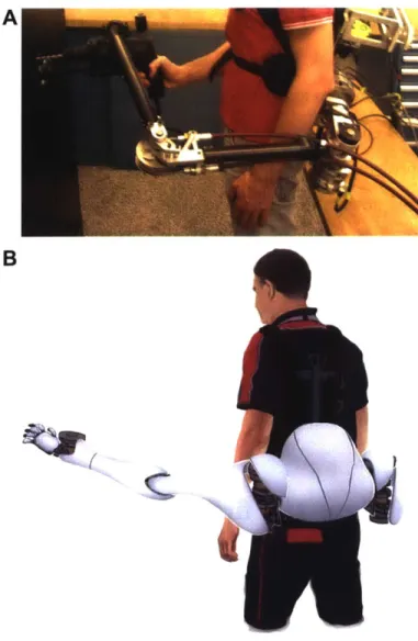
In this chapter, we will use a simplified version of the fourth prototype of the SRL, described in Chapter 8 (Figure 1). The motions of the extra limbs are controlled with muscle activation signals, measured by elecromyographic (EMG) sensors on the torso of the user [31, 20, 211. Each of the two additional degrees of freedom is con-trolled by two torso muscles located on the same side of the human body (Figure 2). In particular, contracting the right pectoralis major originates an upward rota-tion (flexion) of the right robotic limb, while contracting the right rectus abdominis
B
--
I
7 LI/ C DFigure 2-1: Subjects wearing the SRL and phases of the experiment to verify the
possibility voluntary, independent control of the system. (A) A subject wearing the
SRL. (B) The robot is worn at the hip of the user and the two extra limbs have one
powered degree of freedom each, allowing them to rotate in the sagittal plane about their base (a movement analogous to the flexion extellsion of the shoulder joint). (C) Phase 1 of the experiment, in which subjects do not wear the robot, and track the motions of two targets pointing at them with their natural arms. (D) In Phase 2 of' the experiment, subjects track two moving targets with the robotic limbs. (E) Phase 3 requires subjects to control four limbs at oiice - two natural arms and two robotic limbs - in order to track the motion of four targets..
determines a dowinward rotation (extension) of the same robotic limb. An analogous relationship connects the left-side lectoral and abdominal muscles to the notions of the left robotic limb. The muscle activation signals are acquired with a 2D0Hz sam-pling rate, low-pass filtered (Butterworth filter., 2nd order. 10Hz cutoff frequency) and transformed into reference velocity comrmands for the robot's motors, according to the control law:
ST
07-ef (0,C - 0)k + (Orc5 (01,bcc - A01,)k (2.1) 6)ki (1 WhOere 0rc is the reference velocity for the robotic limb, and 0 is its actual velocity.
(yrc and ol(j) represent the normalized muscle activation values for the pectoral and 24
E
0
A rghi ef1 B rightf
DD
181D
.
A
1
.
Figure 2-2: Control interface allowing the subjects to govern the motion of the robotic limbs, and sensors employed during the experiment. (A) Torso muscles used to control the extra limbs, and (B) the associated motions of the robot. Contracting the left pectoral miuscik raises the left robotic limb, while contracting the left abdominal iiuiscle lowers it. The same control scheme is replicated on the right side of the torso, for the right robotic arm. (C., D) Position of the sensors used on the front and on the back of the subjects. The yellow circles represent the locations of the EMG sensors used to measure the muscle activation signals of five couples of muscles. The area covered by each nuscle is outlined in a different color (yellow: pectoralis major, bhle: rectus abdoninis, green: deltoid. pink: trapezius and light blue: latissinus dorsi). The red circle represents the location of the reference (ground) electrode, while the green squares indicate the position of the accelerometers employed to ineasure the inclination of arms and torso.
abdominal muscles respectively (OnpJ,. 0(bs1). kc1 is a constant converting mscle
activation into a velocity reference, while k,, and ki are the gains of the velocity PI controller that regulates the niotion1 of the robotic 1ib. T is the torque conmand
sent to the imotor. This control scheme is applied to each robotic limb, separately. It allows to extend the synimetric, independent organization of the left and right natural limibs to the additional limbs. The control law also shows that the muscle activatimi
signals of the ipsilateral pectoral and abdominal muscles are subtracted. This is die
to the fact that the two imuscles control two different directions of, motion for the same robotic joint, acting like antagonistic muscles for the new degree of freedom.
Muscle activation is converted into a velocity reference for the robotic joint, so that a burst in the EMG signal (the typical muscle activation pattern starts from zero,
rises and then falls back to zero) generates a constant change in the position of the robotic limb. In other words, muscular activation is required to move the extra limbs
- generating non-zero reference velocities -but not to hold them at a constant position
- when the reference velocity is null.
We chose this control interface because it can enable the user to generate in-dependent commands for the robotic limbs. The human torso comprises numerous superficial skeletal muscles (at least 10 pairs), whose activation can be measured with non-invasive EMG sensors [6]. In particular, we selected the pectoral and abdominal muscles for the control of the robot. These muscles are simple and comfortable to access with state-of-the-art EMG sensors, can be voluntarily contracted without ef-fort, and are close to the physical location where the robot is worn. The reason why we focused on torso muscles is that they can activate in combinations that do not produce any motion of the body - for example, it is easy to contract the abdominal muscles without moving. These combinations of muscle activations belong to the null space of the torso. As long as the torso muscle activations lie in the null space, their
forces will balance each others and there will not be any resulting motion. This is
a higher-dimensional extension of the concept of co-contraction - the simultaneous
activation of two antagonistic muscles that does not result in a movement for the joint that they control (e.g. biceps and triceps co-contracting without originating elbow flexion or extension). In the context of this chapter, the key consequence of the existence of a rich, multi-dimensional null space for the torso is that its muscles are able to generate independent activation signals that do not influence the posture of the human body. This has the potential to enable a human subject to control extra
limbs without losing any natural degrees of freedom. Any other choice of control commands for the extra limbs (e.g. motion or muscle activation signals from the
nat-ural limbs, neck, face, tongue or eyes) would inevitably result in the loss of multiple natural degrees of freedom, re-directing them to the control of the robot [37, 4, 50].
2.3
Hypotheses
Based on these considerations, we formulate three main hypotheses. Hypothesis 1: it is possible to accurately control the extra robotic limbs, without influencing the posture of the human body. In particular, controlling the extra limbs does not require the loss of natural degrees of freedom - defined as preventing the motion of the natural limbs or forcing the subject to perform particular movements just to control the robot. As a consequence, we postulate that the coordinated control of natural and additional limbs allow subjects to perform a complex task better than just using the natural and artificial limbs separately, one after the other. Hypothesis 2: the direct, independent control of the robotic limbs is enabled by the use of torso muscle activation signals. The combinations of muscle activations used to generate control signals for the robot lie in the null space of the human torso. Moreover, these muscle activations are contained in a subspace that is different from the subspace of muscle combinations used to control the motion of the natural limbs. Hypothesis 3: there are natural limits to this approach, preventing it from being extended to an arbitrary number of extra limbs. More specifically, we expect the accuracy of the limbs (both natural and robotic) to decrease as we increase the number of limbs under the direct control of a human subject. However, we hypothesize that learning to control extra limbs is analogous to learning a new motor skill, and will therefore show performance improvement with consistent training.
2.4
Experiments
To test these hypotheses, we conducted experiments with healthy subjects (N=11).
All of the subjects were male, right handed, in good physical shape (20aEd'BMIaEd'30)
and between 23 and 37 years old. The participants to the experiment wore the extra robotic limbs, while standing in front of a set of four moving targets. The goal of the subjects was to track the motion of the targets by pointing at them with their natural arms and robotic limbs (Figure 1). Each limb was allowed only one degree of freedom
- the rotation about its base in the sagittal plane. In the case of the natural arms,
this motion corresponded to the flexion/extension of the shoulder joint. Subjects were asked not to move the other degrees of freedom of the shoulder, extending their arms and keeping their elbows and wrists rigid. The targets were placed at the end of carbon fiber rods, whose rotation was actuated by servomotors. The targets moved to a new position every 15 seconds, and held it until the next movement. The trajectories of the four targets were different, randomly generated and independent. The experiment consisted of three phases (Figure 1). In Phase 1, subjects did not wear the robot and simply tracked the motion of two targets with their two natural arms. In Phase 2, subjects wore the robot and tracked the motion of two targets with the two robotic limbs. They were instructed to relax their natural arms. In Phase 3, subjects wore the robot and tracked the motion of 4 targets using both their natural arms and the robotic limbs. Each subject participated to two experimental sessions for Phasel, three for Phase 2 and three for Phase 3. Sessions were divided into tracking trials which lasted for 3 minutes each. Phase 1 and Phase 3 sessions contained 3 trials, while Phase 2 sessions consisted of 5 trials. Subjects could rest between trials, and could not participate in more than a session per day. In all of the phases, we measured the rotation of the human arms (with accelerometers held in the hands) and the extra limbs (with the actuator sensors) in the considered degree of freedom (Figure 2). We also measured the rotation of the subject's torso in the sagittal and frontal planes (using an accelerometer taped on the upper chest). Finally, we used EMG sensors (Figure 2) to record the activation signals of the 4 muscles used to control the robot (pectoralis major and rectus abdominis, left and right) and of
6 additional torso and shoulder muscles (trapezius, latissimus dorsi and deltoid, left
and right).
All of the experiment subjects achieved accurate, voluntary control of the robotic
limbs (Figure 3). The movements of the extra limbs are strongly correlated with the trajectory of the targets (Figure 4), both in Phase 2 (r = 0.83) and in Phase 3 (r=0.77). This implies that the subjects were able to efficiently track the motion of the targets with the two additional robotic limbs, and maintained that ability when
Phase 1 Phase 2 Phase 3
_ L190 t, -Lget
) 0 10 10 0 0 40 80 1 '.'0 4 A I ti
4i 1 1 L) ;.j 146 ItIO 180 , AI4 j W. I 2 6k 40 ta0 180 time is]
0~~ L
2 40 0 0 1 0 10 0 4- 6 8 1 1 O 0 10
U 40 W) 80 1W01..0 140 180 1W0 . 40 a lIt 6 4. a,
time is] time Isl
Figure 2-3: Examples of the tracking perf'ormance of the subjects during the
exper-iment. The left coluuimn shows the best Phase 1 trial (tracking two targets with the
human arms). The central column shows the best Phase 2 trial (tracking two targets with the robotic liibs). 111(h right column shows the best Phase 3 trials (tracking four targets with the human arms aid the robotic linibs).
they were tracking two additional targets with their natural arms. As expected, the
correlation between the miotion of the huian arns aid their target trajectories is very high ii Phase 1 (r 0.93). Interestingly, this correlation remains high in Phase 3 (r- 0.77). This confirms that leariiing to control additional robotic Iimbs did not
affect the natural capacity of the subjects to control their own arnis. Moreover, our data show that controlling the motioii of the four limibs (both the robotic and the natural ones) did not affect the posture of the subjects, torso. Throughout the whole expleriient., the correlation between the target trajectories and the imotions of the torso was extreimiely low - never exceeding I --0.31 in the case of the natural arms,
and r -0.10 ii the case of the robotic limbs. Ini Phase 2, subjects actively controlled the motion of the robotic limbs, while relaxing their arns. There is imo correlation between the target trajectories for the extra limbs and the motion of the natural ars (r-- 0.00). This indicates that direct control of the robotic limbs does not influence
the posture of the natural arms. We also computed tbe target reaching tinme - the
time required for a limb to reach its target with a tracking error snaller than 10deg. Our results show that the average reaching tiie ii Phase 3 - when all four limbs were
llsed -is smaller than the sum of the average reaching times in Phase 1 and Phase 2
-when the two iiiiman arns and the two robotic imbs were used separately (Figure 5).
This iiieans that in Phase 3 sjects were able to execute the complicated tracking
task by coordinating the four liiibs. The direct, simlultaneous control of four limbs Yielded a better task performance (smaller reaching time) than simply executing a non-overlapping sequence of actions where the natural arns and the robotic inibs are activated one after the other.
A targets and arms, Phase I
240 20 0
EA
0 t0C D 40 J, o -e-r 0 43 5f) 0 50largets inrl torso. Phiis I
B targets and arms. Phase 2 0
40
4) --- 3 83
60
50 0 '0
E robot target Ideg]
targets and torso, Phase 2
C correlation between targets and arms, Phase 3
r 0.90 r 0 0.77 0 6 ~04[ 0 2 0 ~- --- --
---human arms robot arms
F correlation
between targets and torso. Phase 3
05' 0 -0,5 10
-60 40 20 0 20 40 W
human targets [deg]
if)
-60 -40 20 0 20 40 60
G robot targets [deg)
targets and human arm position, Phase 2
to
I
0
-60 -40 -20 0 20 40
robot targets fdegJ
Figure 2-4: Correlation betweeil the trajectories of the targets and the motion of
inbs and torso. (A) Correlation between the position of' the subjects, natural arms,
and the position of their targets. The grayscale bar on the right indicates the number of data points in each location of the plot. The red line is a linear fit of the data, and Pearson's correlation coefficient is r 0.93. (B) Correlation between the position of the robotic limbs, and the position of their targets. (C) Correlation coefficients between the motion of the limbs (divided in natural arms and robotic limbs), and their targets. (D, E. F) Correlation between the trajectory of the targets, and the motion of the subject's torso. (G) Correlation between the mnotion of' the robot targets, and the position of the human arn.
30
r = -0.21 r 010
Average reaching times, comparison across Phases Tsimultanaous E 3 L 2 1C 0
-Phase 1 (human) Phase 2 (robot) Phase 1 +Phase 2 Phase 3 (human and robot)
Figure 2-5: Average timie to reach thic targets iii all of the phases of the experimlent. Reaching time is compuited as the timec between the instant, when a target reaches its position, and the instant wheni the corresponding limb) reaches the target - withinl an interval of' As10dleg. For each trial, we calculated the average reaching timie of' every fimb. The bars in the figure displaY the mcani between the reaching timies of all limbhs and all trials for every phase of' the experiment. The third columin represents tile sumn of, the average reaching times of' Phase t and Phase 2. This is the average reaching timie that we would expect in Phase 3, if the subjects controlled the four limbhs
sequentially (one after the other). The red arrow indicates the difference between this
preictonand the actual average reaching timie of Phase 3. Since subjects are faster in reaching the four targets. they are employing the two natural armns and the two robotic limbIIs in a coordinated. simultaneous mtanner.
2.5
Discussion
Direct control of the robotic himbs wvas enabled by several factors, including the simple control interface, the presence of senisor~y feedback, and the uise of a velocity control strategy. The control interface for the robot (Figure 2) was based on torso mnus-cleslocted n te sae sde o th boy as the (ontrolled extra limb., and in the samne direction as the intended mnotion (pectorals to raise the limib. and abdomlinals to lower themn). We(, also employed the smallest numnber of' mutscles (four) necessary
to create an antagonistic control systemn for each of' the two artificial degrees of' free-domn. Subjects got casil'y accustomted to the relationship between the con t racti101
of their torso muscles and the corresponding robot motions. An accurate tracking performance was achieved by all of the participants within the time frame of the experiment (Figure 3, 4), which included six daily sessions with control of the extra limbs (Phase 2 and Phase 3). The subjects' average tracking performance increased from trial to trial, consistently with the features of the first, fast stage of motor skill learning [24, 41, 25, 46, 511. The presence of visual and haptic feedback was another key element of the experiment [44]. Sensory feedback has been proven to facilitate the learning of new motor skills, and even brain plasticity [71, 75]. Here, subjects tracked physical, rotating targets (Figure 1). They could also see the extra limbs moving in front of them as a consequence of the contractions of their torso muscles. And since the harness was securing the wearable system to the hip of the subjects, they were able to feel the reaction forces generated by the movements of the robotic limbs. Our data also confirm that employing muscle activations as velocity signals is an effective control strategy for tracking tasks where the goal is to accurately reach a position and then hold it. Subjects were able to track the targets both accurately and efficiently. The average muscular activation recorded in Phase 2 - when the natural arms were at rest - was 33% lower than in the other Phases. The reason is that this control scheme only requires muscle contractions to change the positions of the robotic limbs, but not to hold them in place. Conversely, when the natural arms were required to move the shoulder muscles had to be continually contracting in order to keep pointing at the targets in front of the subjects. This resulted in rapid fatigue symptoms for the deltoid muscles, and limited the number of tracking trials to three per session in Phase 1 and Phase 3 (the trials were 5 per session in Phase 2).
The motion of the robotic limbs did not influence the posture of the human body (Figure 4), because the subjects learned to use their muscles to generate indepen-dent control signals for the robot. The torso muscle activations associated with the movements of the extra limbs belonged to the null space of the torso. In fact, data from all of the three Phases of the experiment indicate that these combinations of muscle contractions did not influence the position of the torso. Moreover, subjects used different sets of muscles to control the robotic limbs and the natural arms
A B C
Phase 1 Phase 2 Phase 3
L."_Mu-ce RlghtMuO e Lett muscies Right M Uces Letules __RightMus cles
Fmm
_-r.P R TIap 3 R Te.0 71.rp RTa
-- e
.R ai -talR -a L LlRLA
1 05 0 3 05 10 3 3 55 1 3 35
n-m-k deninrzed dwagg norMalted -ghM normh2d d 9re -Mgnt -omne~ g" normah-d -gt
Figure 2-6: Main combinations of imuscles activated during the different phases of the
experiment. (A) The mliain muscle combinations used by subjects in Phase 1. These vectors have been extracted by applying non-negative matrix factorization (NMIF) to the muscle activation data recorded in Phase 1 - considering all of the subjects.
NIF outputs the feature vectors, displayed in the plot, that best approximate the
signals under analysis. lit this case. the right deltoid imiscle dominates the first feature vector, while the left deltoid imiscle dominated the second feature vector. This means that the natural armn movements - the only tracking iiovements present in Phase 1
- are dominated by the activation of the deltoid imuiscles. (B) T1'llhe main iiuscle
cominiatios ((d lby slbjects in Phase 2. The f our feature vectors are dominated by the abdominal and pectoral muscles, one for each combination. This is consistent
with the control sche( of the robotic limbs. which was based on those muscles. It also shows that there is nijinial overlapping with the other torso miiuiscles. and with the muiiscles ellplo'yed to control the motion oftthe natural arms. (C) The main mu11scle combinations used by subjects in Phase 3. The feature vectors present in the two previous phases continue to doiniiiate the muscular activation patterlls of subjects. Since the miuscle combinations used to control the natural arms and the robotic limbs do not overlap significantly, subjects collbille the previously learnied control strategies to achieve direct, coordinated control of four limbs.
ure 6). These sets of muscles have iminimal overlapping. and can therefore be used independently. In particular, the pectoral muscles are involved both in the natural notion of the human arms, and in the control of the extra linbs. However, the levels of activations required by these two tasks are different - a much stronger activation is needed in order to generate a control signal for the robot. This explains why the sane imiuscles could perform both functions without conflict, as a secondary coIpo-1ient of the muscle combinations employed to move the natural arms and as a priiary component of the imuscl( combinations employed to control the robotic limbs.
The main limit of this approach is that tracking accuracy decreases when adding
active degrees of freedoi 1111de. direct control of the subject (Figure 7). This rediction
A B Robot tracking performance with and without hunan tracking 0 U4 witlout humaiaMrns 1 meanw/iohummia 03 02 02 cosist6 0 t 1 12 14 1 6 04 e s dwth huma ao 2 , 02 04 0 6 068 1 1.2 14 1.6 tracking error RMS
Figure 2-7: Normalized tracking performance in the different phases of the
experi-ment. (A) Normalized root mean sqare (RMS) of the tracking error, as a function of the nugber of trials. Phase 1 consists of trials 1-6, Phase 2 consists of trials 7-21, and Phase 3 consists of trials 22-30. Solid lines represent the average RMS tracking error across all subjects, arid the shaded areas indicate the standard deviation. Thin lines and light shades refer to the human arms, while thick lines and dark shades refer to the robotic limbs. The dotted lines indicate the linear fit on the data. The learing rate - the reduction of the tracking error from one trial to the next - is fast in Phase
3, intermediate in Phase 2, and absent in Phase 1. This confirms that learning to
control extra limbs is analogous to learning a new motor skill. (B) Distribution of tracking errors for the robotic limbs in the Phase 2 trials. (C) Distribution of the tracking errors for the robotic limbs in the Phase 3 trials. The average tracking error increases as we add extra powered degrees of freedom to the human body.
in performance affects all of the limbs involved in the task. The average tracking error increases from Phase 1 to Phase 3 for the natural arms, and from Phase 2 to Phase 3 for the robotic limbs. At the same time, tracking accuracy gradually improves with training, confirming that subjects are adapting to the extra limbs as if they were learning a new motor skill. In particular, the learning rate (reduction of tracking error from trial to trial) is fastest in Phase 3, where both natural and robotic limbs are controlled by the subjects. While the learning rate is intermediate in Phase 2 (only robotic limbs), there is no significant learning in Phase 1 (only human arms). This is expected, because subjects have already refined the control performance of their natural arms over the years, arid do not niced t~o learn anything new to use them to track the target trajectories. Whenever we add the robotic limbs, though, subjects need to develop a new control strategy and the learning process is initiated.
2.6
Conclusions
We have demonstrated that humans can learn to accurately control additional pow-ered limbs, without influencing the posture of their natural body. The human neuro-muscular control system adapts to this new configuration in a few training sessions. The vast number of muscles in the human torso allows subjects to generate indepen-dent control signals. The combinations of muscles used to control the robotic limbs belongs to the null space of the torso, and does not significantly overlap with the set of muscles used to move the natural arms. The coordinated control of four limbs enables subjects to execute a tracking task faster than they would controlling single limbs or couple of limbs separately, one after the other. Tracking error increases with additional active joints, but consistent training leads to performance improvements analogous to learning a new motor skill. Adding powered degrees of freedom to the human body represents a new form of augmentation, capable of enabling the acqui-sition of new motor skills and the execution of new classes of complex, coordinated tasks.
Chapter 3
Design
3.1
Overview of the robot
Today's wearable robots closely mimic the structure of the human body. Wearable robots can be classified in exoskeletons, orthoses and prostheses
[32].
Exoskeletons are employed to augment the performance (strength, endurance, etc.) of their user, orthoses restore or assist impaired motor functions, and prostheses replace missing limbs. All of these systems are designed to follow the kinematic organization of the human body, and to provide assistance to the natural joints. They focus on supporting existing degrees of freedom, and do not increase the number of active degrees of freedom available to the user.We proposed a new kind of wearable robot that augments the user by provid-ing additional robotic limbs. These extra limbs are independent from the natural human body. Therefore, the number of active degrees of freedom available to the user is increased, opening up new possibilities in terms of executing complex tasks and optimizing assistance. Humans have already evolved to take advantage of the simultaneous use of multiple limbs. We hypothesize that increasing the number of limbs will enable users to perform new, coordinated tasks that would not be possible
- or would be significantly slower - using only the natural limbs. The increase in functionality brought about by extra limbs can be intuitively understood by trying to execute bimanual tasks (e.g. opening a bottle, carrying a large box) with only one
arm. We discussed this in detail in the previous chapter.
Another advantage of using independent robotic limbs is that their motions are not constrained to follow the motions of the user. This means that the robotic limbs are free to optimize their configuration to provide the best possible assistance, given the configuration of the user's body. Such optimal behavior is not available to traditional wearable robots, because their kinematic configuration must always follow the posture of the user joints to which they are attached. In Chapters 5, 6 and 7 we will take advantage of the independence of the robotic limbs to provide optimal weight support during static manufacturing tasks. In Chapter 8, the additional degrees of freedom of the robotic system will be employed to stabilize and assist quasi-static sitting/standing motions. In Chapter 9, the use of independent robotic limbs will enable a new balance augmentation strategy for dynamic walking.
The concept of the wearable robot is shown in Figure 1. The system is named Supernumerary Robotic Limbs (SRL) because of the new form of augmentation it provides. The robot is worn at the hip, through a harness composed of a belt and two leg straps. The base of the device follows the shape of the hip bone. The extra limbs extend outwards from the sides of the base. The range of motion of the robot is wide. For each robotic limbs, the workspace resembles a hemisphere centered on its base and extending outwards. The robotic limbs are able to reach up (like human arms), reach down (like human legs) and even reach areas that are outside of the workspace of the human limbs (e.g. behind the user). Each robotic limbs has three degrees of freedom (Figure 1). Two rotational degrees of freedom are located at the base of the limb, where it is attached to the base of the robot. The third degree of freedom is prismatic, and it is located axially in the limb itself.
In the following sections we will describe in detail the structure and the com-ponents of the latest SRL prototype (Figure 2). The harness and the base of the robot achieve a firm and comfortable fit with the human body, enabling the system to provide assistance without getting in the way of the user. The rotational degrees of freedom at the base of the robotic limbs have been realized with an innovative ball joint structure, able to bear the weight of the user without any heavy, conventional