Publisher’s version / Version de l'éditeur:
Vous avez des questions? Nous pouvons vous aider. Pour communiquer directement avec un auteur, consultez la première page de la revue dans laquelle son article a été publié afin de trouver ses coordonnées. Si vous n’arrivez pas à les repérer, communiquez avec nous à PublicationsArchive-ArchivesPublications@nrc-cnrc.gc.ca.
Questions? Contact the NRC Publications Archive team at
PublicationsArchive-ArchivesPublications@nrc-cnrc.gc.ca. If you wish to email the authors directly, please see the first page of the publication for their contact information.
https://publications-cnrc.canada.ca/fra/droits
L’accès à ce site Web et l’utilisation de son contenu sont assujettis aux conditions présentées dans le site LISEZ CES CONDITIONS ATTENTIVEMENT AVANT D’UTILISER CE SITE WEB.
Three-dimensional Image Capture and Applications III, Electronic Imaging 2000,
Proceedings of SPIE; Volume 3958, 2000
READ THESE TERMS AND CONDITIONS CAREFULLY BEFORE USING THIS WEBSITE. https://nrc-publications.canada.ca/eng/copyright
NRC Publications Archive Record / Notice des Archives des publications du CNRC :
https://nrc-publications.canada.ca/eng/view/object/?id=51520526-758a-427c-8321-ea8477ad4ac7
https://publications-cnrc.canada.ca/fra/voir/objet/?id=51520526-758a-427c-8321-ea8477ad4ac7
NRC Publications Archive
Archives des publications du CNRC
This publication could be one of several versions: author’s original, accepted manuscript or the publisher’s version. / La version de cette publication peut être l’une des suivantes : la version prépublication de l’auteur, la version acceptée du manuscrit ou la version de l’éditeur.
Access and use of this website and the material on it are subject to the Terms and Conditions set forth at
The ShapeGrabber Footscanner: a low cost high accuracy 3-D system
for the acquisition of human feet
Blais, François; Bisson, J. A.; Williams, S.; Robertson, N.; Rozin, S.; Nelson,
A.
National Research Council Canada Institute for Information Technology Conseil national de recherches Canada Institut de technologie de l'information
The ShapeGrabber Footscanner: A Low Cost
High Accuracy 3-D System for the Acquisition
of Human Feet *
Blais, F., Bisson, J.A., Williams, S., Robertson, N., Rozin, S., Nelson, A.
January 2000
* published in the SPIE Proceedings, Three-dimensional Image Capture and Applications III, Electronic Imaging 2000. San José, California, USA. January 23-28, 2000. Volume 3958. pp. 178-186. NRC 43617.
Copyright 2000 by
National Research Council of Canada
Permission is granted to quote short excerpts and to reproduce figures and tables from this report, provided that the source of such material is fully acknowledged.
header for SPIE use
SPIE Volume ?, Three-Dimensional Image Capture and Applications III, Electronic Imaging 2000, San Jose, California USA, 23-28 jan. 2000, pp. 178-186.
The ShapeGrabber FootScanner: a Low Cost High Accuracy 3-D System
for the Acquisition of Human Feet
*F. Blais
a**, J.A. Bisson
b, S. Williams
b**, N. Robertson
b, S. Rozin
b, A. Nelson
ba
National Research Council Canada / IIT, Ottawa, Ontario, Canada, K1A-0R6
bVitana Corporation, Ottawa, Ontario, Canada, K1H-1E1
ABSTRACT
This paper presents a new acquisition method and the application of the technology for the acquisition of a person’s foot. The sensor is designed to meet the requirements of measuring a variety of feet under various ambient optical conditions that can, in other circumstances, seriously affect the data measurements and reduce the reliability of the system. The most important distinction between this ranging method and other more classical approaches is the high tolerance of the method to external optical perturbations as well as reflections from other sensor heads. This allows its use in conventional “store” or “medical offices” that are usually bright places.
Keywords: Three-dimensional, foot scanner, range, laser sensor, virtual aperture, registration, calibration
1. INTRODUCTION
The main purpose of the ShapeGrabber FootScanner system, presented in this paper, is to acquire the 3-D shape of a person’s foot in a reliable manner. The sensor is designed to reduce the cost of the unit as well as to meet the requirements of measuring a variety of feet under various external uncontrolled conditions of operation. The basic system is shown in Figure 1 and includes three optical sensor heads and a linear motion stage used to translate the three sensor heads over the whole length of the foot. The sensors cover the bottom and the two sides of the foot. Although this system was primarily designed for scanning feet, it can also be used for other objects.
In order to be able to operate under various uncontrolled conditions and produce an accurate 3-D representation of computer models of the foot, the following requirements are imperative:
1. Accurate and fast acquisition of 3-D shape information
2. High dynamic range sensor (color) and sufficient volume (range) 3. Elimination of optical perturbations introduced by
• External ambient light sources such as open windows and fluorescent lights • External reflections on the optical surfaces
• Reflections and cross-talk from other sensor heads • Multiple reflections from within sensor head
4. Elimination of system optical distortions (lens, glass surfaces) 5. Rigid transformation of the data into a single global coordinate system 6. Data stitching and creation of an accurate computer model of the object 7. Real-time display and data manipulation
*
NRC 43617 **
SPIE Volume ?, Three-Dimensional Image Capture and Applications III, Electronic Imaging 2000, San Jose, California USA, 23-28 jan. 2000, pp. ?-?.
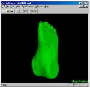
Figure 1: ShapeGrabber FootScanner System. Figure 2: 3-D model created from multiple view registered range images.
The most important distinction between this ranging method and other more classical approaches is its high tolerance to external perturbations. This allows the use of the system in conventional retail stores or medical offices that are usually very bright places. For example, the sensor system could be located close to an open window or fluorescent. Because any one of the sensors can directly look at these bright sources of light, the optical detector can saturate, or worse produce distorted measurements. Furthermore, the operation and manipulation of the scanner by non-specialists in public places and low cost requirements also add to the complexity of the problem:
1. Eye safety: requires the use of low laser power and indirectly increases the susceptibility of the system to ambient light
2. Low cost: introduces high variability in the system optical components, configuration, and the use of non-coated glass surfaces (more optical reflections)
3. Maintenance and operability issues (ease of use)
Figure 3: Effects of ambient lights and the camera heads’ field of view of the acquisition system. On the left, the bottom sensor will be affected by ceiling lights; on the right, the side sensor heads will see open windows.
Bottom Sensor
Field of View Lateral
Sensor Field of View
SPIE Volume ?, Three-Dimensional Image Capture and Applications III, Electronic Imaging 2000, San Jose, California USA, 23-28 jan. 2000, pp. ?-?. The acquisition process is schematized in Figure 4 and requires harmonious fine-tuning of each of the basic elements of the acquisition chain, mechanics, electronics, and software.
Figure 4: The acquisition chain.
2. TRIANGULATION AND RANGING
Two popular techniques used for optical ranging of a target surface [1] are known respectively as the standard optical triangulation system and the Biris (bi-iris) system (Figure 5), the latter employing a dual aperture mask within a lens system of an imaging device having a position sensitive detector, e.g. a CCD camera. Both methods are based on triangulation equations to calculate range information.
Figure 5: Two commonly used ranging methods; (a) standard triangulation, (b) Biris method.
Essentially, in order to determine the distance to a point within an image, a triangle is formed with the point at a vertex. A detector, commonly a CCD imaging device, forms another corner of the triangle. By knowing some of the dimensions of the triangle, a distance from the detector to the point within the image can be determined. This is referred to as triangulation. For example, stereoscopy, which mimics the human vision system, requires two detectors to be able to image a scene. Each image is analyzed to extract the same feature. The two detectors and the feature form the three vertices of a triangle and triangulation is performed. Known problems with such methods include computational complexity, feature extraction problems, and perspective related problems that can reduce accuracy. For acquiring human shape, the lack of distinctive features on the skin is particularly problematic and therefore requires the use of external light sources.
Laser Lens CCD Object P1 Laser Lens Biris Mask CCD Object P1 P2
a)
b)
Scanning Head Video Processor Intrinsic SensorCalibration Scanning System<Translation> Camera
Model
Raw Data Range Data
Linear Stage Model
Calibrated Range Data
Multiple view integration <Rigid Transformation(s)> Multiple View Model(s)
SPIE Volume ?, Three-Dimensional Image Capture and Applications III, Electronic Imaging 2000, San Jose, California USA, 23-28 jan. 2000, pp. ?-?. The most common approach to active triangulation uses only a single detector and a laser (Figure 5a). The laser shines a target in the form of a dot of known color onto a surface and the detector images the dot. The detector, laser, and dot form the angles of a triangle. Though such a system is useful in controlled environments, when one tries to use it in uncontrolled environments, noise and other issues prevent accurate measurement of distances. The Biris system [2,3] uses a laser to form a target as well as a dual iris detector for forming an image with two separately imaged views of the target (Figure 5b). This permits verification of target position and increased accuracy. An advantage of the Biris system is its small size and the robustness of the range sensor. In [4], the accuracy of the basic focusing method was greatly improved by combining this basic approach with the standard triangulation method without compromising its tolerance properties to ambient optical perturbations. The Biris system is better than the conventional triangulation systems, because it uses the redundancy introduced by an aperture mask to validate the measurements and to compensate for small errors introduced into range measurements due to detector resolution.
Unfortunately, new generations of CCD and CMOS image detectors are smaller due to newer technologies, again to reduce production costs. For example, at present most newly released CCDs measure 1/3" compared to 2/3" of the former generation. To obtain the same field of view with a 1/3" CCD image detector as with a 2/3" CCD image detector a lens of half the focal length is needed. Because the lens size is reduced, the overall aperture sizes are also reduced. This results in two apertures having very small dimension allowing less light to pass through to the detector. Furthermore, the contribution of the very small aperture separation to the triangulation becomes negligible. This makes the method more prone to false measurements (see section 3).
In [5] range measurement using a beam splitter is discussed. Two different images of a single feature are superimposed on a screen, for example. The superposition is performed using a beam splitter or semi-transparent mirror. This allows viewing of the feature from two different "locations" a greater distance apart. The two images of the feature are then adjusted so that the feature overlaps itself. Once the feature is coincident, a triangle is known between the mirrors and the feature. This system provides a greater base for triangulation increasing accuracy of the range measurement. Unfortunately, commonly a human operator is used to overlap the image. Even when automated, since feature extraction is a difficult process, the accuracy of such a system reduces to the accuracy of a known stereoscopic triangulation system with the same drawbacks.
The proposed method provides a range sensor that is highly accurate and reliable. This is accomplished by using a beam splitter to provide a plurality of images of a target point on a surface, each image relating to a triangle having a different triangle base for use in triangulation of target point than the other images. This reduces the number of false measurements and increase overall accuracy.
3. RANGING PRINCIPLE
The quality of a range measurement is related to its reliability, accuracy, and precision. When an optical range sensor is used, the precision of any measurement is related to the resolution of the optical sensor. Taking a plurality of measurements of a point increases the reliability and accuracy of the range measurement derived from the plurality of measurements. This is because a plurality of measurements increases reliability and allows error averaging within each measurement.
In Figure 5b, a laser diode projects a target point onto the target surface. The Biris imaging device is comprised of a double aperture mask to create a doubled image of the target point on an imaging detector. The output signal of the CCD across a scan line produces two peaks p1 and p2. Once the locations of the two peaks are determined, a range distance is calculated using triangulation. 1 1 1 1 1 p l D f f l l z ⋅ ⋅ − + = − (1)
SPIE Volume ?, Three-Dimensional Image Capture and Applications III, Electronic Imaging 2000, San Jose, California USA, 23-28 jan. 2000, pp. ?-?. 2 2 1 2 1 p l D f f l l z ⋅ ⋅ − + = − (2)
where zi is the range from the sensor lens to the target surface, for a given triangulation base Di (the distance between the laser projection and the lens aperture), l is the focusing distance, and f is the focal length of the lens. Because of the fixed and known opto-mechanical geometry of the ranging head, it will be demonstrated that, if more than two peaks are detected, only one pair of peaks pi will give the same ranging value z (section 4).
From the previous equations, range accuracy is given by
i i i p D f z z ∆ ⋅ = ∆ 2 (3)
where ∆p is the error on the peak position measurement. To increase the accuracy of the range sensor either the focal length f
or the triangulation base D has to be increased. Unfortunately the value of f is also related to the field of view and to the physical CCD size. Cost considerations result in a choice of a small CCD. Since field of view is defined as follows:
⋅ ⋅ = f CCD 2 tan 2 ϕ (4)
where CCD is the length of the CCD detector. For example, with a field of view of about 30° and a 2/3” detector (CCD=8.8 mm), then a focal length of 16 mm is required. Because it is preferable to maintain a reasonably wide field of view, as CCD size is decreased for production cost reasons, f must also be decreased. Reducing f results in increased values for ∆z.
Therefore, with reduced CCD size, it is important to increase the triangulation base D (equation 3). To increase sub-pixel detection ∆p the lens or mask aperture must also increase. However the lens being so small it becomes impractical to use the
principle of Figure 5b; maximum aperture separation is limited by the numerical aperture of the lens f-number f/#:
/#
f f
d < (5)
The optical principle of the proposed 3-D range sensor head is shown in Figure 6. A laser projector projects, for example, a single line or multiple parallel lines onto a surface. A CMOS detector is oriented to receive light from the target point via at least two different optical paths. The first optical path is drawn in Figure 6 as a straight line from the target point to the detector passing through a beam splitter and a lens. The second optical path is shown as a line from the target point to the reflective surface (mirror or prism). Light incident on the reflective surface is reflected to the beam splitter and from there through the lens to the CMOS detector. Thus, the detector captures two coincident images of the target point, one along each of the two optical paths. Advantageously, a conventional low cost and small camera/lens system is sufficient to ensure the accuracy of the range measurements; the difficulties associated with mask apertures are alleviated.
Figure 6: Optical principle of the proposed ranging method
Laser
P1 P2
Mirror or prism
Beam
splitter
Lens
CCD
Object
SPIE Volume ?, Three-Dimensional Image Capture and Applications III, Electronic Imaging 2000, San Jose, California USA, 23-28 jan. 2000, pp. ?-?.
Figure 7: Unfolded optical paths creating a virtual multiple view system (BiView)
The two optical paths result in the detection of two images of the target point, each captured from a different viewing angle. This results in a range sensor equivalent to a stereoscopic vision system (Figure 7). Due to asymmetry and scaling effects of the method, the two corresponding peaks are not necessarily within the same scan line. In order to use such a system, the determination of corresponding target points and false measurements is important. Once two corresponding points that represent valid range data are determined, a range is calculated having increased reliability due to the significant triangulation base D (equation 3).
Such a range method is advantageous in providing accurate and reliable range information due to the use of two distinct triangulation bases. Also, cost advantages result from the use of a single small size CMOS detector. The use of a beam splitter allows the system to obtain two images of a target point from two different viewing angles. The number of false measurements due to other light sources or multiple reflections on the target surface that cannot be filtered is substantially reduced.
The method also provides increased lens aperture compared to the two small mask apertures system. Therefore, substantially more light is provided to the detector and signal sensitivity is thereby increased. Of course, the cost and size advantages of using a single small CMOS detector, in order to determine accurate range, is evident and allows for the implementation of a low cost range sensing system that is robust and useful in many environments.
4. RANGE VALIDATION
Validation is used to isolate the valid peaks used to calculate range. This allows the filtering of peaks resulting from ambient illumination, other light sources, and multiple reflections. Given a set of peak positions pi,v where v is the video line and i is an index to the peaks within that line, the validation method consists of finding, for each video line v , a set of peak pairs in the form pi,v; pj,w that minimizes the equation
( )
2 , min ξij ∀i,j (6) wherein[ ]
jw v i j i, = p, −Fv p, ξ (7)[
p v]
w=G i,v, (8)with Fv and G being validation functions based on the ranging equations 1 and 2 but including the calibration of the lens distortions [4]. The validation process of equation 6 is equivalent to obtaining a single range measurement z, given by equations 1 and 2.
p1
SPIE Volume ?, Three-Dimensional Image Capture and Applications III, Electronic Imaging 2000, San Jose, California USA, 23-28 jan. 2000, pp. ?-?. The method of validation is dependent on certain known characteristics of a range sensor obtained during calibration. First, with a single image of a single point, a range is determinable and, therefore, it is evident that for each peak position there is a single unique range measurement. Since two images are superimposed, for each peak there exists two possible range measurements depending on which optical path the peak is associated with. A distance to the target point can be calculated using triangulation. For that distance, there is a single unique point formed on the detector, resulting in a unique peak position, along the second optical path. Similarly, a unique peak position results for each of any number of optical paths. By verifying that a peak exists at the corresponding unique peak position, the selected peak position is validated as a "real" first peak position within a set. When the corresponding peak is not present, the selected peak position is not a "real" first peak position. For a single target point and two optical paths, a set of two peak positions that correspond to a same range measurement are eventually found and a single range measurement is determined from both peak locations.
Because of the fixed arrangement of the optical components only one pair of peaks is likely to satisfy this condition when a single target point is projected onto the surface.
5. PRACTICAL IMPLEMENTATION, CALIBRATION, AND POSE ESTIMATION
Figure 8 shows the practical implementation of the ranging principle. Dimensions of the mechanical triangulation head are 4 cm × 4 cm × 8 cm. A small 1/3” inch CMOS detector is used for signal detection. Figure 9 schematizes the complete optical head implemented for this purpose. Flat mirrors are used to reduce the overall dimensions of the sensor head, folding the different optical paths within the range sensor head.
Figure 8: The optical triangulation sub-assembly, and its associated electronics.
Figure 9: System triangulation head. Mirrors are used to reduce the overall dimensions of the scanning head.
Figure 1 shows the assembled ShapeGrabber FootScanner System (protective cover removed). It consists of three of the range sensor heads described previously, mounted on a linear translation motion stage that scan the object under measurement. Each range sensor head projects a laser line profile on the surface of an object, the laser lines being mechanically moved to scan the surface of the object. Two of the sensor heads (Figure 3) will measure the two sides and the top of the foot shown in Figure 1, a third sensor head scans the bottom section of the foot.
For each video frame, the projected laser line is imaged by a video camera (CMOS Imager) and processed to extract the location of the laser lines on the imager. Using the previously demonstrated triangulation method the X-Y-Z coordinates of the projected points on the surface of the object are calculated and an accurate 3-D representation of the shape of the object is obtained. Field of View Depth of View Laser Plane Laser
SPIE Volume ?, Three-Dimensional Image Capture and Applications III, Electronic Imaging 2000, San Jose, California USA, 23-28 jan. 2000, pp. ?-?. In practice, an optical system is far from perfect; spurious reflections must be removed and system distortions and mechanical tolerances must be compensated for. The following operations are implemented in real-time by the system:
i) Video detection
(1) Detection of the position of laser line/points in the video signal (2) Removal of the false measurements, ambient light, and reflections ii) Intrinsic calibration
(1) Compensation for the lens aberrations and other system distortions (2) Computation of the triangulation equations
(3) Compensation for the diffraction effect of a glass/window interface used to protect the optical equipment iii) Extrinsic calibration (motion calibration)
(1) Coordinate transformation from the laser plane/scanner coordinate system to the linear mechanical stage coordinate system
(2) Linear translation of the sensor heads iv) Extrinsic calibration (pose estimation)
(1) Coordinate transformation of each sensor head measurement into a single, global X-Y-Z coordinate system. v) Application specific data processing to eliminate remaining outliers and/or systematic interference from
mechanics, and optical reflections on the glass surfaces (e.g. using bounding box)
The video signal is processed in real-time using a dedicated Field Programmable Gate Array (FPGA). The detected laser peak positions and intensities are sent to a Pentium processor running Windows 98, across the Universal Serial Bus Interface (USB). Plug & Play capabilities make the system completely transparent to the user.
The importance of proper calibration can be illustrated by the fact that range data that results from merging two range images with improper calibration, either from uncompensated system distortions or from bad extrinsic calibration, will obviously create erroneous or biased object surfaces. With proper calibration, redundancy in the multiple views and surface continuity can be used to remove any remaining undesired optical reflections and spurious measurements.
The combined intrinsic calibration and motion estimation procedure results in a set of separate X-Y-Z coordinate systems, one for each sensor head. Given two sets of independent but orthogonal X1-Y1-Z1 and X2-Y2-Z2, pose estimation consists of evaluating the rigid transformation matrix M that will transform one set of measurements, from one sensor head, into the other set’s coordinate system. Usually the bottom scanner is used as a reference. The procedure essentially consists of simultaneously measuring, from each sensor head, common points visible from both sensors; then the rigid transformation M is easily computed.
6. EXPERIMENTAL RESULTS
Figure 2 shows the result of combining the three sets of range data together acquired with this system, under adverse ambient light conditions often encountered in public places. The system was tested in a room with direct sunlight and bright ceiling lights. As previously mentioned, open windows will have a direct impact on one or both side range sensors, being directly within the field of view of the camera. Lights on the ceiling will affect principally the bottom range sensor that is looking up at the bottom of the foot (Figure 3).
With proper calibration, we found that absolute accuracy was close to the theoretical resolution of each sensor head taken separately. Accuracy for a single camera head was measured to be 0.15 mm RMS. Standard deviation errors, that include motion and pose estimation, were measured at 0.3 mm for the volume of measurement of 10 cm × 10 cm × 30 cm. Acquisition time is less than 10 seconds for the whole system. Table 1 resumes the characteristics of the complete scanning system.
SPIE Volume ?, Three-Dimensional Image Capture and Applications III, Electronic Imaging 2000, San Jose, California USA, 23-28 jan. 2000, pp. ?-?. Sensor head dimensions 18 cm ×15 cm ×12 cm
Measurement volume 10 cm × 10 cm × 30 cm
Image dimensions 356 × 340
Range accuracy (sensor) 0.15 mm
Volume accuracy X-Y-Z 0.3 mm
Acquisition time 11 sec (30 Hz)
Table 1: System specifications
7. CONCLUSION
The proposed ranging method is an important departure from the dual aperture mask system. Being very similar to the Biris method in terms of the type of the detector image produced, it still benefits from all the advantages of the processing algorithms, accuracy and reliability of the measurement, and solves the problem of small imager dimensions. This new method uses a beam-splitter to create a “virtual” multiple apertures optical system providing high tolerance to false measurements and good range accuracy.
The Foot Scanner system based on this technology has been used to acquire 3-D data from a person’s foot in a reliable manner. A motion stage was used to simultaneously translate three sensor heads in order to acquire a complete scan of the foot. Probably the most important distinction between this ranging method and other more classical approaches is the high tolerance of this method to external optical perturbation. This allows the use of the system in conventional retail stores or medical offices that are usually unfriendly and uncontrolled bright places for high accuracy optical ranging systems.
8. REFERENCES
1. F. Blais et al., "Practical Considerations for a Design of a High Precision 3-D Laser Scanner System", Optomechanical
and Electro -optical Design of Industrial Systems, SPIE Vol. 959, 1988, pp 225-246.
2. M. Rioux et al., "Compact Three-Dimensional Camera For Robotic Applications", Journal of the Optical Society of America, Vol. 3, p 1518, September 1986.
3. F. Blais et al., "Optical Range Image Acquisition for the Navigation of a Mobile Robot", Proceedings of the 1991 IEEE
International Conference on Robotics and Automation, Sacramento, California, April 1991.
4. Blais, F. et al., “Calibration of an anamorphic laser based 3-D range sensor”, SPIE Proceedings, Videometrics V, San Diego, CA. July 27 -1 August 1997. Volume 3174. pp.113-122.
5. Warren J. Smith, "Modern Optical Engineering", Second Edition, McGraw-Hill, 1990, pp. 254-257. 6. E.Hecht, A.Zajac, “Optics”, Addison-Wesley, 1979.