HAL Id: hal-02045580
https://hal.archives-ouvertes.fr/hal-02045580
Submitted on 22 Feb 2019HAL is a multi-disciplinary open access
archive for the deposit and dissemination of sci-entific research documents, whether they are pub-lished or not. The documents may come from teaching and research institutions in France or abroad, or from public or private research centers.
L’archive ouverte pluridisciplinaire HAL, est destinée au dépôt et à la diffusion de documents scientifiques de niveau recherche, publiés ou non, émanant des établissements d’enseignement et de recherche français ou étrangers, des laboratoires publics ou privés.
An industrializable Silicon-based microhotplate for
metal oxides gas sensors
P. Yoboué, A. Konaté, O. Asseu, Philippe Menini
To cite this version:
P. Yoboué, A. Konaté, O. Asseu, Philippe Menini. An industrializable Silicon-based microhotplate for metal oxides gas sensors. Physical and Chemical News, Best Edition, 2014, 72, pp.34 - 41. �hal-02045580�
Physical and Chemical News, ISSN 1114-3800,
Volume 72, April 2014, pp 34-41
An industrializable Silicon-based microhotplate for metal oxides gas sensors
1P. Yoboué*, 1A. Konaté, 1O. Asseu*, 2,3 P. Ménini
1Ecole Supérieure Africaine des Technologies de l’Information et de la Communication (ESATIC), Abidjan, Treichville,
Km4 Bd de Marseille, Cote d’Ivoire(http://www.esatic.ci/)
2CNRS;LAAS; 7, avenue du colonel Roche, F-31077 Toulouse, France 3Univ de Toulouse; Université Paul Sabatier Toulouse3, F-31062 Toulouse, France
* Corresponding author. E-mail: [email protected] ; [email protected]
Abstract
This article presents an industrializable silicon-based microhotplate for metal oxide gas sensors. It introduces an interesting approach and describes the technological optimizations used to reach high and stable operating temperature, in reducing intrinsic drift problems (due to commercial polysilicon heater). The microhotplate present low consumption of 70 mW for 600°C, good thermal homogeneity over the active area and a good mechanical stability.
Keywords: Microhotplates, Platinum, Metal oxides, Micro technology, Industrializable, Commercial gas
sensors.
Nomenclature SnO2: Tin dioxide.
WO3: Tungsten trioxide.
ZnO: Zinc oxide.
SiO2/SiNX: Silicondioxide/ siliconnitride.
PECVD: Plasma-Enhanced Chemical Vapor
Deposition.
TiN: Titanium Nitride
F.E.M: Finite ElementMethod.
Rho: Theoretical heater resistance at 20°C, .
Uh: voltage supply for microhotplate, V. T: Temperature, °C.
1. Introduction
Metal oxide gas sensors constitute one of the most widely used and investigated types of gas sensors (journals [1]; [2]). Today, they are more and more attractive in a lot of fields of application, especially for automotive or environment fields to detect hazardous gases with a network of autonomous and distributed micro-sensors. The reason for this great interest is their low cost, ease
of use and the large number of gas that they can detect.
Metal oxide gas sensor’s structure detailed in (journals [3]); it had generally two parts:
Sensitive layer which is a metal oxide semiconductor such SnO2, WO3, ZnO…
Microhotplate which is used to activate thermally the metal oxide layer.The microhotplate has a heater and is used to set the operating temperature
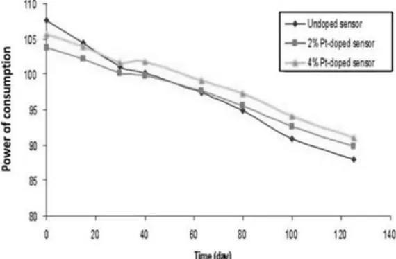
Having a stable operating temperature is very important for the reliability of gas sensors. Bad stability can decrease characteristics of sensor such its sensitivity, selectivity or lifetime. The worst case is the destruction of the sensor. Industrialized and marketed micro gas sensorsfound use polysilicon micro-hotplate but this technology drifts significantly with temperature, that induces drift of sensor sensitivity and cannot definitively be used over 450°C
without degradation (Figure 1). This figure shows a drift of micro-hotplate’s power for 3 different gas sensors supplied at 500°C. An irreversible decrease of the power is shown even if polysilicon
is doped with platinum.Other examples of tests carried out confirmed those results (journals [4]; [5]).
Figure 1: Time drift for 3 gas sensors.
The drift can be explained by a diffusion of doping elements (phosphorus) through grain boundaries in poly-silicon due to high level of current density.
In short, polysilicon microhotplate’s drift causes bad stability of the heating and so a bad stability of sensitivity or bad reproducibility. These problems are also due to the uncontrolled morphology of the sensing layer and its thermal drift.So, a microhotplate without any polysilicon material is adopted. The new heater consists of a platinum resistor. The use of this material would have theoretical advantage to reach high level of temperature (around 650°C compare to 450°C with polycrystalline silicon) (journals [6]). This device can allow controlling more precisely the temperature on the active area.
Firstly, this article firstly deals with the approach to realize a heating platform dedicated to metal oxide gas sensors with high and stable operating temperature. Then, technological process implemented will be described and characterizations conducted will be presented.
2. Approachto realize an efficient microhotplate
2.1 First works
First works led concerned a microhotplate, where the classical polysilicon microhotplate had been replaced by a platinum one. It was used to heat sensitive layer at high temperature (from 300°C to 500°C), in order to allow the detection (oxidation or reduction) of various gases. Temperature is an important parameter; it has an influence on the sensitivity and the selectivity of the sensor. So, the more temperature is controlled, the more reliable sensor is.
As presented in figure 2, the devise was structured as this: a silicon-substrate with a 2 μm-bilayer SiO2/SiNX membrane on which it was
successively deposited Ti/Pt-resistor, a PECVD-SiO2 insulated layer, interdigitated Ti/Pt
electrodes. Finally, the last but not least step of the process is the backside releasing of the membrane by DRIE (Deep Reactive Ion Etching).
For Ti/Pt-resistor, two different shapes of heaters (meander and spiral) have been investigated in order to optimize the yield (temperature vs. power of consumption) in taking the classical meander form as reference.
Three variants for every shape have been studied. Figure 3 summarizes studied structures. In this article, the work has been focused on variation
of the width of metallization and the spacing pitch (Figure 3).
Meander structures are numbered from A to C. For this shape, fixed and modulated spacing pitches have been studies.
Spiral structures are numbered from D to F. Variable spacing pitch is adopted for spiral shape. Studies showed good temperature homogeneity with variable spacing pitch (journals [3]).
Figure 3: Different heater resistor shapes studied: (a-e) 20 m of metallization width, (f) 30 m of metallization width, (a-b) fixed spacing pitch and (c-f) variable spacing pitch
Figure 4 presents an example of FEM simulations results concerning shape A and shape D in term of temperature profile according to x
axis. The length explored corresponds to the active area (300 μm: center ±150 μm).
Figure 4: Example of Electro-thermal modeling results (FEM simulations) for (a) meander shape A and (b) spiral shape D
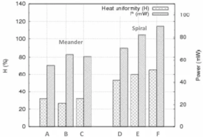
Temperature profile of the spiral presents a hot spot at the center of the membrane. Temperature gradient over the active area is lower than the one of the heater with meander shape: 0.3°C/m for spiral shape and 0.5°C/m for meander shape. Moreover results about these heater resistor geometries, it clearly appears from figure 5 that spiral heater presents good homogeneity on active area.
In this article, temperature homogeneity H (%) has been defined by:
a T
S
S
H
(%)
40 , SΔT<40 corresponds to the surface area where thetemperature gradient is lower than 40°C (ΔT<40°C)
Sa: Active surface area (surface occupied by the
sensitive layer).
Figure 5: Example of Electro-thermal modeling results for different heater resistor shapes: Power of consumption and Homogeneity rate for Tmax =650°C.
Considering these results, the double spiral form with variable pitch D is chosen. Indeed this form presents the better compromise between the thermal homogeneity through sensitive layer and power consumption. Results are confirmed in literature (journals [3]). Infrared measurements show that this platform can reach 600°C with low thermal inertia (≈10ms only) that allows very fast operating temperature changing. This microhotplate is able to reach ∼475°C for a temperature of 80 mW. However, a drift of the microhotplate for temperatures more than 500°C is
observed. This drift is supposed to be a degradation of titanium adhesion layer (journals [7]; [8]).
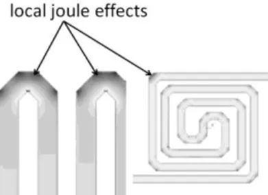
More precise FEM simulations have been realized to analyse local joule effect in the heater. Figure 6 shows clearly that the current density is more important in angles than in the rest of metal. That leads a joule effect more important in angles and can degrade locally the heater. It also could be a cause of long term heater resistance drift or irreversible degradation.
Figure 6: Example of Electro-thermal modeling results for two different heater resistor shapes: local joule effects in angles
In view of those results, optimizations of this microhotplate have been opted. The work is to improve and optimize the previous Pt-Heater developed in order to obtain a more stable and controlled temperature beyond 500°C.
2.2 Optimizations
The modifications brought to previous Pt-microhotplate were integrated to the previous process. The optimized microhotplate has been elaborated integrating design and technology modifications in order to improve significantly its performances in term of mechanical deformation, temperature homogeneity, power consumption,
and long term stability at high operating temperature.
The optimizations concerned two main points:
New design of heater
The previous heater with a 400 μm*400 μm double spiral and almost square form (Figure 8-a) has been replaced by a new double spiral and circular one (Figure 8-b). The diameter of the new heater is 300 μm. Moreover, current equipment (VARIAN 3/19) enables us to optimize deposits of 150 nm/15 nm of Pt/Ti (titanium used as adhesion layer for platinum on silicon substrate) followed by a specific annealing temperature.
Figure 8: Different designs of micro-hotplate: (a) previous design, (b) new design
New design of membrane
Instead of the 2 μm-square SiO2/SiNX
membrane, a rounded and thinner one is adopted. It got a thickness of 1.4 μm (SiO2/SiNX of 0.8
μm/0.6 μm). This new thickness of SiO2/SiNX
should have the advantage of reducing mechanical constraints (journals [9]; [10]; [11]). Final result is presented in figure 9-b. Membrane’s diameter (dm)
was 1200 μm. The diameter allowed having a
geometry factor dm/dh of 4. This factor defined as
the ratio of membrane diameter on heating area diameter (dh) reflects the thermal losses due to the
membrane. According literature, it is necessary to keep this factor greater than 3 in order to have low heat losses (journals [12]). For the optimized device, this condition was respected.
Figure 9: (a) Previous structure; (b) New micro hotplate developed
All those modifications should allow us to reduce degradations on the layer and to optimize temperature on the sensitive layer area. The goal was also to obtain the most homogeneous and high temperature on the sensitive layer area, in order to reduce the consumed electric output and then to improve mechanical reliability.
3. Results
Simulations have been led to compare the two structures. With this microhotplate structure, the absence of angles minimized local joule effects. Indeed in figure 10-b, current density was important and homogeneous along shorts streamlines (center of heater).
Figure 10: Joule effects increasing from blue to red in a) Previous structure and b) New structure
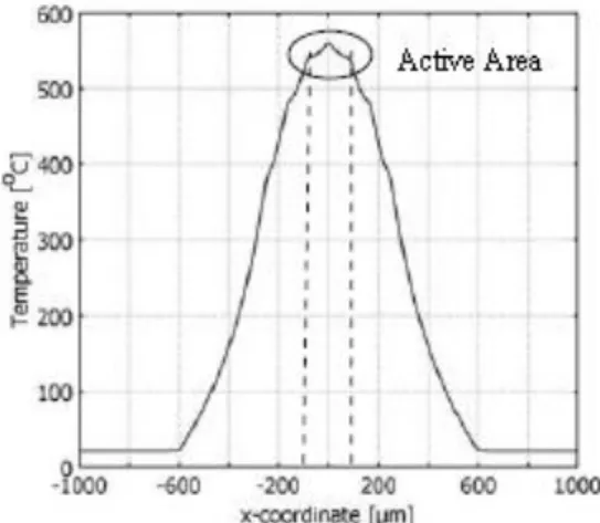
Thermal distribution simulations carried out been led on 150 m diameter active area centered with heater.An average gradient of 0.25°C/μm is obtained with maximal temperature of 550°C (Figure 11). This result is higher than what can be found in the literature(journals [3]). A gradient of 0.05°C/μm was found. This couldberelated to thelow temperature (in comparison with ours)at
which thegradientwas determined(460°C). Moreover TiN has been used instead of Ti as an adhesive layer of the platinum on silicon substrate. Even if the gradient obtained with the optimized device is high, it appeared enough good for our applications at higher temperatures.Those results given at 550°C were confirmed experimentally.
Figure 11: Electro-thermal modeling results for the new structure: temperature profile through x axis
In figure 12, optimized Pt-microhotplate easily reached 600°C with only 70 mW. That is interesting in comparison with the result of previous microhotplate (400°C at the same power). And then, it could be seen in that experimental thermal measurements with infrared
camera are in good accordance with numerical simulation results. The new structure allowed decreasing the power of around 30% for a given target temperature.
Fig. 12: Comparison between experience and electro-thermal modeling results for the new heater resistor; comparison also with the previous microhotplate performances
Concerning mechanical reliability, the shape of the membrane contributed to minimize these deformations: the circular membrane presented uniform concentric deformations (figure13) contrary to square membrane which has a cross shape deformation due to the angles (figure 9-a). The rounded thinner membrane of 1.4 μm allowed decreasing the thermal inertia and to minimize intrinsic mechanical constraints. Indeed, the maximal deflection of the previous Pt-structure could reach 8μm at rest. At higher operating
temperatures, nonlinear variations of several micrometers were observed.
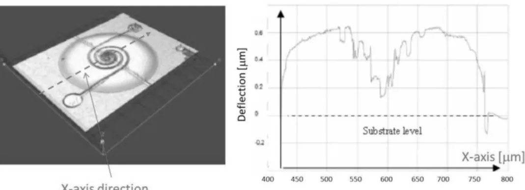
The new structure contributed to reduce the deflection around 0.5μm only with low variations in functioning (some hundreds of nm) as it is shown in figure 14. In addition, it should be noted that these results were obtained with complete structure including all metalized layers (very stressed) and validated in the total operating temperature range.
Fig. 13: Measurements of membrane deformations from optical profiler: 3D image and deflection out of functioning along X-axis direction
Figure 14: Measurements of membrane deformations from optical profiler: maximal deflection for different heater voltages (i.e. for different temperatures)
These optimizations concerning the membrane appeared very important for gas sensors used with pulsed temperature in term of reliability of the hotplate but also of the sensitive layer (adherence and morphology).
Finally, a six-month test has been conducted on several microhotplates. Each platform has been powered by a chosen and constant Uh voltage (6
V, 7 V and 8 V). Results show very good stability of this structure contrary to polysilicon heater that always drifts at 450°C.It can be seen on figure. 15 that the heater resistance remained stable for supply voltages lower than 7 V that corresponds to around 60 mW (500°C). For higher supply voltage (8 V), it can be observed an irreversible ageing (during 20 days) before stabilization.
Fig. 15: Ageing of heaters at 3 different voltage supplies (Uh = 6 V, 7 V and 8 V) 4. Synthesis
Table 1 synthesizes the characteristics of the two generations of platforms. Optimized microhotplate is clearly more efficient.
Previous microhotplate New microhotplate Membrane deflection 8 m ± 5 m 0.5 m ± 0.2 m
Heater drift at 500oC 10%
Stable ( 0.3%)
Table 1: Comparison of the two Pt-microhotplates developed
5. Conclusion
This article presents technological optimizations of a micro hotplate based on Ti/Pt heater. The objective was to improve performances in term of mechanical deformation, temperature homogeneity, power consumption, and long term stability at high operating temperature.
Results obtained showed that the characteristics are stable until 550°C. That corresponds to a great improvement compared to the structure using the poly-silicon. Above this temperature, this kind of metallization is well known to be unusable because of titanium diffusion and oxidation. The second generation enables to reduce the power consumption of 30% and the maximal deflection by a factor 10. All these improvements are suitable for reliable gas sensors.
References
[1] N. Barsan, D. Koziej, U. Weimar,Sensors and Actuators B 121 (2007) 18–35
[2] C. Wang, L. Yin, L. Zhang, D. Xiang, R. Gao, Sensors 10 (2010), no. 3, 2088-2106.
[3] M. Baroncini, P. Placidi, G. C. Cardinali, A. Scorzoni, Sensors and Actuators A. 115 (2004) 8-14.
[4] D. Briand, P.Q. Pham, N.F. de Rooij, Sensors Actuators A 135 (2006) 329-336.
[5] C. Shi, X. Liu; R. Chuai,Sensors 9 (2009), no. 2, 1141-1166
[6] J. Spannhake, O. Schulz, A. Helwig, A. Krenkow, G. Muller, T. Doll,Sensors (2006) 405-419.
[7] K. Sadek, W. Moussa, Sensors (2007) 319-340.
[8] U. Schmid, H. Seidel, Thin Solid Films516 (2008): 898-906.
[9] C. Escriba,E. Campo, D.Esteve, J.Y. Fourniols, Sensors Actuators A 120 (2005) 267-276.
[10] K. N. Andersen,W.E. Svendsen,T. Stimpel-Lindner,T. Sulima, H. Baumgartner, Appl. Surf. Sci. 243 (2005), 401-408.
[11] R. Yuxing, D. Lam, Materials Science and Engineering: A467 (2007) 93-96.
[12] I. Simon, N. Barsan, M. Bauer, U. Weimar, Sensors and Actuators B. 73 (2001) 1-26.