Publisher’s version / Version de l'éditeur:
Vous avez des questions? Nous pouvons vous aider. Pour communiquer directement avec un auteur, consultez la première page de la revue dans laquelle son article a été publié afin de trouver ses coordonnées. Si vous n’arrivez pas à les repérer, communiquez avec nous à [email protected].
Questions? Contact the NRC Publications Archive team at
[email protected]. If you wish to email the authors directly, please see the first page of the publication for their contact information.
https://publications-cnrc.canada.ca/fra/droits
L’accès à ce site Web et l’utilisation de son contenu sont assujettis aux conditions présentées dans le site LISEZ CES CONDITIONS ATTENTIVEMENT AVANT D’UTILISER CE SITE WEB.
Proceedings of the International Society for Photogrammetry and Remote
Sensing (ISPRS) XXth Congress, 2004
READ THESE TERMS AND CONDITIONS CAREFULLY BEFORE USING THIS WEBSITE. https://nrc-publications.canada.ca/eng/copyright
NRC Publications Archive Record / Notice des Archives des publications du CNRC :
https://nrc-publications.canada.ca/eng/view/object/?id=936df4fb-3b4c-4da2-af14-a68177fea59d
https://publications-cnrc.canada.ca/fra/voir/objet/?id=936df4fb-3b4c-4da2-af14-a68177fea59d
NRC Publications Archive
Archives des publications du CNRC
This publication could be one of several versions: author’s original, accepted manuscript or the publisher’s version. / La version de cette publication peut être l’une des suivantes : la version prépublication de l’auteur, la version acceptée du manuscrit ou la version de l’éditeur.
Access and use of this website and the material on it are subject to the Terms and Conditions set forth at
Photo-Realistic 3D Reconstruction of Castles with Multiple-Sources
Image-Based Techniques
National Research Council Canada Institute for Information Technology Conseil national de recherches Canada Institut de technologie de l'information
Photo-Realistic 3D Reconstruction of Castles
with Multiple-Sources Image-Based
Techniques *
Gonzo, L., El-Hakim, S.F., Girardi, S., Picard, M., Whiting, E.
July 2004
* published in the Proceedings of ISPRS XXth Congress. Istanbul, Turkey.
July 12-23 2004. pp. 120-125. NRC 48047.
Copyright 2004 by
National Research Council of Canada
Permission is granted to quote short excerpts and to reproduce figures and tables from this report, provided that the source of such material is fully acknowledged.
PHOTO-REALISTIC 3-D RECONSTRUCTION OF CASTLES WITH
MULTIPLE- SOURCES IMAGE-BASED TECHNIQUES
Lorenzo Gonzo a, Sabry El-Hakim b,*, Michel Picard b, Stefano Girardi a, Emily Whiting c a Center for Scientific and Technological Research, ITC-irst, Trento, Italy - (lgonzo; girardi)@itc.it
b Visual Information Technology (VIT), National Research Council, Ottawa, Canada -
(Sabry.El-Hakim; Michel.Picard)@nrc-cnrc.gc.ca
c Department of Architecture, Massachusetts Institute of Technology (MIT), Cambridge, MA, USA
Commission V, Working Group V/2
KEY WORDS: Architecture, Cultural Heritage, Integration, Modeling, Virtual Reality, Photogrammetry, CAD. ABSTRACT:
Digitally reconstructing a large and complex heritage site, particularly medieval castles, for documentation, research, and virtual reality simulation is a challenging task. Castles by design contain many lines of defense such as inner and outer rings of walls and are often located on high grounds, surrounded by water or forests. They also have protective entrances, towers, courtyards, and a mixture of large complex buildings. Although laser scanners have many advantages, they may be impractical for reconstructing an entire castle. They are not portable or fast enough and can generate a huge amount of data that is difficult to register and visualize in real time. Therefore, we set out to fully explore the potential of only image-based techniques for modeling castles. We captured aerial and ground-based images and used existing floor plans and limited surveying, which compelled us to develop a technique to assemble and integrate models made from different data sets. We will discuss the issues and problems associated with modeling castles, give details of our approach, and present and evaluate the results of modeling the Stenico castle in Trentino, Italy, as a test-bed.
*Corresponding author
1. INTRODUCTION
Castles are unique structures that were assembled over different periods and follow no conventional architectural design. They were built for defensive purposes and had to make the most of readily available natural protective settings like hilltops and end of ridges. They were fortified with multiple rings of high walls, gates, and towers. As a result, data acquisition and modeling of castles are complicated. Two types of model are desired, one for a photo-realistic walkthrough animation or a movie that shows every attribute, and one for interactive visualization where trade-off between true-to-life details and speed (limited by computer hardware) must be made. The latter model is the most challenging and also it is the most demanded by end users.
Figure 1: Aerial views of Stenico castle over Stenico village. We initiated a castles documentation and visualization project, beginning with the Stenico castle (figure 1). The castle is one of the oldest and most important medieval castles in Trentino, and is an interesting mixture of styles of buildings added over several centuries. A view of the castle is depicted in the January panel of the “cycle of months” frescoes in Aquila Tower at Buonconsiglio castle in Trento, which we modeled in another project [El-Hakim et al, 2003b.] The goal of the new project is to reconstruct all castle buildings, courtyards, protective walls, and interiors particularly frescoed rooms. The cost and data collection time must fit the limited budget and granted access
time, noting that comparable projects took years to finish. The planning phase of the project revealed several problems in 3-D reconstruction of castles, as can be perceived from figure 1: 1. Due to castles location, it is hard to find an adequate number
of places from which to capture images or scans.
2. The assumptions made on standard architecture to obtain 3D data and increase automation are not applicable. We clearly cannot assume parallelism, perpendicularity, or symmetry. 3. The complexity and variety of architecture make it difficult
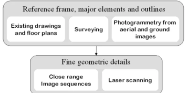
to capture all details without extensive manual interaction. Previous work suggested that combination of laser scanning and Photogrammetry both aerial and terrestrial, surveying, and other data such as maps or floor plans, are all needed to fully model large complex sites [EL-Hakim, 2001]. Figure 2 summarizes available techniques and their anticipated use.
Figure 2: The available techniques and their potential use. Since image-based techniques entail the most economical and portable sensors and the shortest on-site data collection time, we decided to carry out the first phase of the castle-modeling project with these techniques. We expect to add laser scanning in the next phase. In the first phase we specifically required to:
1. Identify the main problems in creating accurate and photo-realistic castle models using solely image-based techniques. 2. Evaluate using low-altitude aerial images for 3D modeling.
We need to determine the achievable accuracy at the rather long range from which the images are taken, the quality of point extraction, and the effect of integrating the resulting model with ground-based models. Accurately surveyed points should be used to evaluate the accuracy.
3. Develop a technique to combine image-based models with each other, and with models from other sources such as floor plans. The technique must remove overlaps and fill gabs between models to create a model suitable for visualization. In the remainder of the paper we give an overview of methods being used for modeling castles in section 2. This will lead to analysis of the problems in section 3, then the details of our approach in section 4. Results of modeling the Stenico castle are given and evaluated in section 5, followed by conclusions.
2. PREVIOUS WORK
Digital recording of complex sites like castles belongs to a large body of work in 3-D modeling. Organized by the technique, related work, albeit not at all comprehensive, is reviewed next. 2.1 CAD with Architectural Drawings / Floor Plans
Traditional 3-D CAD techniques using architectural drawings remain the most common [Forte et al, 1998, Haval, 2000]. Many use synthetic textures, which yield a computer-generated look. Textures from images offer more realistic appearance [DeLeon, 1999, Foni et al, 2002]. The approaches typically lack automation, although Dikaiakou et al, 2003, modeled heritage buildings in Nicosia using an automatic building generation technique based on a library of predefined 3D building blocks. 2.2 Surveying and Interactive Photogrammetry
Hanke et al, 2002, modeled the medieval fortress Kufstein, Austria, using images taken from a helicopter a by metric film camera, ground images by non-metric camera, and surveying. CAD software was used to fill in missing parts. Bacigalupo and Cessari, 2003, used Photogrammetry and surveying to model medieval castles in Western Sicily. The methods are still labor intensive and the projects may take several years to complete.
2.3 Automated Image-Based Modeling
To our knowledge, no large complex-site model was completed based purely on fully automated image-based techniques, but sections of castles were modeled automatically [Pollefeys et al, 1999]. Closely spaced images, like low-resolution videos, are required for robust matching. This may be difficult to acquire for a complete castle. Even if accessibility is not an issue, covering a large site with closely spaced image sequences is time consuming. Also, accuracy becomes an issue on long image sequences due to error propagation. However, the technique can be useful on parts of the site, like stonewalls with well-defined features. Most of the efforts are focused on the automatic recovery of internal and external camera parameters and the stereo matching of extracted points. On the other hand, acquiring points suitable for modeling and creating the model itself, which involves segmenting the point clouds into topologically meaningful groups, remain interactive [Gibson et al, 2003]. Many techniques attempting full automation of the modeling process [Werner and Zisserman, 2002, Wilczkowiak
et al, 2003], or improving the final models accuracy [Cantzler, 2003], were developed. The techniques rely on constraints of surface shapes and assumed relationships between surfaces, or require vanishing points from sets of parallel lines.
2.4 Laser Scanning
Several large-scale projects acquired all the geometry by laser scanning [Cain et al, 2002, Allen et al, 2003, Fruth and Zakhor, 2003]. Laser scanners promise to provide highly detailed and accurate representation of any shape [Blais, 2004]. Combined with color information, either from the scanner itself or from a digital camera, a realistic-looking model can be created. The accuracy at a given range varies significantly from one scanner to another. Also, due to object size, shape, and occlusions, it is usually necessary to use multiple scans from different locations to cover every surface. Aligning and integrating the different scans will affect the final accuracy of the 3-D model.
2.5 Combination of Multiple Techniques
Borg et al, 2002, modeled parts of a temple in Malta using Photogrammetry for outlines and laser scans for details, plus surveying to register the data. Georgopoulos and Modatsos, 2002, utilized available tourist slides, and existing engineering drawings and geodetic measurements to model the church of Holy Sepulchre in Jerusalem. Bundle adjustment with self-calibration on the digitized slides, with geodetic and engineering drawings measurements as control, was used in that 7-years-long project. El-Hakim et al, 2003a, used aerial and terrestrial images for the main shapes, and laser scanning for fine geometric details to fully model the abbey of Pomposa in Italy. Flack et al, 2001, developed tools specifically designed to assemble models created by various techniques.
3. CASTLE MODELING: ISSUES AND ANALYSIS The following sub-sections discuss the problems, in different categories, of existing methods applied to castle modeling. 3.1 Data Acquisition
As mentioned above, castles setting and the multiple lines of defense make it difficult to find suitable locations to take images or scans. Also the size and complexity of the structures will require a huge amount of data to cover all the details. Low-flying helicopter may be the solution to cover outer walls, roofs, and courtyards with a practical number of images. Ground images or scans at selected locations can furnish the details of some of the areas not visible from the helicopter.
3.2 Modeling from Floor Plans
After acquiring all possible sensor data, we may still have some sections without coverage. These parts can be determined from existing architectural drawings or floor plans. In the case of drawings created directly in digital form from surveying data, file formats such as AutoCAD or DXF allow the information to be arranged in separate layers, each containing a different element. Some adjustments to obtain consistent local geometry and layout topology are needed. Creating 3-D models may be done interactively on simple floor plans, but can be time consuming and error prone on complex buildings. Thus, some semi-automatic techniques were developed to create 3-D models from floor plans [Lewis and Sequin, 1998]. Commercial CAD software does not address the situation where a floor plan
drawing already exists. Therefore, significant research has been devoted to convert such drawings to CAD representation. This can be difficult due to the complexity and variety of drawing notations and the necessity to handle noise and unwanted features. Kernighan and Van Wyk, 1996, developed a technique that can extract lines and poly-lines from digitized floor plans and remove any information not needed for 3-D modeling.
5- Create detailed models from terrestrial images and, when available, a high-accuracy laser scanner.
6- Register and integrate the models created from sensor data. 7- Parts without data exposure are completed from floor plans.
Missing sensor data can be intentional for uninteresting parts, or inevitable due to lack of access or improper coverage. We detail some of the steps in the following sub-sections. 3.3 Limited Geometric Constraints
4.1 Camera Calibration Many of the automated modeling techniques mentioned in 2.3
rely on assumptions made about surface shapes and relations between surfaces such as plane perpendicularity and parallelism and the availability of vanishing points from multiple sets of parallel lines. However, in medieval castles these assumptions do not apply to most of the structures (see figure 1). This limits the applicability of many automated techniques. Therefore, we have to acquire the 3-D coordinates based only on overlapped images without assumptions. The exceptions may be arches, columns, doors and windows whose shapes are mostly regular and can be modeled semi-automatically [El-Hakim, 2002].
Self-calibration is necessary if camera settings are unknown and vary between images. But to achieve accurate self-calibration, certain geometric configurations of images are needed. Since this is not guaranteed at the project site, and makes imaging more restrictive, it is sensible to decide on high-quality camera and take the images at fixed known settings. Many modern digital cameras can save a number of settings. We then calibrate in the lab at those settings using surveyed points (figure 4).
3.4 Model Assembly and Integration
Models created from different sets of data and floor plans must be assembled to create one model suitable for visualization. In addition to differences in coordinate systems and scale, the models will also not perfectly match at joint primitives such as surfaces, edges, and vertices. Some of those will overlap or intersect and some will be disjointed, which is unacceptable for visualization. Again, commercial CAD and rendering software do not address these problems. Therefore, a procedure must be developed to seamlessly put together different models into one.
Figure 4: Calibration targets placed on walls, floor and ceiling. 4.2 The Overall Model from Aerial Images
4. DETAILS OF THE APPROACH
Traditionally aerial images are used to model terrain and roof tops. Here we suggest images from a low-flying helicopter at various viewing angles around the castle to model roofs, outside of buildings, most of the courtyards, surrounding walls, and close-by grounds. The images should have strong geometric configurations - being convergent with large base-to-height ratio. Bundle adjustment is applied, using some surveyed points to define the reference coordinate system and the scale. Our approach is inspired by the Level Of Detail (LOD) concept,
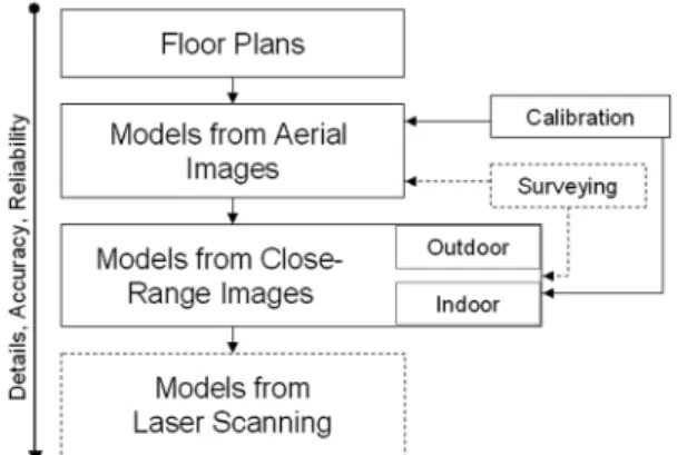
used in visualization of complex models. Some city modeling techniques also use an adaptation of this idea [Lee and Nevatia, 2003]. Our procedure is hierarchical by the data source (figure 3). In the hierarchy, the details, accuracy and reliability increase as we advance from one data level to the next. As a rule, data in one level overrides the data in previous levels.
4.3 Three-Dimensional Information from Floor Plans 3-D information from floor plans has two main purposes: 1. To add 3-D sections missed by imaging or scanning.
2. To support the modeling process by verifying surface shapes and the relationships between surfaces. Those are often not obvious from images or even from visiting the site.
To convert the floor plans into a 3-D model we need to provide semantic information such as room identities and connecting openings followed by walls extrusion to given heights. The heights will be known from the image-based models. Window and door insertions are carried out where needed.
Figure 3: Hierarchy of model assembly (dotted means optional).
The approach can be summarized as follows, noting that the
first five steps can be done in any order or even simultaneously: 4.4 Detailed Models from Ground Images
Images from ground levels are used to semi-automatically create detailed models of selected elements such as entrances, sections occluded from the aerial views, and indoor spaces. We start by manually creating a less-detailed model with selected seed points using bundle adjustment. Then, we select two 1- Acquire a floor plan in digital form and create rough model.
2- Calibrate the digital camera for its internal parameters. 3- Survey some points with total station.
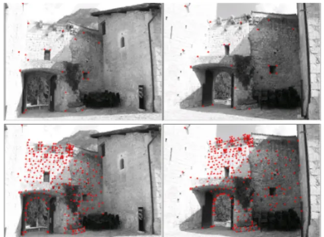
images with the best geometric configuration, and apply our hierarchical matching procedure developed in El-Hakim, 1989 (similar idea is proposed by Ferrari, et al 2003). Corners are automatically extracted followed by stereo matching procedure, constrained by the epipolar line and disparity-range determined automatically from the seed points. Finally, 3-D points on regular shapes like columns, arches, doors, and windows are created semi-automatically using also selected seed points, as described in El-Hakim, 2002.
Figure 5: Top pair with manually picked seed points, bottom pair with automatically matched points on a castle entrance.
Figure 6: Two adjacent models connected by a portal. 4.5 Model Assembly
Combining models created by different data sets, such as the two models shown in figure 6, must address several issues so that the final model is appropriate for 3-D visualization: • Relative scale and orientation must be correctly determined. • Joint primitives, specifically surfaces, edges, and vertices,
from adjacent models must match perfectly. However, it is unlikely that we have the same primitives between the adjacent models. For example an arch may have 50 vertices in a detailed model but only 8 in a general model.
• Sensor-based techniques produce actual wall surfaces rather than perfect planes. In contrast, wall surfaces from floor plans are extruded using user provided heights, thus they are exactly planes. This can be visually noticeable for adjacent surfaces between the two types of model.
• No gaps, redundant or intersecting edges are acceptable. Commercial modeling tools do not deal with these issues, thus special techniques and software tools were needed. The models can be registered manually in modeling software such as 3ds
max® using common points between them. The process will be
unnecessary if the individual models were directly created in the same coordinate system using control points. Many models however will not have any access to control points and will need interactive registration. Once all models are registered, the
integration procedure begins. The models are organized in a hierarchical manner where the top model contains the least details (Figure 3). We import points from the detailed model along the perimeter of common surfaces into the less-detailed model. Then we adjust the latter’s mesh with the new added points to create a hole into which we insert the detailed model without overlaps. Any remaining gap between models is filled from the floor plans. Then points from adjacent models on the borders of the gap are used to re-triangulate it so that we have realistic surfaces rather than perfect planes in the filled gap.
5. MODELING OF THE STENICO CASTLE The above procedure is applied to modeling the Stenico castle, which consists of the following components (figure 7):
• Buildings of mixed styles organized around 4 courtyards. The buildings include the 12th-century House of Nicholas and Walled House, the 13th century Court of Justice and Council
Hall, and the 15th century House of Johan Hinderbach.
• Inner and outer tall thick walls with arched gates. • A Renaissance loggia built by Clesio.
• The clock tower and the Fune or Bozone’s tower.
• Ramps and staircases to the multi-level building entrances. • The 13th century San Martino’s chapel with medieval frescos.
• Rooms with Renaissance frescos.
Figure 7: Sample project images of some castle elements. 5.1 Data Acquisition
We used a 5-mega-pixels Olympus® E-20 digital camera. Figure
8 shows camera positions from the helicopter over the castle.
Figure 8: Actual locations of the used aerial images. The same camera was used to take several sets of ground images for outside detailed and room models. The imaging, both aerial and terrestrial, took a total of 4 hours in two visits to the site. Two camera settings were used during the project, one
at the shortest and one at the longest focal length depending on the available space around the object. Besides the cost of the digital camera, other data acquisition costs include the rent of the helicopter for one hour and surveying of 115 points (one day) with a Leica® total station.
5.3 Assessment of the Models Accuracy
The castle structures extended over an area of about 100 meters by 64 meters and have up to 35 meters height. The castle is elevated by over 30 meters above the road approaching it. The aerial images were taken from an average range of 120 meters and average vertical distance of 65 meters above the castle. The field of view of each image usually covered at least all the buildings, with an average view width of about 160 meters. One pixel in the image corresponds to about 8 cm. The accuracy is assessed by the variance-covariance matrix of the adjusted 3-D points, and validated by surveyed checkpoints that had 3 mm accuracy. The achieved accuracy was in fact homogeneous and averaged: 17mm (X), 15mm (Y), and 16mm (Z). This is one part in 10,000 and represents 0.2 pixels. For the ground-level models, we achieved accuracies of: 1mm to 2mm, which give average relative accuracy of one part in 6,000 and represents 0.3 pixels. The superior relative accuracy reached from aerial images, even though they were taken from much longer ranges, is attributed to the better geometric configuration compared to ground images. Ground images had less than ideal locations due to obstructions and tight spaces around most buildings. 5.2 Modeling Results
ShapeCapture® [http://www.shapecapture.com] software has
been used for calibration, bundle adjustment, and image-based modeling. A general model was created from the aerial images, and several detailed models were created using sets of ground images, including models of the St. Martin’s chapel, the towers, the loggia, the entrances, and details of the walls enclosing the courtyards. Figures 9-11 show snapshots of some models.
5.4 Model Assembly
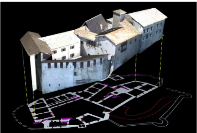
Applying the procedure presented in section 4.5, we started by superimposing the general model on the floor plan (figure 12). Sections missing from the general model were added from the floor plan using known wall heights. Detailed models such as the gate in figure 10, and indoor models such as the chapel in figure 11, were then inserted. In figure 13, the gate, windows, and wall top edge connect the general model and the detailed model. Points along those common regions were first used to register the two models. Then only points along the top of the wall and bottom of the gate were kept in the general model, and new points were imported from the detailed model. The general model was then re-triangulated to account for the point changes and to create a hole where the detailed model was inserted. Figure 9: General model of castle buildings.
Figure 10: Model of a castle entrance.
Figure 12: The main model superimposed on the floor plan.
Figure 11: Part of the model of St. Martin’s chapel.
6. CONCLUDING REMARKS
Although the castle-modeling project is still a work in progress, we have reached solid conclusions about the effectiveness of image-based techniques for this purpose. Using images taken from a low-flying helicopter and from ground levels, combined with existing floor plans and limited surveying, we can completely model a complex castle such as the Stenico castle with realistic details. Semi-automated modeling and model assembly techniques were developed. On average, less than 20% of all 3-D points were created interactively while at least 80% were created automatically. The cost and time required was much less than reported similar work. In the future, we will use an accurate laser scanner on some parts of the castle to add higher levels of detail to the model. This will require further advances to cope with the increase in model size.
Acknowledgements
We express our thanks to Dr. Franco Marzatico, the director of Castelli Trentini, and the Autonomous Province of Trento for allowing us access to the Stenico castle.
References
Allen, P.K., et al, 2003. New methods for digital modeling of historic sites. IEEE Computer Graphics and Applications, 23(6), Nov./Dec., pp. 32-41.
Bacigalupo, C., Cessari, L., 2003. Survey techniques and virtual reality for recovery plan of a fortified Mediterranean town, Int. Workshop Vision Techniques for Digital Architectural and Archaeological Archives, Ancona, July, pp. 40-42.
Blais, F., 2004. Review of 20 years of range sensor development, J. Electronic Imaging, 13(1), Jan., pp. 232-240. Borg, C.E., Cannataci, J.A., 2002. Thealasermetry: a hybrid approach to documentation of sites and artefacts. CIPA-ISPRS Workshop on Scanning for Cultural Heritage Recording, Sept., Corfu, Greece, pp. 93-104.
Cain, K., Martinez, P., Munn, J., 2002. Digital documentation for the Zawiya and Sabil of Sultan Farag Ibn Barquq, Cairo, http://www.insightdigital.org/papers.htm (accessed April 2004). Cantzler, H., 2003, Improving architectural 3D reconstruction by constrained modeling. Ph.D. Thesis, School of Informatics, University of Edinburgh, Scotland.
DeLeon, V., 1999. VRND: Notre-Dame cathedral, a globally accessible multi-user real-time virtual reconstruction. Proc. Int. Conf. Virtual Systems and Multimedia (VSMM’99), Dundee, Scotland, Sept., pp. 484-491.
Dikaiakou, M., Efthymiou, A., Chrysanthou, Y., 2003. Modeling the walled city of Nicosia, 4th International Symposium on Virtual Reality, Archaeology and Intelligent Cultural Heritage (VAST’2003), pp. 57-66.
El-Hakim, S.F., 1989. A hierarchical approach to stereo vision,
Photogrammetric Engineering & Remote Sensing, 55(4), April,
pp. 443-448.
El-Hakim, S.F., 2001. 3-D modeling of complex environments, Proc. SPIE Vol. 4309,
Videometrics and Optical Methods
for 3D Shape Measurements, Jan., pp. 162-173.
El-Hakim, S.F., 2002. Semi-automatic 3d reconstruction of occluded and unmarked surfaces from widely separated views, Proc. ISPRS Symp., Corfu, Greece, Sept, pp. 143-148.
El-Hakim, S.F., Beraldin, J.-A., Picard, M., Vettore, A., 2003a. Effective 3D modeling of heritage sites, 4th Int. Conf. 3D
Imaging and Modeling (3DIM'03), Banff, Canada, pp. 302-309. El-Hakim, S.F., et al, 2003b. Visualization of highly textured surfaces, Proc. VAST 2003, Brighton, UK, Nov., pp. 231-240. Ferrari, V., Tuytelaars, T., Van Gool, L., 2003. Wide-baseline multiple-view correspondences, Proc IEEE CVPR, pp. 718-725. Flack, P., et al, 2001. Scene assembly for large scale urban reconstructions, Proc. VAST 2001, pp. 227-234.
Foni, A.E., Papagiannakis, G., Magnenat-Thalmann, N. 2002. Virtual Hagia Sophia: restitution, virtualization and virtual life simulation. UNESCO World Heritage Congress, Oct.
Forte, M., Borra, D., Pescarin, S., Ronconi, C., 1998. The Estense Castle of Ferrara: multimedia project and virtual reconstruction, 3rd Int. Conf. Cultural Heritage Networks
Hypermedia, Milan 12-15 Sept.
Fruth, C., Zakhor, A., 2003. Constructing 3D city models by merging aerial and ground views. IEEE Computer Graphics
and Applications, 23(6), Nov./Dec., pp. 52-61.
Georgopoulos, A., Modatsos, M., 2002. Non-metric bird’s eye view, Proc. ISPRS Comm. V Symp., Corfu, pp. 359-362. Gibson, S., Hubbold, R.J., Cook, J., Howard, T.L.J., 2003. Interactive reconstruction of virtual environments from video sequences. Computers & Graphics, 27, pp. 293-301.
Hanke, K., Oberschneider, M., 2002. The medieval fortress Kufstein, Austria – an example for the restitution and visualization of cultural heritage, Proc. ISPRS Comm. V Symp., Corfu, Greece, Sept., pp. 530-533.
Haval, N., 2000. Three-dimensional documentation of complex heritage structures, IEEE Multimedia, 7 (2), Apr-Jun, pp. 52-56. Kernighan, B.W., Van Wyk, C.J., 1996. Extracting geometric information from architectural drawings. Proc. Workshop on Applied Computational Geometry (WACG), May, pp. 82-87. Lee, S.C., Nevatia, R., 2003. Interactive 3D building modeling using a hierarchical representation, IEEE Workshop Higher-Level Knowledge in 3D Modeling and Motion Analysis (HLK’03), with ICCV’03, Nice, October, pp. 58-65.
Lewis, R., Sequin, C., 1998. Generation of 3D building models from 2D architectural plans, Computer-Aided Design, 30(10), Sept., pp. 765-779.
Pollefeys, M., et al, 1999. Hand-held acquisition of 3D models with a video camera, 2nd Int. Conf. 3-D Digital Imaging and
Modeling (3DIM’99), Ottawa, Oct., pp. 14- 23.
Werner, T., Zisserman, A., 2002. New technique for automated architectural reconstruction from photographs, Proc. 7th Europe.
Conf. Computer Vision, vol. 2, pp. 541-555.
Wilczkowiak, M., et al, 2003. Scene modeling based on constraint system decomposition techniques. Proc. 9th IEEE Int.