HAL Id: hal-01169884
https://hal.archives-ouvertes.fr/hal-01169884
Submitted on 30 Jun 2015
HAL is a multi-disciplinary open access
archive for the deposit and dissemination of
sci-entific research documents, whether they are
pub-lished or not. The documents may come from
teaching and research institutions in France or
abroad, or from public or private research centers.
L’archive ouverte pluridisciplinaire HAL, est
destinée au dépôt et à la diffusion de documents
scientifiques de niveau recherche, publiés ou non,
émanant des établissements d’enseignement et de
recherche français ou étrangers, des laboratoires
publics ou privés.
Protection against corrosion of magnesium alloys with
both conversion layer and sol–gel coating
Noé Verner Murillo-Gutiérrez, Florence Ansart, Jean-Pierre Bonino,
Marie-Joëlle Menu, Marie Gressier
To cite this version:
Noé Verner Murillo-Gutiérrez, Florence Ansart, Jean-Pierre Bonino, Marie-Joëlle Menu, Marie
Gressier.
Protection against corrosion of magnesium alloys with both conversion layer and
sol–gel coating.
Surface and Coatings Technology, Elsevier, 2013, vol.
232, pp.
606-615.
O
pen
A
rchive
T
OULOUSE
A
rchive
O
uverte (
OATAO
)
OATAO is an open access repository that collects the work of Toulouse researchers and
makes it freely available over the web where possible.
This is an author-deposited version published in :
http://oatao.univ-toulouse.fr/
Eprints ID : 14036
To link to this article : DOI:10.1016/j.surfcoat.2013.06.036
URL :
http://dx.doi.org/10.1016/j.surfcoat.2013.06.036
To cite this version : Murillo-Gutiérrez, Noé Verner and Ansart,
Florence and Bonino, Jean-Pierre and Menu, Marie-Joëlle and
Gressier, Marie Protection against corrosion of magnesium alloys
with both conversion layer and sol–gel coating. (2013) Surface and
Coatings Technology, vol. 232. pp. 606-615. ISSN 0257-8972
Any correspondance concerning this service should be sent to the repository
administrator:
staff-oatao@listes-diff.inp-toulouse.fr
Protection against corrosion of magnesium alloys with both conversion
layer and sol
–gel coating
N.V. Murillo-Gutiérrez
⁎
, F. Ansart, J-P. Bonino, M-J. Menu, M. Gressier
Université de Toulouse UPS-INP-CNRS, Institut Carnot CIRIMAT 118, Route de Narbonne, 31062 Toulouse CEDEX 09, France
a b s t r a c t
The anticorrosion performances of a system consisting of a phosphate based conversion layer and a hybrid sol–gel coating have been evaluated for the magnesium alloy Elektron21. The lone sol–gel coating affords a significant protection of the magnesium substrate. However, the presence of an intermediate conversion layer is presumed to improve the corrosion resistance of the system. The surface morphology of the protec-tion coatings was characterized by optical microscopy, scanning electron microscopy (SEM) and white-light source interferometry. The corrosion behavior of the systems was analyzed by electrochemical impedance spectroscopy (EIS). The impedance measurements show that the presence of the added conversion layer increases the resistance of the whole system during immersion in a 0.05 M NaCl solution, compared to the single sol–gel coating.
1. Introduction
In the recent past decades, the interest for weight-saving mate-rials has increased considerably in the automotive as well as in the
aeronauticsfield. Structural components and some mechanical parts
are often made with materials presenting a favorable strength-to-weight ratio, such as light metals and their alloys, which are widely used in industry. The constant challenge to improve the performances of vehicles led to search for multifunctional materials with improved properties. With a density equivalent to 2/3 of that of aluminum, magnesium is a good candidate due to the fact that it is the lightest structural metal used in industry.
However, compared to steel and aluminum alloys used as structural
materials, magnesium alloys have a very low corrosion resistance[1]. In
order to improve its resistance, magnesium is often alloyed with other
elements such as Al, Zn, Zr, Y, and rare-earths[2–4]. Among the family
of rare-earth magnesium alloys, the Elektron21 alloy (El21) has been developed to enhance the anticorrosion and mechanical properties of
magnesium[5]. Nevertheless, this alloy still presents poor corrosion
re-sistance in most of aggressive environments, especially after exposure to moisture, or saline environment.
A way to prevent corrosion is to cover the base material by a protec-tive coating. A number of surface treatments and coating techniques have been proposed and developed for magnesium alloys, including electrochemical plating, conversion coatings, anodizing, hybrid
coat-ings, organic coatings and vapor-phase coatings[6,7]. Industrial
pro-cesses such as anodizing have already been developed in the last
century, forming protective coatings with excellent protective proper-ties for magnesium alloys. However, the production of these coatings which includes the utilization of hexavalent chromium (Cr VI)
com-pounds which have been classified as carcinogen, mutagenic and
reprotoxic, will be strictly forbidden in the next years. That is why it is
urgent tofind effective and ecological technological alternatives.
For all of these reasons, the development of protective coatings that replaces the chromium-based treatments is a real key issue. In the liter-ature, new protective coatings are reported and particularly relative to
the production of conversionfilms for magnesium alloys. These films
are composed of insoluble and stable compounds that protect the me-tallic substrate from corrosive species. These conversion treatments
generally include the use of phosphates[8–13], phosphate
–permanga-nate[14,15],fluorides[16–23]and rare earths[24–26]. However, the protection afforded by many of these coatings is limited, and gener-ally they are used as a support base for additional coatings, like
paints or/and other organic coatings[27].
In this context, hybrid inorganic/organicfilms have been widely
studied for corrosion protection of steels, aluminum alloys, and other
metallic substrates, with excellent results[28–33]. The sol–gel route
proves to be an efficient method to produce these ceramic/polymeric
coatings. This chemical process consists on the hydrolysis and conden-sation of metallic alkoxides in aqueous solution, transformed into a solid polymerized network. The chemical reactions involved in this
route are described elsewhere[34]. Polymerization and condensation
reactions of the sol–gel coatings can be accelerated by applying a heat
treatment, and generally this is a crucial step to obtain a fully condensed film. The temperature and time of the heat treatment depend on the kind of precursors and solvents used to produce the coating, but eco-nomically it is more interesting to work at lower temperatures and
⁎ Corresponding author. Tel.: +33 5 61 55 78 71.
shorter times. Many works report the production of sol–gel coatings
with low-temperature heat treatments[33,35–42].
In this work, the anticorrosion properties of a combined system,
phosphate-based conversionfilm and a hybrid sol–gel coating, were
studied in order to prevent the corrosion of a cast magnesium Elektron21 alloy. First, the general metallographic characteristics of
this alloy were studied. Second, the morphology of the sol–gel coating,
and the conversion layer, was separately investigated. Finally, the
prop-erties of the combined system of conversion layer and sol–gel coating
were analyzed by electrochemical and physical–chemical techniques
and results were discussed taking into account the requirements of such a system.
2. Experimental 2.1. Materials
The substrate used in this work was a cast Elektron21 magnesium
alloy (composition on Table 1), provided by Fondérie Messier
(France). After casting into ingots, the El21 alloy was machined to ob-tain samples with dimensions of 40 × 20 × 6 mm.
These metallic samples were initially degreased with acetone be-fore polishing with a SiC paper up to grade #1200, and then rinsed with ethanol and dried with a stream of air. After polishing, the
mag-nesium substrates were etched in 20 g L−1of nitric acid (HNO3), for
2 min at room temperature, rinsed with ethanol and dried with com-pressed air.
The conversion layer was then formed on etched substrates by
im-mersion in phosphoric acid (H3PO4) at different concentrations, 0.5,
1, 3, 5 and 10 g L−1for 2 min, at 25 °C, followed by rinsing with
de-ionized water, ethanol, andfinally air-drying at room temperature.
The sol–gel coating was produced by mixing starting precursors
consisting of 3-glycidyloxypropyl-trimethoxysilane (GPTMS) and aluminum-tri-sec-butoxide (ASB), deionized water and propanol in a molar ratio of 2:1:1:10. The resulting mixture was stirred for 2 h and matured for 24 h at room temperature before application on
the magnesium substrates. The pH of the sol was 4.1. The sol–gel
films were obtained by dip-coating procedure, with controlled
with-drawal speed of 200 mm·min−1, followed by drying at 50 °C for
2 h and curing at 110 °C for 3 h. 2.2. Characterization techniques
The morphology of the El21 substrate and coatings was analyzed by scanning electron microscopy (SEM) with a JEOL JSM-6510LV micro-scope, using an operating voltage of 20 kV. Optical microscopy images where obtained using a Keyence VHX-1000E microscope. The surface
of the sol–gel coatings was sputter-coated with gold in order to
allow their observation with the optical microscope, since these coatings are naturally transparent. The light-source of the
micro-scope was switched to a“light-shift mode” to perform observations
at different incidence angles. Electrochemical impedance spectros-copy and open circuit potential (OCP) were performed in 0.05 M NaCl at room temperature, using a Bio-Logic SP-150 potentiostat. The measurements were performed using a one-chamber three-electrode cell. The working three-electrode consisted of an exposed area
of 2 cm2. The reference and auxiliary electrode consisted on a
satu-rated calomel electrode (SCE) and a platinum foil electrode, respec-tively. The EIS spectra were drawn using a potentiostatic mode in
the frequency range from 65 kHz to 10 mHz, with an applied voltage of 10 mV vs. OCP. The surface roughness was evaluated by white-light source interferometry, using a Zygo-Instruments New View 100 appa-ratus. Three samples were analyzed on each characterization technique in order to check the reproducibility of the tests.
3. Results and discussion
3.1. Pretreatment of the magnesium El21 substrate
Polishing was applied in order to obtain a similar surface for all the samples, because after machining (as-received), their surfaces were completely different from one to each other. After polishing, the
obtained average roughness (Ra) evaluated for all the samples was
0.13μm.
In order to clean the surface, the substrate was etched with HNO3
(Fig. 1a). After that, the microstructure of the alloy is revealed, which
presents an average grain size of 80 ± 20μm. However, the surface
roughness (Ra) considerably increases (0.55μm). Also, the presence
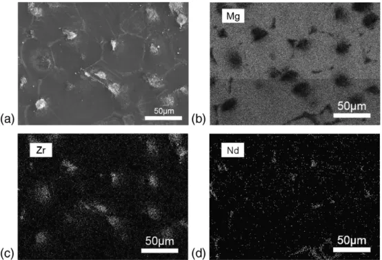
of agglomerates (white) in relief at the surface may be seen. The EDX analysis of this surface shows three main regions with dif-ferent compositions, one corresponding to the grains of magnesium, the second to the grain boundaries of neodymium, and the third one to the agglomerates (or compounds) of zirconium. The alloying elements gad-olinium and zinc are distributed homogeneously on the magnesium
alloy. The cross-section image (Fig. 2) of the surface of El21 alloy after
mechanical polishing and chemical etching shows the morphology of agglomerates rich on neodymium and zirconium.
3.2. Sol–gel coating without conversion film
First of all, during the preparation of sol–gel films by dip-coating,
an active production of gas at the surface of the El21 alloy samples was observed, when they were immersed in the sol. This indicates that a chemical reaction took place between the magnesium alloy
and the sol, reflecting the high degree of reactivity of this alloy.
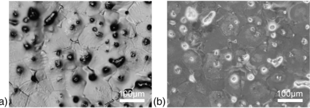
The hybrid coatings are naturally transparent, and to perform the observation of the coating surface by optical microscopy, the coated samples were gold-coated. It is possible to observe that the coating pre-sents a heterogeneous morphology, with several defects, with a size in
the range of 30–100 μm (Fig. 3a). The light-source of the optical
micro-scope consists on a ring that provides illumination of the sample. By switching between full-ring illumination and half-ring illumination, it
is possible to observe the objective at different angles of reflection,
since there is a change on the incidence angle of light. The images
shown inFig. 3a and b were taken at the same spot of the sample, and
they correspond to the surface of the hybrid sol–gel coating and the
El21 alloy surface, respectively.Fig. 3b clearly shows the magnesium
grains, and the neodymium and zirconium compounds (black points,
with light-gray surrounding area). Compared toFig. 3a, it may be seen
that the defects on the hybrid sol–gel coating are located at the same
position of the neodymium and zirconium compounds of the El21 alloy. The white arrow on the image marks the location of a defect on
the hybrid sol–gel film, which coincides with the location of the Nd
grain boundary on the substrate. Other defects can be also identified
on the sol–gel hybrid film, and their location coincides with the typical
position of Zr or Nd compounds.
A SEM image of the sample shows the morphology of the surface of
the hybrid sol–gel coating, where the presence of many nodules and
pits at the surface can be identified (Fig. 4). The cross-section of the
sample (Fig. 5) shows that the thickness of the coating is around
5μm. A difference of thickness on the coating between the
intra-granular zone of magnesium and the compounds of the alloy may be seen. It may be seen that the neodymium compounds remain at the same level of the magnesium grains. However, the yellow square on the left image indicates the position of a protuberance that emerges
Table 1
Chemical composition of the cast Elektron21 magnesium alloy used in this work. Elektron21
Element Nd Gd Zr Zn Other rare earths Mg Wt.% 3.1 1.7 1 0.5 b0.4 Balance
from the substrate, which disrupts the continuity of the hybrid sol–gel film.
Fig. 5b shows a SEM image obtained on a backscattered electron composition mode (BSE), in order to differentiate the present ele-ments: the magnesium substrate (light-gray), the hybrid coating (gray), the neodymium and zirconium compounds (white), and the
resin (dark-gray). The thickness of the hybridfilm is lower compared
to the rest of the surface at the location of the protuberance. Inside the hybrid coating, the existence of bubbles (black) that suggests
the presence of defects caused by occluded gas on the hybrid sol–
gel coating may be seen.Fig. 5c is a chemical mapping obtained by
EDX analysis at the same zone of the BSE image, showing that the white shape on the BSE image next to the protuberance suggests a neodymium compound, here in yellow. We note the presence of zir-conium in the region corresponding to the protuberance, with some smaller particles at the top of it and the discontinuity of the hybrid coating.
Despite the good leveling effect of the hybrid sol–gel coating, often
reported in the literature on several metallic alloys [33], on El21
casted alloy, these defects are not covered by the hybrid coating. Moreover, the presence of bubbles in the coating suggests a reactivity of the substrate with the sol during the immersion. These defects seem to have its origin on the microstructure of the cast El21 alloy and especially where the intermetallic compounds of neodymium
and zirconium-rich are located[43].
This work proposes the use of an intermediary conversion layer of
magnesium alloy, combined with a hybrid sol–gel film. This layer was
produced by the treatment of the samples with phosphoric acid, in order to form phosphate-based compounds, chemically more stable
than the magnesium metallic surface[8,10,11,14]. The characteristics
of the produced conversion layers are described hereinafter. 3.3. Conversion layer
The OCP of the El21 samples was recorded during immersion into
the H3PO4bath (Fig. 6). Between 0.5 and 3 g L−1of H3PO4, the
poten-tial slightly grows to positive values. On the other hand, with a
con-centration of 10 g L−1 of H3PO4, the potential considerably
increases during thefirst 30 s, followed by a steady increase to the
end of the immersion. Also, it may be underlined that the obtained
potential is higher at 10 g L−1 of H3PO4, which is related to the
growth of a thicker phosphate layer.
Fig. 7shows a SEM image of the surface of the samples after conversion treatment. The development of a conversion layer by
in-teraction with the magnesium-rich grains can be seen. The influence
of the microstructure and chemical composition of the alloy on the
formation of phosphate-basedfilms was also observed by W. Zhou
[10]for the AZ91D magnesium alloy. They showed that the
appear-ance of the phosphate layer is different in both cases: theα-phase
(rich on Mg) and theβ-phase (rich on Al). In the case of the El21
alloy, the magnesium region is much more reactive than the neodym-ium or zirconneodym-ium compounds. The composition of other phosphate conversion layers has been studied by other authors by EDS, establishing that they are mainly constituted of phosphates, oxides
and hydroxides[9,14].
Fig. 1. Observation by SEM of (a) the surface of the El21 magnesium alloy after acid etching with 20 g L−1of HNO3, for 2 min; EDX analysis of the surface: chemical mapping of
(b) Mg; (c) Nd and (d) Zr.
Fig. 2. SEM cross-section image of the El21 alloy after mechanical polishing and chem-ical etching with 20 g L−1of HNO3, for 2 min.
Like for the micrograph of the etched surface of the El21 alloy (Fig. 1a), whatever the H3PO4concentration of the conversion bath,
we can observe protuberances at the surface of grains corresponding to the presence of zirconium compound while the neodymium at
grain boundaries is only recovered by a thin conversionfilm. The
presence of an area rich in zirconium seems favorable to a strong local reactivity. It is important to notice that the concentration of
the bath H3PO4influences the morphology of the conversion layer.
For lower H3PO4concentrations, thefilm covers the magnesium grains
without apparent cracks. At concentrations superior to 3 g L−1the
ap-parition of cracks is observed, attributed to the higher thickness of the layer and to internal stresses generated during the drying of the
hydrat-ed conversionfilm. With a concentration of 10 g L−1 of H
3PO4, the
phosphate film shows wide cracks with an identical length to the
grain size. Cracks must be avoided when the purpose is to use this
con-versionfilm as a bond coat for additional coatings, like sol–gel coatings
or paints. Using lower concentrations of H3PO4decreases the number of
cracks.
The cross-section image of the samples in a BSE mode is shown in Fig. 7. The images allow to identify the magnesium grains (light-gray), the neodymium compounds (white), the phosphate
conversionfilm (gray), and the resin (dark-gray). Here, the
neodym-ium compounds seem attacked at a lower speed than the magnesneodym-ium grains, and the phosphate layer grew consuming the magnesium grains, as what commonly occurs in the chemical conversion phe-nomena. It may be seen that the thickness of the conversion layer
in-creases with the concentration of the H3PO4 bath.Fig. 8plots the
thickness of the conversion layer obtained at the different
concentra-tions of H3PO4tested (0.5, 1, 3 and 10 g L−1). This relationship
be-tween thickness and the H3PO4-concentration may be due to the
concentration of PO43−anions from the phosphoric acid available to
react with the Mg2+cations from the substrate. Both reactions, the
dissolution of the metallic substrate and the formation of the conver-sion layer are in competition. The reactions that form magnesium
phosphate, Mg3(PO4)2, have better performances and speed at higher
concentration of H3PO4 than the dissolution of the magnesium
substrate. This may explain the thickness increment of the phosphate conversion layer with the concentration of the phosphoric acid treatment.
3.4. Duplex system: conversion layer and sol–gel coating
During the dip coating of the El21 magnesium alloy with H3PO4
conversion layer in the sol, the emission of gas observed at the surface of the substrates, was in lower proportions compared to the samples without a conversion layer. Hence, the reactivity of the magnesium substrate was partially reduced by the presence of the phosphate
conversion layer.Fig. 9shows an optical image of the surface of the
duplex system: conversion layer/sol–gel coating. The surface of the
duplex system presents the same defects of the hybrid coating
pro-duced without a conversionfilm. The location of defects (lighting in
normal incidence, black areas inFig. 9a) coincides with the
emplace-ment of the zirconium and neodymium compounds of the El21 alloy
(white areas,Fig. 9b).
Fig. 10a shows a SEM image of the surface of the samples treated
with 10 g L−1 H3PO4 and coated with the hybrid film. It may be
seen that the sol–gel coating is transparent enough to electrons to
re-veal the microstructure of the underlying substrate.Fig. 10b shows a
cross-section of this system. The conversion layer is around 2μm
thick, and the hybrid coating 5μm thick. Likewise, the phosphate
film presents many cracks, in accordance with the previous
observa-tions (Fig. 7) and the hybrid coating seems tofill the discontinuities
of the conversion film. However, the auto-leveling effect of the
dip-coating process is not confirmed here, since the neodymium
com-pounds and the zirconium ones appear in relief in respect to the rest of the coating.
3.5. Electrochemical measurements 3.5.1. Open circuit potential
Fig. 11shows the open circuit potential for the samples recorded during the immersion time in the 0.05 M NaCl corrosive solution.
Fig. 3. Optical microscope images of the sol–gel coating applied on the El21 cast alloy after acid etching. (a) Normal mode; (b) light-shift mode.
The curves correspond to the bare substrate of El21, the hybridfilm
and the duplex system: conversion layer (10 g L−1 of H3PO4) +
-hybridfilm.
During thefirst minutes of immersion, the potential of bare El21
substrate becomes strongly negative. This phenomenon results from the depassivation of magnesium by dissolution of the natural oxidized layer present at the surface of the samples. After that, it becomes nobler with time, in reason of the natural passive layer generated at the surface by the reaction between the alloy and the electrolyte. This passive layer,
mainly constituted of magnesium oxide and hydroxide[1,44],
tempo-rarily delays the dissolution rate of the metallic substrate and offers a primary protection against corrosion.
On the other hand, the potential for the hybrid coated samples (with and without conversion layer) started with a more positive po-tential than the bare El21 substrate, and remains steady up to the end of the immersion. However, the potential oscillates in short periods of
time indicating that the interface substrate–electrolyte is subject to
disturbing phenomena, attributed to chemical reactions generated
between the magnesium substrate and the corrosive solution. This means that the barrier effect of the hybrid coating is limited, and
ex-hibits some permeability for the electrolyte. However, in thefirst time
of immersion (10 min), we can notice the nobler potential of the du-plex system than the single hybrid one.
3.5.2. Electrochemical impedance spectroscopy
3.5.2.1. Magnesium substrate. The EIS spectra for the uncoated El21
magnesium alloy after pretreatment are shown inFig. 12. Two time
constants can be observed in the Bode phase diagram (Fig. 12a), the
first located in the middle frequency range (15 Hz), and the second
one in the low frequency region (126 mHz). Correa et al.[37]propose
an interpretation of similar diagrams obtained for the AZ91 magnesium alloy. On his work, two time constants appear at the same range of
fre-quencies, one at 144 Hz, and the second at 388 mHz. Thefirst time
con-stant is associated to the passivefilm of the substrate, as it shows a
capacitive character due to its phase angle. In addition, thefilm does
not cover the entire surface of the substrate which can induce a faradic process. This layer is mainly composed of magnesium oxide and
hy-droxide[44,45]. The time constant at low frequency is considered as a
resistive behavior created by the corrosion process.
A different interpretation indicates that the time constant located in the middle frequency range (~10 Hz) is attributed to the capacitance of the electrochemical double layer at the interface metal/electrolyte. In fact, the presence of a time constant in the high frequency range (20 kHz), which increases its phase angle with the immersion time, is
attributed to the growth of the Mg(OH)2film[46].
Nevertheless, the obtained Bode phase diagrams on this work do not exhibit a time constant in the high frequency range, so the middle frequency time constant is considered as the capacitance of the
pas-sive layer. The impedance modulus (Fig. 12b) shows a slight increase
of the polarization resistance as a function of time at the low frequen-cy range, due to the development of the oxide/hydroxide layer and deposition of corrosion products. The value of the impedance modu-lus for the bare El21 alloy after 192 h of immersion in the corrosive
solution is 3.5 kohm·cm2.
Fig. 5. Cross-section SEM image of the El21 substrate coated with the hybrid sol–gel film, showing the precipitates of zirconium and neodymium. (a) 500× SEI image; (b) 1000× BEC image; (c) EDX analysis.
Fig. 6. OCP measurements during immersion of the El21 alloy in the H3PO4bath at
3.5.2.2. Duplex system: conversion layer and sol–gel coating.Fig. 13 shows the EIS plots for the El21 substrate coated different protection systems, after 192 h of immersion in the corrosive solution. The Bode
phase diagram (Fig. 13a) shows three time constants for all the
pro-tective systems, thefirst at high frequency (10 kHz), the second in
the low frequency region (100 Hz), and the third one in the low fre-quency range (0.1 Hz). The high frefre-quency time constant can be
at-tributed to the capacitance of the hybrid sol–gel coating. The second
time constant at middle frequency (100 Hz), may be ascribed to the
intermediate layer present at the interface metal/hybridfilm,
consti-tuted by both the phosphate conversion layer and corrosion products. The time constant at low frequency suggests the relaxation process of
absorbed species at the interface substrate/electrolyte[22,36,46,47].
It may be seen that the impedance modulus at low frequency is
inferior for the hybrid sol–gel coating compared to any of the duplex
systems, proving the beneficial effect of the conversion layer. Also, it
may be seen that the value of the impedance modulus is higher as
the concentration of H3PO4increases.
The duplex system treated with 10 g L−1of H3PO4shows the best
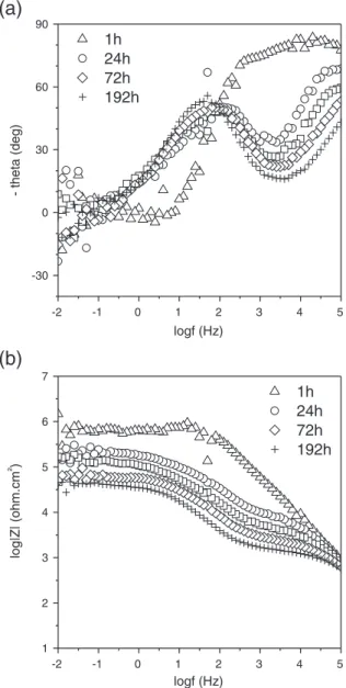
results on EIS (phase angle and impedance modulus) after 192 h of immersion, compared to the rest of the protection systems. The
Bode phase diagram (Fig. 14a) shows two time constants at the
be-ginning of the immersion (1 h), at high and low frequencies (10 kHz and 80 mHz, respectively). These capacitive responses can
be related to the sol–gel film, and the relaxation process of absorbed
species, respectively. After 24 h of immersion, the high frequency time constant considerably reduces its phase angle, related to electro-lyte incorporation that decreases the barrier properties of the hybrid
sol–gel coating. Likewise, the appearance of a second time constant at the middle frequency range (126 Hz) is attributed to the presence of an intermediate mixed layer, consisting of the conversion layer and
corrosion products, located between the hybrid sol–gel coating and
the magnesium substrate. Both time constants are visible on the fol-lowing hours of immersion, but the high frequency constant gradual-ly decreases its phase angle. The apparition of the second time constant after 24 h of immersion is afforded to the liquid take of the
sol–gel hybrid film which finally gets in contact with the metallic
sub-strate. The frequency range and the value of its phase angle are very similar to those of the bare substrate. This suggests that this interme-diate layer has the same morphological nature of the passive layer de-veloped by bare substrate, both consisting of a porous-ceramic layer. The impedance modulus shows a substantial reduction between 1 h and 24 h of immersion, slightly decreasing to the end of the immer-sion. After 192 h of immersion, the impedance modulus of the duplex
system conversion (10 g L−1)/hybridfilm is around 40 kohm·cm2.
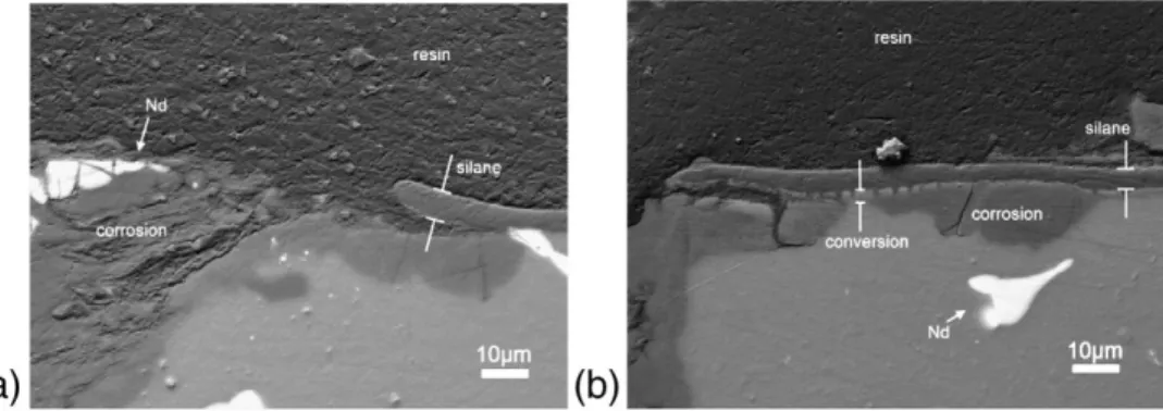
Fig. 15shows the cross-section SEM images on a BSE composition mode of the samples at the end of the immersion (192 h) in 0.05 M
NaCl.Fig. 15a corresponds to the El21 substrate coated with the
hy-brid sol–gel film. On the figure, it is possible to identify the
magne-sium substrate, the corrosion products and the hybrid sol–gel
coating. Some fragments of neodymium compounds inside the corro-sion products, which suggest that these neodymium compounds pos-sess a better resistance against corrosion than the magnesium grains may be seen. This is in good accordance with the results obtained by
Chang et al.[43], where the eutectic compound Mg12Nd of a similar
magnesium alloy (Mg, 3Nd, 0.2Zn, 0.4Zr, wt.%) remained unaffected
after 72 h of immersion in 5% NaCl. Moreover, the corrosion pits
grow under the hybrid sol–gel coating consuming mainly the
magne-sium grains, lifting up the hybrid sol–gel coating.
Fig. 15b shows duplex system at the end of the EIS tests. The
pres-ence of the conversion layer formed with 10 g L−1of H3PO4can be
identified, as well as the corrosion products that formed under the
duplex system. It is to notice that the conversion layer is in direct con-tact with the corrosion products, and both materials should have been exposed to the corrosive solution. However, only the metallic magnesium grains were transformed into corrosion products. This means that the conversion layer has a better chemical stability than the metallic magnesium grains, since it remained preserved after con-tact with the corrosive solution. These observations suggest that the conversion layer offers additional corrosion resistance and protection
combined with the hybrid sol–gel coating.
Usually, the corrosion pits appear at the spot of defects on the pro-tective coating, where the aggressive species have access to the sub-strate, progressively growing with time as they consume the
metallic substrate. The aggressiveness of Cl−ions for magnesium
al-loys is well known, which promotes the pitting corrosion[48].
Anoth-er typical way of pitting is the galvanic reactions created by the alloying phases of metallic substrates. The micro-galvanic cells per-form an exchange of charges at their boundaries, due to their poten-tial difference. When external agents, like liquids, get in contact with a metallic surface, the micro-galvanic cells promote the reaction be-tween the substrate and the corrosive agents.
Many works report the influence of the rare earth content on the
corrosion behavior of magnesium alloys. The addition of neodymium
or/and gadolinium modifies the microstructure of the magnesium
al-loys (AZ91D, AM50) reducing the portion ofβ-Mg17Al12phase, and so
the micro-galvanic couples with theα-Mg matrix[49,50]. Also, in the
case of the hot extruded AZ91 alloy, a decrease of the density of twins and dislocations on the microstructure is observed by increasing the
Nd content[51]. Furthermore, the anticorrosion properties of a cast
AZ91 alloy were substantially improved by the addition of rare earths (Ce, La, Nd and Pr), at the same time that the mechanical properties of
the alloy increased[52].
The influence of the zirconium content on a magnesium alloy has
been reported by Chang et al.[43]. The authors compare two different
alloys, one containing 0.4 wt.% of Zr, and the second one without Zr. The microstructure of the Zr containing alloys was similar to that of the El21 alloy, both presenting zirconium-rich cores at the center of the magnesium grains. Lower corrosion rates were obtained for these alloys, attributed to the formation of a more compact and
pro-tectivefilm, compared to those without zirconium.
However, the observations on this work show that the zirconium compounds of the El21 alloy represent an important source of
mor-phologic defects for the anticorrosion hybrid sol–gel treatment
(Fig. 3). The possible influence of these compounds may be based
on two reasons: thefirst, the height of the zirconium compounds
Fig. 8. Thickness of the phosphate conversion coating as a function of the H3PO4
concentration.
after acid pretreatment (Figs. 1 and 5) that obstructs the covering of the hybrid coating, and induces a partial or heterogeneous coverage area; the second may be attributed to a galvanic system between the zirconium compounds, the magnesium grains and the sol (when it is liquid), which generates a cathodic hydrogen evolution at this point and affects the surface of the hybrid coating during the conden-sation stage.
The presence of the conversion layer has a positive effect for
protec-tion afforded by the hybrid sol–gel treatment, due to the high values of
polarization resistance (log|Z|) obtained, compared to the single hybrid
coating. The low frequency resistance (or polarization resistance, Rp) is
considered as the global corrosion resistance of a protective system, like
paints or hybrid sol–gel coatings[22,35–37,39,46,53,54]. The resistance
of the lone hybrid coating decreases to lower values with time, meaning a faster loss of protective properties. A possible explanation is the
differ-ence of thickness between tested systems, the single sol–gel layer
(5μm), and the hybrid + conversion layer (7 μm). In the case of
anticorrosion coatings, thickness is an important parameter, since it de-termines the distance that separates the substrate from the aggressive
environments. The hybrid coating offers afirst protection against
ag-gressive species, opposing a barrier effect to keep them off from the
sub-strate. However, hybrid sol–gel coatings present a certain degree of
porosity that limits their barrier properties[41,55], partially blocking
species with high mobility, like liquids. Thereby, the presence of a sec-ond layer within the substrate and the hybrid coating offers an
additional obstacle for the electrolytes, reducing the mobility of
corro-sive species. Furthermore, the compounds identified on the conversion
layers are more chemically stable than the metallic substrate, with gen-erally a high degree of insolubility in water.
Fig. 10. SEM image of the El21 magnesium alloy coated with both conversion layer and sol–gel film. The conversion layer was obtained with a 10 g L−1H
3PO4bath. (a) Top view of
the coating (SEI mode); (b) cross-section view (BSE mode).
Fig. 11. OCP measurement of the bare El21 substrate after acid etching, coated with the sol–gel film, and coated with both conversion layer and sol–gel film, immersed in 0.05 M NaCl.
(a)
-2 -1 0 1 2 3 4 5 -30 0 30 60 901h
24h
72h
192h
-theta (deg) logf (Hz)(b)
-2 -1 0 1 2 3 4 5 1 2 3 4 5 6 71h
24h
72h
192h
log|Z| (ohm.cm ²) logf (Hz)Fig. 12. Bode diagrams of the EIS spectra for the uncoated El21 magnesium alloy substrate after pretreatment, during immersion in 0.05 M NaCl.
4. Conclusions
In this study, an anticorrosion duplex system“conversion layer”/“hybrid
coating” to protect the El21 magnesium alloy is reported and evaluated.
Mor-phological and electrochemical aspects of the protective systems were analyzed by SEM and EIS techniques. The high reactivity of the El21 magne-sium alloy has been taken in evidence because a hydrogen gas production is observed when this alloy gets in contact with the sols. This phenomenon
may lead to the formation of defects at the surface of the sol–gel coating.
Nev-ertheless, the single hybrid coating has very interesting properties of anti-corrosion protection, as shown by the EIS results. After 192 h of immer-sion in the corrosive solution (0.05 M NaCl), the impedance modulus of the hybrid coating is superior to that of the bare El21 alloy. However, after
192 h, the protective effect of the hybrid sol–gel film disappears.
The addition of a phosphate based conversion layer before the sol–
gel coating increases the impedance value of resistance of the protective system, with optimal results when the surface of the alloy is pretreated
with 10 g L−1of H3PO4for 2 min. The impedance modulus of the
sur-face is higher than the single hybrid coating after 192 h of immersion in the corrosive solution.
Despite the enhancement of the protective properties of the
hy-brid sol–gel coating by the addition of an intermediate phosphate
based conversion layer, the surface of the El21 alloy is not regular,
and tends to form discontinuities on the hybrid sol–gel coating,
locat-ed at the spot of the neodymium and zirconium compounds. The
cross-section SEM images show that the hybrid sol–gel coating has
a lower thickness in these points, representing a weak point on the hybrid coating, offering inferior protection against corrosive species and representing a source of corrosion.
Acknowledgments
This work was carried out in the framework of the CARAIBE pro-ject. The FDA and the OSEO are gratefully acknowledged for the funding provided for this project. The authors would like to thank the partners of the project: Liebherr, Turbomeca, Eurocopter, Mecaprotec, Fondérie Messier and the Institut Carnot CIRIMAT. References
[1] M. Pourbaix, Atlas D'équilibres Électrochimiques, 1963, pp. 140–145.
[2] T. Takenaka, T. Ono, Y. Narazaki, Y. Naka, M. Kawakami, Electrochim. Acta 53 (2007) 117.
[3] Y.L. Cheng, T.W. Qin, H.M. Hui, H.M. Wang, Z. Zhang, Trans. Nonferrous Met. Soc. China 19 (2009) 517.
(a)
-2 -1 0 1 2 3 4 5 -30 0 30 60 90C(1gL
-1) + silane
C(3gL
-1) + silane
C(10gL
-1) + silane
El21 substrate
Single silane coating
C(0.5gL
-1) + silane
- theta (deg) logf (Hz)(b)
-2 -1 0 1 2 3 4 5 1 2 3 4 5 6 7 El21 substrate Single silane coating C(0.5gL-1) + silane C(1gL-1) + silane C(3gL-1) + silane C(10gL-1) + silane log|Z| (ohm.cm ²) logf (Hz)Fig. 13. Bode diagrams of the EIS spectra for the El21 substrate treated with different protection systems, after 192 h of immersion in 0.05 M NaCl.
(a)
-2 -1 0 1 2 3 4 5 -30 0 30 60 901h
24h
72h
192h
- theta (deg) logf (Hz)(b)
-2 -1 0 1 2 3 4 5 1 2 3 4 5 6 71h
24h
72h
192h
log|Z| (ohm.cm ²) logf (Hz)Fig. 14. Evolution of the EIS spectra of the El21 substrate coated with the duplex system conversion layer (10 g L−1)/sol–gel coating, during immersion in 0.05 M NaCl.
[4] Q. Wang, Y. Liu, S. Fang, Y. Song, D. Zhang, L. Zhang, C. Li, Mater. Charact. 61 (2010) 674.
[5] M.B. Kannan, W. Dietzel, C. Blawert, A. Atrens, P. Lyon, Mater. Sci. Eng., A 480 (2008) 529.
[6] J.E. Gray, B. Luan, J. Alloys Compd. 336 (2002) 88.
[7] R.G. Hu, S. Zhang, J.F. Bu, C.J. Lin, G.L. Song, Prog. Org. Coat. 73 (2012) 129.
[8] U.C. Nwaogu, C. Blawert, N. Scharnagl, W. Dietzel, K.U. Kainer, Corros. Sci. 51 (2009) 2544.
[9] Y. Zhu, G. Yu, B. Hu, X. Lei, H. Yi, J. Zhang, Appl. Surf. Sci. 256 (2010) 2988.
[10] W. Zhou, D. Shan, E.H. Han, W. Ke, Corros. Sci. 50 (2008) 329.
[11] Y. Cheng, H. Wu, Z. Chen, H. Wang, L. Li, Trans. Nonferrous Met. Soc. China 16 (2006) 1086.
[12] M. Zhao, S. Wu, P. An, J. Luo, Mater. Chem. Phys. 103 (2007) 475.
[13] F. Pan, X. Yang, D. Zhang, Appl. Surf. Sci. 255 (2009) 8363.
[14] M. Mosialek, G. Mordarski, P. Nowak, W. Simka, G. Nawrat, M. Hanke, R.P. Socha, J. Michalska, Surf. Coat. Technol. 206 (2011) 51.
[15] M. Zhao, S. Wu, J. Luo, Y. Fukuda, H. Nakae, Surf. Coat. Technol. 200 (2006) 5407.
[16] X. Wang, G. Yu, Y. Ouyang, X. He, J. Zhang, L. Ye, Trans. Nonferrous Met. Soc. China 19 (2009) 504.
[17] T.F. da Conceicao, N. Scharnagl, W. Dietzel, C. Blawert, K.U. Kainer, Thin Solid Films 518 (2010) 5209.
[18] X. Liu, Z. Liu, P. Liu, Y. Xiang, W. Hu, W. Ding, Trans. Nonferrous Met. Soc. China 20 (2010) 2185.
[19] T.F. da Conceicao, N. Scharnagl, W. Dietzel, D. Hoeche, K.U. Kainer, Corros. Sci. 53 (2011) 712.
[20] M. Turhan, R. Lynch, M. Killian, S. Virtanen, Electrochim. Acta 55 (2009) 250.
[21] H. Elsentriecy, K. Azumi, H. Konno, Surf. Coat. Technol. 202 (2007) 532.
[22] A. Zomorodian, F. Brusciotti, A. Fernandes, M.J. Carmezim, T. Moura e Silva, J.C.S. Fernandes, M.F. Montemor, Surf. Coat. Technol. 206 (2012) 4368.
[23] F. Brusciotti, D.V. Snihirova, H. Xue, M.F. Montemor, S.V. Lamaka, M.G.S. Ferreira, Corros. Sci. 67 (2013) 82.
[24] A.L. Rudd, C.B. Breslin, F. Mansfeld, Corros. Sci. 42 (2000) 275.
[25] K. Brunelli, M. Dabala, I. Calliari, M. Magrini, Corros. Sci. 47 (2005) 989.
[26] M.F. Montemor, A.M. Simões, M.G.S. Ferreira, M.J. Carmezim, Appl. Surf. Sci. 254 (2008) 1806.
[27] D. Hawke, D.L. Albright, Met. Finish. 93 (1995) 34.
[28] J. Liu, J.C. Berg, J. Mater. Chem. 17 (2007) 4430.
[29] T.L. Metroke, O. Kachurina, E.T. Knobbe, Prog. Org. Coat. 44 (2002) 295.
[30] M.L. Zheludkevich, R. Serra, G. Grundmeier, L.H. Yang, M.G.S. Ferreira, Surf. Coat. Technol. 200 (2006) 4040.
[31]R. Zandi-zand, A. Ershad-langroudi, A. Rahimi, Prog. Org. Coat. 53 (2005) 286.
[32]K.A. Yasakau, M.L. Zheludkevich, O.V. Karavai, M.G.S. Ferreira, Prog. Org. Coat. 63 (2008) 352.
[33]J.B. Cambon, F. Ansart, J.P. Bonino, V. Turq, Prog. Org. Coat. 75 (2012) 486.
[34]D. Wang, G.P. Bierwagen, Prog. Org. Coat. 64 (2009) 327.
[35]M.F. Montemor, M.G.S. Ferreira, Electrochim. Acta 52 (2007) 7486.
[36]S.V. Lamaka, G. Knörnschild, D.V. Snihirova, M.G. Taryba, M.L. Zheludkevich, M.G.S. Ferreira, Electrochim. Acta 55 (2009) 131.
[37]P.S. Correa, C.F. Malfatti, D.S. Azambuja, Prog. Org. Coat. 72 (2011) 739.
[38]V. Barranco, N. Carmona, J.C. Galvan, M. Grobelny, L. Kwiatkowsky, M.A. Villegas, Prog. Org. Coat. 68 (2010) 347.
[39]A.F. Galio, S.V. Lamaka, M.L. Zheludkevich, L.F. Dick, I.L. Müller, M.G.S. Ferreira, Surf. Coat. Technol. 204 (2010) 1479.
[40]F. Zucchi, V. Grassi, A. Frignani, C. Monticelli, G. Trabanelli, Surf. Coat. Technol. 200 (2006) 4136.
[41]F. Zucchi, A. Frignani, V. Grassi, A. Balbo, G. Trabanelli, Mater. Chem. Phys. 110 (2008) 263.
[42]V. Meiffren, K. Dumont, P. Lenormand, F. Ansart, S. Manov, Prog. Org. Coat. 71 (2011) 329.
[43]J.W. Chang, P.H. Fu, X.W. Guo, L.M. Peng, W.J. Ding, Corros. Sci. 49 (2007) 2612.
[44]G. Baril, N. Pebere, Corros. Sci. 43 (2001) 471.
[45]G. Galicia, N. Pebere, B. Tribollet, V. Vivier, Corros. Sci. 51 (2009) 1789.
[46]S.V. Lamaka, M.F. Montemor, A.F. Galio, M.L. Zheludkevich, C. Trinidade, L.F. Dick, M.G.S. Ferreira, Electrochim. Acta 53 (2008) 4773.
[47]P.C. Banerjee, R.K.S. Raman, Electrochim. Acta 56 (2011) 3790.
[48]L. Yang, Y. Wei, L. Hou, D. Zhang, Corros. Sci. 52 (2010) 345.
[49]R. Arrabal, A. Pardo, M.C. Merino, M. Mohedano, P. Casajús, K. Paucar, G. Garcés, Corros. Sci. 55 (2012) 301.
[50]R. Arrabal, E. Matykina, A. Pardo, M.C. Merino, K. Paucar, M. Mohedano, P. Casajús, Corros. Sci. 55 (2012) 351.
[51]T. Zhang, G. Meng, Y. Shao, Z. Cui, F. Wang, Corros. Sci. (2011) 2934.
[52]G. Pettersen, H. Westengen, R. Hoier, O. Lohne, Mater. Sci. Eng., A 207 (1996) 115.
[53]A.L.K. Tan, A.M. Soutar, I.F. Annergren, Y.N. Liu, Surf. Coat. Technol. 198 (2005) 478.
[54]A.N. Khramov, V.N. Balbyshev, L.S. Kasten, R.A. Mantz, Thin Solid Films 514 (2006) 174.
[55]F. Zucchi, A. Frignani, V. Grassi, G. Trabanelli, M. DalColle, Corros. Sci. 49 (2007) 1570.
Fig. 15. Cross-section SEM images on a BEC mode of the corrosion pits formed on the El21 alloy samples after 192 h of immersion in 0.05 M NaCl. (a) Single hybrid coating; (b) duplex system (10 g L−1H3PO4).