Publisher’s version / Version de l'éditeur:
Vous avez des questions? Nous pouvons vous aider. Pour communiquer directement avec un auteur, consultez la
première page de la revue dans laquelle son article a été publié afin de trouver ses coordonnées. Si vous n’arrivez pas à les repérer, communiquez avec nous à [email protected].
Questions? Contact the NRC Publications Archive team at
[email protected]. If you wish to email the authors directly, please see the first page of the publication for their contact information.
https://publications-cnrc.canada.ca/fra/droits
L’accès à ce site Web et l’utilisation de son contenu sont assujettis aux conditions présentées dans le site
LISEZ CES CONDITIONS ATTENTIVEMENT AVANT D’UTILISER CE SITE WEB.
Internal Report (National Research Council of Canada. Division of Building
Research), 1984-12-01
READ THESE TERMS AND CONDITIONS CAREFULLY BEFORE USING THIS WEBSITE. https://nrc-publications.canada.ca/eng/copyright
NRC Publications Archive Record / Notice des Archives des publications du CNRC :
https://nrc-publications.canada.ca/eng/view/object/?id=6173b0e1-dea8-41a6-a63a-c88c79ff0be0 https://publications-cnrc.canada.ca/fra/voir/objet/?id=6173b0e1-dea8-41a6-a63a-c88c79ff0be0
NRC Publications Archive
Archives des publications du CNRC
For the publisher’s version, please access the DOI link below./ Pour consulter la version de l’éditeur, utilisez le lien DOI ci-dessous.
https://doi.org/10.4224/40001314
Access and use of this website and the material on it are subject to the Terms and Conditions set forth at
Fire tests on reinforced concrete columns, speciments no. 2-7: phase II
me1
Ser
National Research Conseil national
,
Council Canada
de recherche Canada
PUB
'
F I R E TESTS ON REINFORCED CONCRETE COLUMNS SPECIMENS NO. 2-7, PHASE I1
by T.T. Lie, T.D. L i n and R. McGrath
ANALYZED
Private copy for:
NATIONAL RESEARCH COUNCIL OF CANADA DIVISION OF BUILDING RESEARCH
OBR INTERNAL REPORT NO. 495
FIRE TESTS ON REINFORCED CONCRETE COLUMNS SPECIMENS NO. 2-7, PHASE I1
by T . T . L i e , T.D. Lin and R. McGrath
ANALYZED
Checked by: T -7..
H
.
Approved by: L.W. Gold
Date: December 1 9 8 4Prepared for: Record Purposes
ABSTRACT
R e s u l t s of f i r e t e s t s on s i x r e i n f o r c e d c o n c r e t e columns a r e
given. These t e s t s a r e a p a r t of a s e r i e s of twelve t e s t s c a r r i e d out i n t h e second phase of a j o i n t s t u d y on t h e f i r e performance of c o n c r e t e columns by t h e N a t i o n a l Research C o u n c i l Canada and C o n s t r u c t i o n Technology L a b o r a t o r i e s , a d i v i s i o n of t h e P o r t l a n d Cement A s s o c i a t i o n . Two of t h e columns were made of normal weight, and two of h i g h s t r e n g t h , s i l i c e o u s a g g r e g a t e c o n c r e t e . Two columns were made of expanded s h a l e l i g h t w e i g h t a g g r e g a t e c o n c r e t e . These columns measured 305 x 305 mm (12 x 12 i n . ) i n c r o s s - s e c t i o n and 3,810 mm (12 f t 6 i n . ) long. The purpose of t h e t e s t s was t o s t u d y t h e e f f e c t s of r e s t r a i n t , c o n c r e t e s t r e n g t h , and a g g r e g a t e d e n s i t y on t h e f i r e r e s i s t a n c e of t h e columns.
FIRE TESTS ON REINFORCED CONCRETE COLUMNS SPECIMENS NO. 2-7, PHASE I1
T.
T.
Lie, T.D.
~ i n l and R. ~ c ~ r a t h ~Tests were carried out on a series of reinforced concrete columns as part of a multi-phase study to develop methods for the determination of the fire resistance of such columns. The study was a cooperative effort between the National Research Council Canada (NRCC) and Construction Technology Laboratories, a division of the Portland Cement Association (PCA). The second phase of the study involves the fire testing of 12 columns. The columns were designed and manufactured by PCA in Skokie, Illinois, and tested in the NRCC laboratories in Ottawa.
This report describes tests on columns 2, 3, 4 , 5,
6
and7
of the second phase study. Columns 2 and 3 were tested to study the effect of restraint, columns4
and 5, the effect of high strength and columns6
and 7, the effect of use of lightweight aggregate concrete on the fire resistance of the columns. Column1,
which was constructed together with columns 2 and 3 for the study of the effect of restraint, was not tested because the tests on columns 2 and 3 provided sufficient information.Only test results will be given in this report. The results will be analysed later, and discussed in subsequent papers.
TEST SPECIMENS
The specimens consisted of square tied reinforced concrete columns. Columns 2 and 3 were made of normal weight concrete, and columns
4
and5
of high strength concrete, all made with siliceous aggregate. Columns6
and 7 were made with expanded shale lightweight aggregate. Details of thespecimens and their fabrication are given below.
Dimensions
Section size: 305 x 305 mm (12 x 12 in.) Height: 3810 mm (12 ft 6 in.)
Materials
Cement
Type I cement, a general purpose cement for the construction of reinforced concrete structures, was used.
lportland Cement Association, Skokie, Illinois.
Aggregates
Normal weight aggregates: Siliceous sand and gravel from Eau Claire, Wisconsin. The maximum size of the aggregate was 19 mm ( f in.). The gradation curves are shown in Fig.
1.
Petrographic information on the aggregate, obtained according to ASTM C295-79, is given in Table1.
Lightweight aggregates: The fine aggregate was siliceous sand from Eau Claire, Wisconsin. The coarse aggregate consisted of Solite expanded shale from North Carolina. The gradation curves of the aggregates are shown in Fig. 2. Petrographic information on the fine aggregate, obtained according to ASTM ~295-79,l is given in Table 1 (No.
4
to No. 200 sieve mesh size). A sieve analysis of the coarse shale aggregate is given in Table 2.Physical properties of aggregates
Normal weight aggregates: Specific gravity of sand (2.63); specific gravity of gravel (2.57); moisture content of sand (4.0%); moisture content of gravel (1.0%); saturated surface dry unit weight of gravel (1678 kg/m3)
(104.9 lb/ft3); fineness modulus of fine aggregate (2.96); fineness modulus of coarse aggregate (1.73).
Lightweight aggregates: Specific gravity of sand (2.63); specific gravity of shale (1.36); moisture content of sand (3.0%); moisture content of shale (7.6%); saturated surface dry unit weight of shale (23.4 kg/m3) (1.46 lb/ft3); fineness modulus of fine aggregate (3.00); fineness modulus of coarse aggregate (1.73).
Steel reinforcement
Deformed 25M (No. 8) longitudinal reinforcing bars and 10M (No. 3) ties, meeting the requirements of ASTM Designation ~615-80,2 were used. The yield stress of the 25M bars was 443.7 MPa (64.3 ksi) and that of the 10M bars, 426.5 MPa (61.8 ksi). The ultimate strengths of the 25M and 10M bars were 730 MPa (105.8 ksi) and 671 MPa (97 ksi), respectively.
Concrete mixes
The concrete mixes were designed to produce two normal weight concretes of 34.5 MPa (5000 psi) and 55 MPa (8000 psi) strength, and a lightweight concrete of 34.5 MPa (5000 psi) strength. The concretes were not
air-entrained.
Admixtures were added to produce the high strength and the lightweight concrete. Batch quantities are given in Table 3 and measured properties of the fresh concrete are given in Table
4.
Fabrication Casting
The columns were cast in specially designed forms. At the start of casting, the front of the form was left open for depositing fresh concrete. A small internal vibrator was applied to consolidate the concrete. As
tightly bolted to the form to avoid possible moisture leaks. Lifting hooks were embedded on opposite sides of the test specimens 800 mm (2 ft 73 in.) from the top of the column. A brass tubing humidity well3 with an inner diameter of
4
mm (5132 in.) was positioned at mid-height of the column for measuring internal concrete relative humidity at mid-depth.Reinforcing cage
The reinforcing cage was assembled by welding each end of four
longitudinal main reinforcing bars to a steel end plate. The bars were cut to 3800 mm (12 ft 53 in.) and machined at both ends, for a length of 19 mm
(a
in.) to a diameter of 12.7 mm( f
in.). Figure 3 shows details of the finished bars.* The dimensions of the end plates were 533 x 533 x 25 mm (21 x 21 x 1 in.). In each corner of the plate, 20.6 mm holes (13116 in.) were drilled to accommodate the longitudinal bars. The centers of the holes were spaced 92.1 mm (3 518 in.) from the centerlines of the plates. In this way a column was obtained with a section of 305 x 305mm
(12 x 12 in.) and a cover of 47.6 mm (1 718 in.) to the main reinforcing bars and 38.1 mm(13 in.) to the stirrups. The main bars and stirrups were tied together to complete the steel cage which, including the steel plates, was 3810 mm (12 ft 6 in.) long.
Welding
The provisions of
AWS
Designation ~12.1-754 were followed when welding plates and bars. These members were preheated with a propane torch to 288'C (550°F), to prevent brittle failure during welding. The side fillet weld was done around bars on the inner face of the bottom plate. McKay E10018-D2 and DYTRON-579 welding rods were used. Both types of welding rods have tensile strength of 834.9 MPa (121000
psi). Mild-steel welding rods were used to fill up the 6 mm(a
in.) deep holes on the outer faces of the plate. The rough surfaces of the welded joints on the outer face of the plate were ground to a smooth finish.The welding of the top steel plate was done after the casting of the columns. Before positioning the top plate, a 6 mm ($ in.) layer of mortar was spread over the top of the column to ensure good contact between steel
and concrete. The mortar was made of one part cement and three parts siliceous sand. Using the same procedure as for the bottom plate, the top plate was welded on the outer side to the bars and smoothed.
Curing
The concrete was cured in the column formwork for 7 days, at 21 to 24OC (70 to 75'F). The forms were then stripped and the columns conditioned in an atmosphere controlled at 21 to 24'C and 30 to 40% relative humidity.
The columns were transported in February 1982, about a year after their fabrication, from PCA, Skokie to NRCC, Ottawa. The columns were kept in the NRCC laboratory in an atmosphere of about 20°C (68°F) and 50%
R.H.,
untilthey were tested.
*Metric measurements in the figures and text have been converted from the original imperial measurements and rounded off to the nearest millimetre (except in Figure 5).
1
ThermocouplesButt-welded chromel-alumel thermocouples with a thickness of 0.912 mm (0.359 in.) were used to make thermocouple frames for measuring concrete temperatures at different locations in the mid-height section of the columns. Each frame consisted of a number of thermocouples tied to steel rods that were firmly secured to the main reinforcing bars. The
thermocouples were arranged to measure temperatures along the whole length of a centerline and a diagonal of the section. The location of the
thermocouples in the concrete and their numbering are shown in Figs.
4
and
5.
In addition, a number of thermocouples were mounted on the reinforcing steel bars and ties. The locations of the thermocouples on the steel are shown in Fig.
6
and in more detail in Fig.7.
All thermocouples were installed in such a way that the wire followed an isotherm for at least 12.7 mm
(1
in.) from the junction.Test Apparatus
The test was carried out by exposing the columns to heat in a furnace specially built for testing loaded columns and walls. The test furnace was designed to produce the conditions to which a member might be exposed during a fire, i.e. temperatures, structural loads, and heat transfer. It consists of a steel framework supported by four steel columns, with the furnace
chamber inside the framework (Fig. 8). The characteristics and
instrumentation of the furnace are described in detail in reference
5.
Only a brief description of the furnace and the main components will be given here.Loading Device
Three hydraulic jacks produce forces along the three principal axes. The jack acting along the axis of the test column is located at the bottom of the furnace chamber. The plate on top of this jack can be used as a platform to which the column can be attached.
Furnace Chamber
The furnace chamber has a floor area of 2642 x 2642 mm (8 ft 8 in. x
8 ft
8
in.) and is 3048 mm (10 ft) high. The interior faces of the chamber are lined with insulating materials that will efficiently transfer heat to the specimen. There are 32 propane gas burners in the furnace chamber, arranged in eight columns containing four burners each. The total capacity of the burners is 4700 kW (16 million Btu/h). Each burner can be adjusted individually, which allows for a high degree of temperature uniformity in the furnace chamber. The pressure in the furnace chamber is alsoadjustable. It was set somewhat lower than atmospheric pressure. Instrumentation
The furnace temperatures are measured with the aid of eight
chromel-alumel thermcouples. The junction of each thermocouple was located 305 mm (1 ft) from the test specimen, at various heights. Two thermocouples
were placed o p p o s i t e each o t h e r a t i n t e r v a l s of 610 mm ( 2 f t ) a l o n g t h e h e i g h t of t h e f u r n a c e chamber. The l o c a t i o n of t h e i r j u n c t i o n s and t h e i r numbering a r e shown i n Fig. 9. Thermocouples 4 and 6 were l o c a t e d a t a h e i g h t of 610 mm (2 f t ) from t h e f l o o r , thermocouples 2 and 8 a t 1220 mm ( 4 f t ) , thermocouples 3 and 5 a t 1830 mm ( 6 f t ) and thermocouples 1 and 7 a t 2440 mm ( 8 f t ) . The t e m p e r a t u r e s measured by t h e thermocouples a r e a v e r a g e d a u t o m a t i c a l l y and t h e a v e r a g e t e m p e r a t u r e used a s t h e c r i t e r i o n f o r
c o n t r o l l i n g t h e f u r n a c e temperature.
The l o a d s a r e c o n t r o l l e d and measured u s i n g p r e s s u r e t r a n s d u c e r s . The accuracy of c o n t r o l l i n g and measuring l o a d s
i s
about 20 icN ( 5 k i p s ) a t lower load l e v e l s and r e l a t i v e l y b e t t e r a t h i g h e r l o a d s .The a x i a l d e f o r m a t i o n of t h e t e s t specimen i s determined by measuring t h e d i s p l a c e m e n t of t h e j a c k t h a t s u p p o r t s t h e column. The displacement i s measured u s i n g t r a n s d u c e r s w i t h an a c c u r a c y of 0.002 mm (7.87 x i n . ) .
Test Conditions and Procedure
The columns were i n s t a l l e d i n t h e f u r n a c e by b o l t i n g t h e i r end p l a t e s t o a l o a d i n g head a t t h e t o p and a h y d r a u l i c j a c k a t t h e bottom. E i g h t 19 mm
(a
i n . ) b o l t s , e q u a l l y spaced around t h e column 63.5 mm (2f i n . ) from t h e s i d e s were used a t e a c h end.On t h e day of t h e t e s t , t h e m o i s t u r e c o n d i t i o n a t 152.4 mm (6 i n . ) from t h e s u r f a c e of t h e columns was measured w i t h a Monfore humidity gauge.
I n f o r m a t i o n on t h e m o i s t u r e c o n d i t i o n of t h e columns, t h e i r c a s t and t e s t d a t e , t h e s t r e n g t h of t h e c o n c r e t e s and t h e l o a d s t o which t h e columns were s u b j e c t e d , i s g i v e n i n Table 5. A l l l o a d s were c o n c e n t r i c and a p p l i e d 40 min b e f o r e t h e s t a r t of t h e t e s t .
I n t h o s e t e s t s on t h e e f f e c t of r e s t r a i n t of a x i a l t h e r m a l expansion o f t h e columns on t h e i r f i r e r e s i s t a n c e , t h e columns were f u l l y r e s t r a i n e d . This c o n d i t i o n was o b t a i n e d by i n i t i a l l y a p p l y i n g t h e maximum a l l o w a b l e l o a d on t h e columns and p r e v e n t i n g t h e i r e x p a n s i o n d u r i n g f i r e t e s t s by
c o n t r o l l i n g t h e l o a d . The maximum a l l o w a b l e l o a d was determined a c c o r d i n g t o A C I 318-83,6 u s i n g a live-to-dead l o a d r a t i o of 0.4 and t h e a c t u a l c y l i n d e r s t r e n g t h of t h e c o n c r e t e on t h e t e s t d a t e .
The column l e n g t h s were measured w i t h d i f f e r e n t i a l t r a n s d u c e r s ,
a t t a c h e d t o t h e column f u r n a c e frame, one a t t h e bottom l e v e l and one a t t h e t o p l e v e l of t h e columns. Inaccuracy i n t h e l e n g t h measurements, due t o d e f o r m a t i o n s of t h e column f u r n a c e s t r u c t u r a l frame, was avoided by
measuring t h e s e deformations with t h e a i d of s t r a i n gauges, and compensating t h e column l e n g t h s a c c o r d i n g l y . The l e n g t h s of t h e columns were k e p t
c o n s t a n t u n t i l t h e l o a d , which i n c r e a s e s i n i t i a l l y b u t reduces l a t e r w i t h r e d u c t i o n of t h e column s t r e n g t h , had r e t u r n e d t o i t s o r i g i n a l v a l u e . A t
t h i s p o i n t t h e l o a d was k e p t c o n s t a n t u n t i l t h e column f a i l e d .
I n a l l t e s t s t h e columns were exposed t o h e a t i n g c o n t r o l l e d s o t h a t t h e a v e r a g e t e m p e r a t u r e i n t h e f u r n a c e t o l l o w e d a s c l o s e l y a s p o s s i b l e t h e
A S T M - E ~ ~ ~ ~ o r ULC-~101~ s t a n d a r d temperature-time c u r v e . T h i s c u r v e can be approximately d e s c r i b e d by t h e f o l l o w i n g e q u a t i o n :
where Tf = t e m p e r a t u r e i n O C , and
r
= t i m e i n hwhere Tf = t e m p e r a t u r e i n OF.
During t h e t e s t s , t e m p e r a t u r e s i n t h e f u r n a c e and i n t h e columns were measured a t t h e l o c a t i o n s d e s c r i b e d e a r l i e r . The a x i a l s t r a i n s of t h e columns were a l s o measured. The columns were regarded t o have f a i l e d and t h e t e s t s were t e r m i n a t e d , when t h e h y d r a u l i c j a c k , which had a maximum speed of 76 mm/min ( 3 i n . / m i n ) , c o u l d no l o n g e r m a i n t a i n t h e a p p l i e d l o a d .
TEST RESULTS
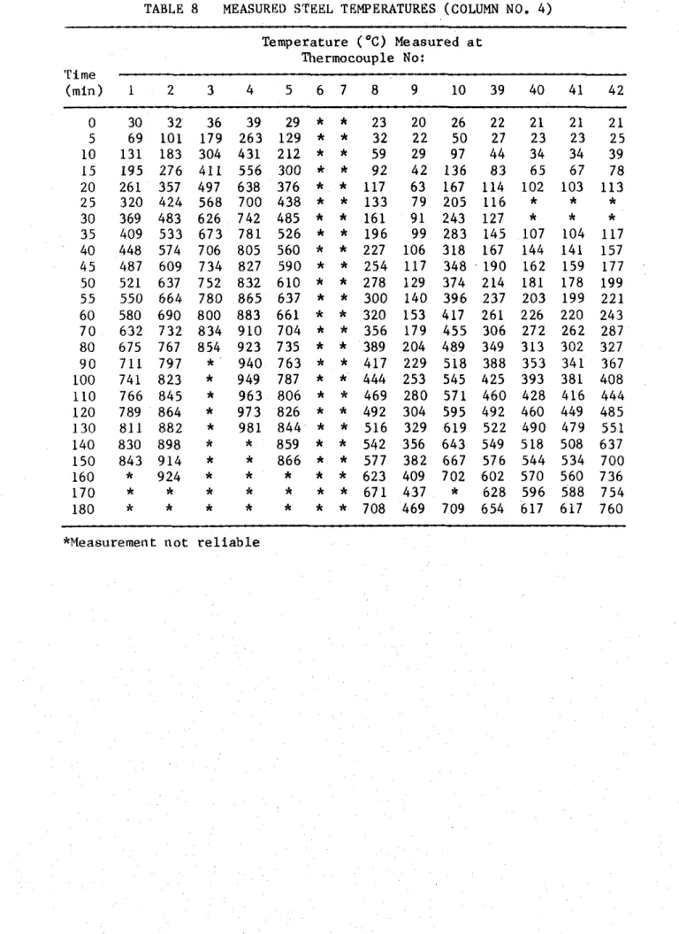
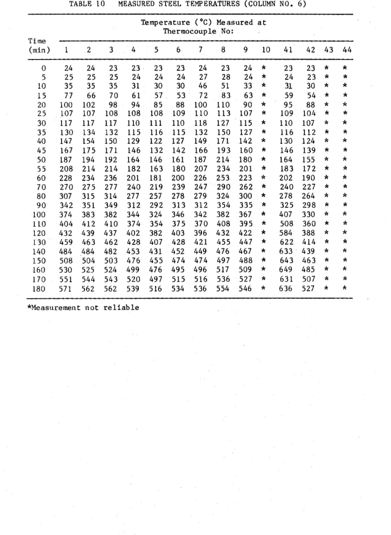
Measured Temperatures
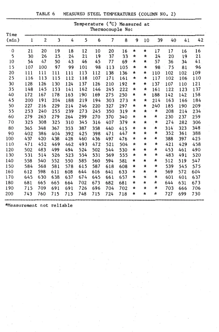
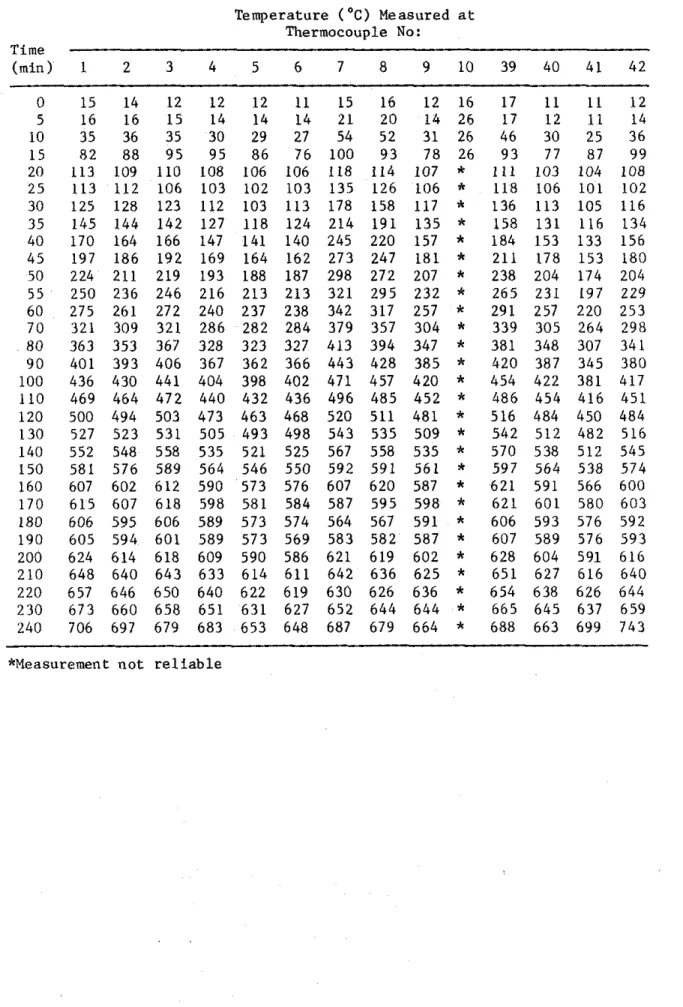
Tables 6-11 p r o v i d e measured s t e e l t e m p e r a t u r e s f o r columns 2-7 a t v a r i o u s t e s t times. The measured c o n c r e t e t e m p e r a t u r e s a r e g i v e n i n T a b l e s 12-17.
Table 18 g i v e s t h e measured a v e r a g e f u r n a c e t e m p e r a t u r e s f o r columns 2-7.
Measured Deformations and Loads
The measured a x i a l d e f o r m a t i o n s and a p p l i e d l o a d s d u r i n g t h e t e s t s of columns 2 and 3, under f u l l a x i a l r e s t r a i n t , a r e g i v e n i n T a b l e s 19 and 20. The measured a x i a l d e f o r m a t i o n s d u r i n g t h e t e s t s of columns 4 , 5 , 6 and 7 , which were t e s t e d under a c o n s t a n t l o a d , a r e g i v e n i n T a b l e 21.
Observations
Column No. 2 T e s t i n g time H r :Min 0:00 F i r e s t a r t e d a f t e r s u b j e c t i n g t h e column t o a p r e l o a d of I044 kN (235 k i p s ) f o r 40 minutes.0:20 One o r two h a i r l i n e c r a c k s on e a c h f a c e of t h e column. The a p p l i e d load reached a maximum of 2049 kN ( 4 6 1 k i p s ) .
0:35 Cracks on e a s t f a c e e x t e n d e d t o 150 mm (6 i n . ) l o n g and 1 mm
(1132 i n . ) wide.
l : 0 0 No new c r a c k s developed i n t h e l a s t 25 minutes.
1:20 Cracks a t t h e lower p a r t of t h e e a s t f a c e s l i g h t l y extended. Some were a b o u t 460 mm (18 i n . ) long. Fig. 1 0 shows t h e c r a c k s on f o u r s i d e s of t h e column.
2:00 A l l c r a c k s remained r e l a t i v e l y s t a b l e d u r i n g t h e l a s t 40 minutes. The a p p l i e d l o a d was about 1640 kN (370 k i p s ) .
2:15 Cracks on east face open up. The largest crack was about 650 mm (26 in.) long and 10 mm (318 in.) wide.
2:30 Most cracks enlarged noticeably.
2:50 The applied load reached the initial value of 1044 kN (235 kips), and was held constant from this point on. The column began to shorten. 2:56 The widest crack on the east face was about 20
mm
( 2
in.)3:15 Cracks on east, south and north sides widened, some to nearly 25 mm 1 in.. The column shortened about 3 mm.
3:21 The test column failed in compression.
Failure of the column in this test was due to crushing of the concrete and buckling of the main steel bars. Fig. 11 shows the column after the test and a close-up of the part of the column that failed.
Column No. 3 Test time Hr :Min
0:00 Fire started after subjecting the column to a preload of 916 kN
(206 kips) for
40
minutes.0:35 One or two hairline cracks at mid-height on each face of the column. The applied load reached a maximum of 1914 kN (431 kips).
1:00 All cracks had extended and widened. The largest crack, which was about 450 mm long and
2
mm wide, was observed on the south face of the column. Fig. 12 shows the cracks on four sides of the column. These crack patterns remained relatively stable until about a half hour before the end of the test.2:31 Sudden opening of laboratory door triggered the safety shut-down system of the furnace. The load at this point was about 1300 kN (293 kips). During the shut-down period the applied load decreased aomewhat
.
2:52 The fire was restarted. The load had decreased to 1120 kN (252 kips) and was further controlled to follow a theoretically derived
relation,1° that gives the load needed to fully restrain the column as a function of time.
3:17 The safety system was again activated and the fire shut off. The load was 1103 kN (248 kips) at this time, and was kept constant until the restart of the fire.
3:30 The fire was restarted and the load was controlled to follow the computed load until it had decreased to the original value of 916 kN (206 kips).
3:35 The cracks in the column rapidly worsened. Some crack openings were 25-40 mm (1-li in.) wide.
3:45 The applied load reached the initial value of 916 kN (206 kips). At this point the load was kept constant. The column started to
contract.
4:02 The test column failed in compression. Fig. 13 shows the column after the fire test.
Column No. 4 T e s t time H r :Min 0:00 F i r e s t a r t e d a f t e r s u b j e c t i n g t h e column t o a p r e l o a d of 1178 icN (265 k i p s ) f o r 40 minutes. 1 : 0 0 A v e r t i c a l h a i r l i n e c r a c k a b o u t 100 mm ( 4 i n . ) l o n g developed 50 mm ( 2 i n . ) away from t h e e a s t c o r n e r of t h e s o u t h f a c e of t h e column. 1:30 The f i r s t h a i r l i n e c r a c k developed i n t o a 460 mm (18 i n . ) long c r a c k .
Cracks 50 t o 150 mm (2 t o 6 i n . ) long were s e e n on o t h e r column f a c e s , n e a r t h e mid-height of t h e column. Fig. 14 shows t h e c r a c k s on f o u r s i d e s of t h e column.
1:45 A l l c r a c k s extended. Some were about 600 mm (2 f t ) long.
2:20 The c r a c k s i t u a t i o n on t h e s o u t h f a c e became worse. The worst c r a c k was 750 mm ( 2 t f t ) long and 3 mm (118 i n . ) wide.
2:45 Maximum c r a c k opening i n c r e a s e d t o about 5 mm (3116 i n . ) wide. 3:15 Three 150 mm (6 i n . ) l o n g p a r a l l e l c r a c k s developed i n t h e upper
q u a r t e r p o i n t a r e a of t h e west column f a c e .
3:40 Cracks widened r a p i d l y ; t h e w o r s t opening was more t h a n 6 mm
(i
i n . ) .3:47 The column f a i l e d i n compression. Fig. 1 5 shows t h e column a f t e r t h e f i r e t e s t . Column No. 5 T e s t t i m e H r :Min 0:00 F i r e s t a r t e d a f t e r s u b j e c t i n g t h e column t o a p r e l o a d of 1067 kN (240 k i p s ) f o r 40 minutes. 1:00 A v e r t i c a l h a i r l i n e c r a c k a b o u t 100 mm ( 4 i n . ) l o n g on t h e s o u t h f a c e , approximately a t mid-height of t h e column.
1:20 The f i r s t c r a c k e x t e n d e d t o 360 mm (14 i n . ) i n l e n g t h . Cracks 50 t o 150 mm (2 t o 6 i n . ) i n l e n g t h were s e e n on t h e o t h e r column f a c e s , i n t h e mid-height a r e a s of t h e column. Fig. 16 shows t h e c r a c k s on f o u r f a c e s of t h e column.
1:45 A l l c r a c k s extended. Some were about 460 mm (18 i n . l o n g ) .
2:20 Cracking on t h e n o r t h f a c e i n c r e a s e s . The l a r g e s t c r a c k was 50 mm (2 i n . ) l o n g and 6 mm () i n . ) wide.
2:45 Maximum c r a c k w i d t h was about 6 mm
( f
i n . ).3:40 Cracks widened r a p i d l y . The w i d e s t opening was a b o u t 1 3 mm ( $ i n . )
3:54 The column f a i l e d i n compression. Fig. 17 shows t h e column a f t e r t h e f i r e t e s t . Column No. 6 T e s t Time Hr : M i n . .
-
. . . -. . 0:00 F i r e s t a r t e d a f t e r s u b j e c t i n g t h e column t o a p r e l o a d of 1076 kN (242 k i p s ) f o r 40 minutes. 1:00 No c r a c k s were v i s i b l e .1:40 Flue c r a c k s developed U I E easL aud s u u L l ~ races u l Llle LesL c u l u i u ~ ~ .
2:10 Crack on t h e e a s t f a c e of t h e column i n c r e a s e d i n l e n g t h t o 460 mm (18 i n . ) .
2:20 Maximum crack width on the east face of the column was about 3 mm 1 8 in.. Small cracks also developed on north and west faces. Fig. 18 shows the cracks on four faces of the column.
2:58 600 mm (2 ft) long cracks developed in the lower quarter of the column on east and south faces.
2:59 A corner piece of concrete about 750 mm (2f ft) long fell off the southeast corner around the lower quarter height of the column, exposing a main reinforcing bar directly to fire.
3:08 The column buckled and the test was terminated. Fig. 19 shows the column after the fire test.
Column No.
7
Test Time Hr : Min
0:00 Fire started after subjecting the column to a
-
-
reload
of 947 kN (213 kips).1:40
Fine crack developed on east face of the test column.2:20 Small cracks also developed on north, west and south faces.
3:40 Cracks on all four faces expanded to about 13 mm ( f in) wide but no
spalling of cover or exposure of rebar was observed (see Fig. 20). 4:19 The column failed in compression. Fig. 21 shows the column after the
fire test.
The results of the tests on the restraint columns (Nos.
2
and 3)indicated that restraint of axial thermal expansion has little influence on the fire resistance of the column. There was no significant difference between the fire resistance of these columns, tested fully restrained
against axial thermal expansion, and that of similar columns tested under a normal load.
The results of the tests on the high strength concrete columns (Nos. 4 and
5)
showed that an increase of about 40% in the concrete strength gives an increase of about 15% in fire resistance over a normal column subjected to the same applied load. The gain in fire resistance is smaller, however, if, due to the higher strength of the concrete, the load is increased to the maximum permitted by ACI 318-836 Building Code.The fire resistance of lightweight concrete column No. 6 was somewhat lower than that of similar columns made with siliceous normal weight
concrete. Falling off of a large piece of concrete from one corner of the column, and direct exposure of the main reinforcing bar to fire, might have. substantially reduced the fire resistance of the column. The fire
resistance of lightweight concrete column No. 7 was considerably higher than that of siliceous normal weight concrete columns.
10
REFERENCES
Standard Practice for Petrographic Examination of Aggregates for Concrete (1979). ASTM C295-79, American Society for Testing and Materials, Philadelphia, PA.
Standard Specification for Deformed and Plain Bullet-Steel Bars for Concrete Reinforcement (1980). ASTM A615-80, American Society for Testing and Materials, Philadelphia, PA.
Monfore,
G.E.
(1962). A Small Probe-Type Gaugesfor Measuring Relative Humidity. Journal of the PCA Research and Development Laboratories, Vol. 5, No.2.
Reinforcing Steel Welding Code (1975). AWS-D12.1-75, American Welding Society, Manlius, NY.
Lie, T.T. (1980). New Facility to Determine Fire Resistance of Columns, Canadian Journal of Civil Engineering, Vol. 7, No. 3. Building Code Requirements for Reinforced Concrete (1983). ACI Standard 318-83, American Concrete Institute, Detroit, MI.
Standard Methods of Fire Tests of Building Construction and Materials (1979). ANSIIASTM E119-79, American Society for Testing and Materials, Philadelphia, PA.
Standard Methods of Fire Endurance Tests of Building Construction and Materials (1980). ULC-S101-M1980. Underwriters' Laboratories of
Canada, Scarborough, Ontario.
Lie, T.T. and Harmathy, T.Z. (1972). A Numerical Procedure to
Calculate the Temperature of Protected Steel Columns Exposed to Fire. Fire Study No. 28, Division of Building Research, National Research Council Canada, Ottawa, NRCC 12535.
Lie, T.T., Lin,
T.D.,
Allen, D.E. and Abrams, M.S. (1984). Fire Resistance of Reinforced Concrete Columns, Division of Building Research, National Research Council Canada, Ottawa, NRCC 23065.TABLE 1 PETROGRAPHY OF SAND AN0 GRAVEL USED AS AGGREGATE
Composition of S i e v e F r a c t i o n , P e r c e n t on S i e v e of S i z e I n d i c a t e d P e r c e n t
Component Passing
1 9 m m 12.5mm 9.5mm 6 mm No. No. No. No. No. No. No. through
4 8 1 6 30 5 0 100 200 No. 200 G r a n i t e 37.9 32.9 25.5 31.3 27 .O 27.6 12.3 7.4 1.9 4.4 0.6
--
Q u a r t z i t e 21.6 29.2 34.8 24.6 24.5 20.0 12.3 12.6 10.9 3.1 2.2--
Quartz 6.3 3.1 4.9 4.8 5.5 18.8 52.2 62.0 73.1 79.5 74.2 92.0 Sandstone-Quartz Conglomerate 1.9 0.8 3.1 5.1 5.5 8-3--
--
--
--
--
--
Rhyolite-Dacite 13.9 6.2 2.2 5.1 7.2 4.1 0.8 2.6 1.6 0.8 0.9--
F e l d s p a r--
--
--
--
--
--
1.3 5 .O 6.6 5.0 10.8 4.0 D i o r i t e 1.9 1.4 3.1 1.8 1.2--
--
--
--
--
--
--
Gneiss-Schist 2.5 5.1 10.5 9 . 3 7.5 4.1 6.4 1.8 0.9 1.1 0.6--
B a s a l t 1.9 4.5 4 .O 3.9 6 -9 3.2 2.6 2.4 0.7--
0.3--
Mist. Igneous Rocks andC Opaque M i n e r a l s--
0.3 0.9 0.6 0.6 1.5 2.1 1.2 2.0 5.3 7.0 2.0P a r t i c l e Shape 19 t o 6 mm ( % I No. 4 t o No. 1 6 ( % ) No. 3 0 t o No. 200 (%)
Subrounded t o rounded 30 20 1 0
Subrounded t o s u b a n g u l a r 40 40 40
Angular 3 0 4 0 5 0
a
..
I r o n s t o n e , " made up of j a s p e r and h e m a t i t e , i s i n c l u d e d i n t h e c h e r t c l a s s i f i c a t i o n . b ~ n c l u d e s metagraywacke.he m i s c e l l a n e o u s i g n e o u s r o c k s were s e v e r e l y a l t e r e d and p o s i t i v e i d e n t i f i c a t i o n was imposible. The opaque m i n e r a l s o c c u r r e d i n t h e No. 50 and s m a l l e r s i e v e s i z e s and were l a r g e l y magnetite.
TABLE 2 SIEVE ANALYSIS OF COARSE SHALE AGGREGATE Weight R e t a i n e d on S i e v e of S i z e I n d i c a t e d Sieve Mesh S i z e P e r c e n t a g e Cumulative P e r c e n t a g e 19 mm 9.74 12.5 mm 45.24 9.5 mm 25.13 No. 4 18.89 PAN 1 .OO
TABLE 3 BATCH QUANTITIES
--
Q u a n t i t y i n Concrete kg/m3 ( l b / y d 3
S i l i c e o u s Agg. S i l i c e o u s Agg. Lightweight
Concrete Concrete Aggregate
Item (Normal S t r e n g t h ) (High S t r e n g t h ) Concrete
Cement 325 (546) 525 (883) 339 (570) Coarse Aggregate 1058 (1780) 972 (1635) 591 (996) Sand 874 (1470) 691 (1163) 829 (1395) Water 140 (236) 148 (249) 176 (296) Admixture: Darex
-
-
148 m l P o z z a l i t h-
5245ml
-
13
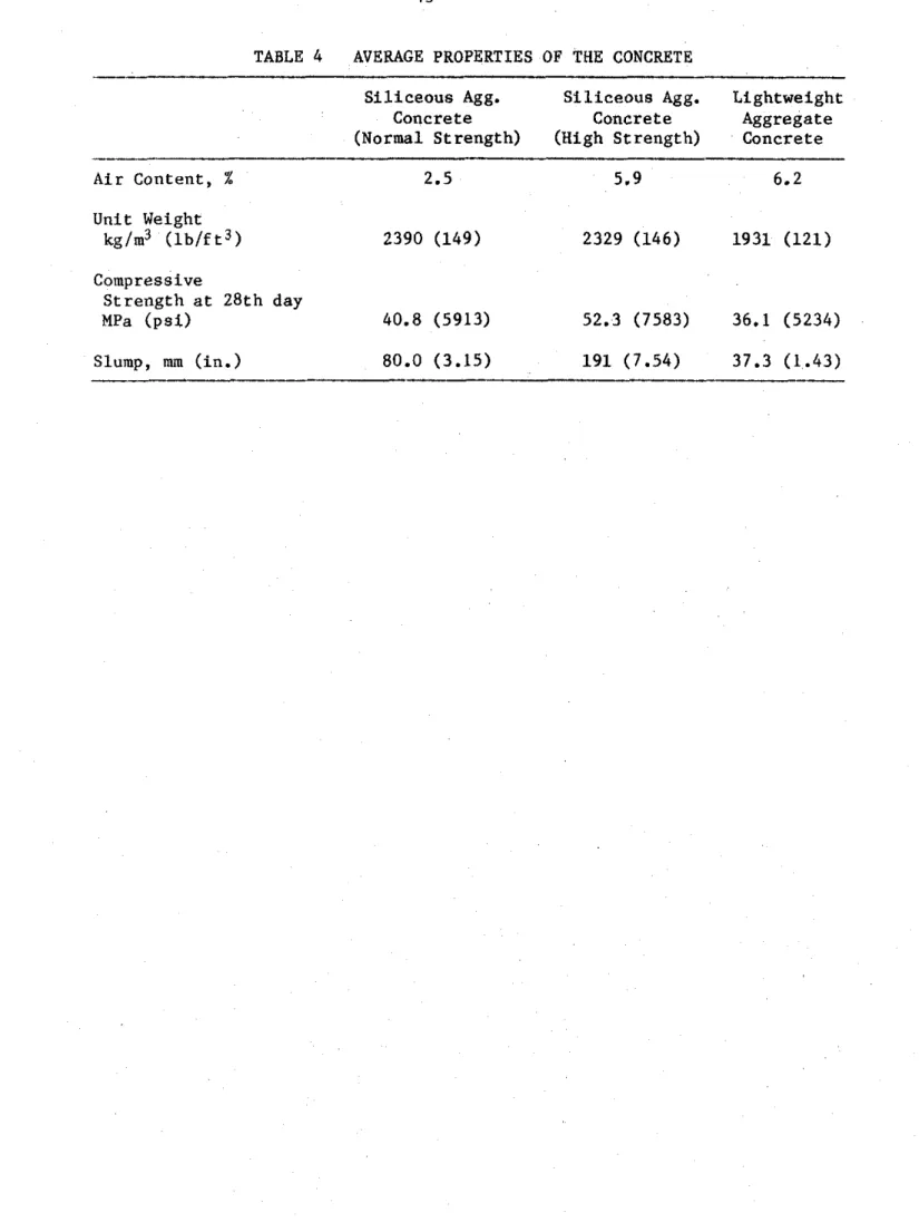
TABLE 4 AVERAGE PROPERTIES OF THE CONCRETE
S i l i c e o u s Agg. S i l i c e o u s Agg. Lightweight
Concrete Concrete Aggregate
(Normal Strength) (High Strength) Concrete
Air Content, X Unit Weight kg/m3 ( l b / f t 3 ) Compressive Strength a t 28th day MPa ( p s i ) Slump, mm ( i n . )
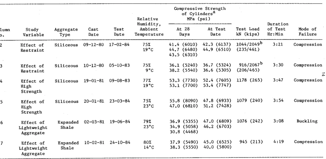
TABLE 5 SECOND PHASE COLUMN TEST SPECIMENS AND TEST RESULTS Compressive S t r e n g t h
of c y l i n d e r s a R e l a t i v e MPa ( p s i )
Humidity, D u r a t i o n
Column Study Aggregate Cast T e s t Ambient At 28 A t T e s t T e s t Load of T e s t Mode of No. V a r i a b l e Type Date Date Temperature Days Date kN ( k i p s ) Hr:Min F a i l u r e
2 E f f e c t of S i l i c e o u s 09-12-80 17-02-84 75% 41.4 (6010) 42.3 (6137) 1 0 4 4 1 2 0 4 9 ~ 3:21 Compression R e s t r a i n t 19°C 44.7 (6480) 44.9 (6510) (2351461) 43.5 (6310) 3 E f f e c t of S i l i c e o u s 10-12-80 05-10-83 75% 36.1 (5240) 36.7 (5324) 9 1 6 1 2 0 6 7 ~ 3 :30 Compression R e s t r a i n t 9OC 38.2 (5540) 36.6 (5305) (2061465) A 4 E f f e c t of S i l i c e o u s 19-01-81 09-08-83 77% 53.3 (7730) 52.4 (7605) 1178 (265) 3:47 Compression High 19°C 53.1 (7700) 53.4 (7747) 5 E f f e c t of S i l i c e o u s 20-01-81 23-03-84 75% 55.8 (8090) 47.8 (6933) 1079 (240) 3:54 Compression High 23°C 47.0 (6810) 51.2 (7428) 6 E f f e c t of Expanded 02-03-81 19-06-84 79% 36.9 (5355) 47.0 (6809) 1076 (242) 3:08 Buckling Lightweight S h a l e 23OC 34.9 (5058) 46.2 (6703) Aggregate 30.8 (4468) 7 E f f e c t of Expanded 10-02-81 24-10-84 80% 37.9 (5490) 45.0 (6525) 945 (213) 4:19 Compression Lightweight S h a l e 14OC 38.3 (5550) 40.0 (5800) Aggregate
a ~ e s u l t s of two o r more c y l i n d e r t e s t s are g i v e n
TABLE 6 MEASURED STEEL TEMPERATURES (COLUMN NO. 2) - Temperature ( O C ) Measured a t Thermocouple No: Time (min) 1 2 3 4 5 6 7 8 9 1 0 3 9 4 0 4 1 4 2 0 21 20 19 18 12 10 20 16
*
*
17 17 16 16 5 30 26 25 24 21 19 37 3 3*
*
24 20 19 21 10 54 47 50 43 46 45 77 69*
*
57 36 34 4 1 15 107 100 97 99 101 98 113 105*
*
98 75 8 1 9 6 20 111 111 111 111 25 116 113 115 112 30 128 126 130 124 35 148 145 153 141 40 172 167 178 163 45 200 191 204 188 50 227 216 229 214 55 253 240 255 239 60 279 263 279 264 70 325 308 325 310 80 365 348 367 353 9 0 402 386 404 392 100 437 420 438 428 110 471 452 469 462 120 502 483 499 494 130 531 514 526 523 140 558 540 552 550 150 584 568 581 578 160 612 598 611 608 170 6 4 5 630 638 637 180 681 665 665 664 190 715 709 691 691 200 743 760 715 713 *Measurement n o t r e l i a b l e16
TABLE 7 MEASURED STEEL TEMPERATURES (COLUMN NO. 3) Temperature ( ' C ) Measured a t
Thermocouple No: Time
(min) 1 2 3 4 5 6 7 8 9 10 39 40 41 4 2
TABLE 8 MEASURE0 STEEL TEMPERATURES (COLUMN NO. 4)
Temperature (OC) Measured a t
Thermocouple No: 'rime (min) 1 2 3 4 5 6 7 8 9 10 39 40 41 42 0 30 32 36 39 5 69 101 179 263 10 131 183 304 431 15 195 276 411 556 20 261 357 497 638 25 320 424 568 700 30 369 483 626 742 35 409 533 6 7 3 781 40 448 574 706 805 45 487 609 734 827 50 521 637 752 832 55 550 664 780 865 60 580 690 800 883 7 0 632 732 834 910 80 675 767 854 923 9 0 711 797
*
940 100 741 823*
949 110 766 845*
963 120 789 864*
973 130 811 882*
981 140 830 898*
x 150 843 914*
*
160*
924*
x 170*
x x x 180*
x x x "Measurement n o t r e l i a b l eTemperature ( O C ) Measured a t Thermocouple No: Time ( i n i n ) I 2 3 4 5 6 7 8 9 1 0 3 9 4 0 4 1 4 2 0 24 24 24 24 23 24 5 25 26 26 27 30 26 1 0 37 37 39 42 59 37 15 7 1 7 2 7 9 8 3 9 5 69 20 104 108 109 115 122 110 25 112 1 1 3 115 115 1 3 4 114 30 120 116 122 127 157 114 35 131 128 139 142 182 126 40 144 143 160 159 200 142 45 161 1 6 1 182 179 217 162 50 181 181 206 200 238 183 55 202 202 232 222 261 206 60 223 224 257 244 278 228 7 0 264 269 305 287 321 270 8 0 304 309 348 328 359 310 9 0 342 346 388 366 395 347 100 378 381 424 403 430 382 110 413 416 458 438 464 414 120 446 450 488 471 497 445 190 477 4 8 1 515 5 0 1 527 474 140 506 509 539 529 555 501 1 5 0 533 535 562 556 5 8 1 526 160 559 560 586 583 606 552 1 7 0 586 586 609 6 1 0 6 3 2 577 180 612 612 633 637 657 602 2 0 0 662 659 6 8 3 6 8 5 7 0 4 6 4 6 220 712 702 714 725 7 4 4 685 230 7 3 0 7 1 9 727 7 3 5 7 6 2 7 0 3 *Measurement n o t r e l i a b l e
TABLE 10 MEASURED STEEL TEMPERATURES (COLUMN N O . 6 ) Temperature ( " C ) Measured a t Thermocouple No: Time (min) 1 2 3 4 5 6 7 8 9 1 0 4 1 4 2 4 3 4 4 *Measurement not r e l i a b l e
TABLE 11 MEASURED STEEL TEMPERATURES (COLUMN NO. 7 ) Temperature ('C) Measured a t Thermocouple No: Time
-
(min) 1 2 3 4 5 6 7 8 9 1 0 1 1 1 2 0 18 24 16 15 13 13 17 14 16 22 18 16 5 19 24 17 16 14 14 24 19 16 22 144 89 10 29 16 29 24 24 20 48 40 25 22 253 162 15 65*
70 53 51 43 88 72 53 22 342 232 20 96 86 100 90 85 76 115 105 84 23 423 299 25 102 89 105 108 106 96 133 118 100 23 484 354 30 106 93 118 110 114 104 154 135 109 23 532 398 35 121 106 133 116 119 109 179 155 114 23 567 433 40 137 121 152 128 133 120 205 177 129 23 596 464 45 155 138 175 143 152 135 230 199 147 23 619 490 50 176 156 198 161 172 152 247 221 166 23 639 514 55 197 175 222 180 195 171 264 241 187 23 657 535 60 219 195 246 200 217 190 284 260 208 23 673 553 70 263 236 291 242 260 229 320 296 251 24 700 584 80 305 273 332 281 301 266 353 330 292 24 724 610 90 344 305 370 317 338 302 381 360 330*
746 634 100 379 335 403 350 372 336 407 386 364*
766 656 110 412 363 433 382 404 367 431 414 395*
785 676 120 443 388 462 415 434 396 454 439 425*
802 696 130 471 411 489 443 464 423 477 465 454*
819 714 140 496 433 514 469 491 449 499 489 481*
832 730 150 519 453 538 493 515 473 520 511 505*
847 745 160 540 474 559 513 537 496 543 532 529*
858 754 170 560 496 581 534 554 516 568 554 551*
872 769 180 579 517 601 554 573 536 591 575 573*
886 784 190 596 534 620 574 590 555 611 595 593*
896 797 200 613 553 638 594 608 573 631 613 612*
915 807 210 629 570 655 614 624 589 649 630 630*
917 808 220 645 586 671 632 640 606 666 647 647*
909 803 230 661 602 687 650 655 621 683 663 663*
883 794 240 675 616 701 668 670 636 698 678 678*
840 781 250 689 629 710 686 684 651 709 693 693*
796 769 255 696 636 711 694 690 658 711 700 700*
775 763 *Measurement n o t r e l i a b l eTABLE 1 2 CONCRETE TEMPERATURES MEASURED AT MID-HEIGHT (COLUMN NO. 2 ) Temperature ( O C ) Measured a t Thermocouple No:
Time (min) 11 1 2 1 3 14 15 16 17 18 19 20 21 22 2 3 24 25 26 27 28 29 30 31 32 33 34 35 36 37 38 0 21 18 1 8 18 1 8 19 19 19 18 17 17 18 21 23 22 20 18 1 8 18
*
18 1 8 17 17 17 18 24*
5 159 103 57 34 20 19 19 18 20 38 100 136 235 277 166 124 70 38 20*
18 1 8 20 37 86 131 233*
1 0 260 172 108 69 30 19 18 19 36 90 172 231 371 422 266 205 118 8 3 34*
18 18 36 94 155 235 388*
15 350 240 146 105 48 23 19 24 84 124 254 323 475 531 357 283 168 105 52*
19 24 91 120 231 330 497*
20 425 303 1 9 1 129 77 3 1 24 38 106 1 4 3 324 389 551 610 429 349 215 129 81*
23 37 98 165 301 403 571*
25 486 357 233 153 96 62 30 5 3 106 194 385 451 621 677 490 406 263 158 81*
34 47 102 216 364 466 637*
3 0 534 405 274 187 1 0 1 7 8 44 64 109 245 436 510 681 568 538 454 306 185 8 6*
45 58 105 269 420 520 692*
35 571 444 310 219 108 8 5 55 7 5 1 2 3 289 481 556*
587 573 493 342 211 95*
58 67 118 313 464 568 733*
4 0 595 475 342 248 120 90 6 3 8 4 140 328 521 598*
638 596 521 370 226 101*
73 77 134 346 502 610 757*
45 621 502 369 274 133 96 72 93 161 362 556 634*
703 620 545 394 261 105*
83 87 153 375 534 644 782*
5 0 648 528 394 297 144 1 0 1 83 1 0 3 1 8 3 391 592 665*
734 642 569 420 292 112*
*
98 174 399 564 677 805*
55 670 550 417 318 156 103 91 106 204 418 624*
*
748 663 593 445 321 123*
* *
* * *
* * *
6 0 688 571 437 337 170 107 9 8 111 225 441 649 694*
758 679 613 467 345 144*
* *
196 4 2 1 600 706 814*
2
70 723 607 473 373 200 117 108 127 265 482 693 734*
776 713 650 505 383 179*
* *
* * * * * *
8 0 751 640 504 405 231 132 1 1 8 1 6 5 303 527 730 752*
784 741 682 537 415 211* * * *
* *
*
*
*
90 777*
533 434 258 150 126 271 345 610 758 765*
773 761 716 566 446 245*
*
162 329 539 729 756* *
100 798*
560 461 2 8 3 1 6 8 135 382 429 679 776 775*
768 753 739 595 523 366* *
187 361 569 751 765* *
110 817*
585 486 317 197 146 444 532 714 787 783*
774 734 746 649 665 634* *
212 394 602 765 756*
*
1 2 0 845*
613 514 404 307 172 492 600 734 797 790*
775 737 758 715 726 725* *
251 445 645 775 749* *
130 820*
657 561 577 561 272 621 650 739 773 754*
750 750 765 742 739 747*
*
*
579 693 786 802* *
140 750*
713 662 687 697 547 711 696 728 742 729*
730 763 761 753 741 755*
*
*
691 725 796* *
*
150 735*
742 722 727 737 708 741 728 735 738 733*
736 769 759 753 749 764* * *
737 746 807* *
*
1 6 0 747*
759 742 732 752 741 746 744 743 745 740*
749 765 761 752 759 769* *
*
757 755 808*
* *
170 763*
773 754 741 760 755 749 758 757 760 748*
756 762 769 757 768 774* *
*
769 761* * * *
180 777*
781 764 750 759 759 755 769 771 771 7 5 5*
760 764 778 766 774 777* * *
772* * * * *
190 783*
785 772 760 758 760 752 775 774 764 761*
763 767 785 774 776 777*
*
*
767* *
* * *
200 768*
785 771 767 762 761 750 767 766 756 766*
758 773 788 782 780 774*
*
*
781*
*
*
*
*
*Measurement n o t r e l i a b l eTime ( m i d
-
0 5 10 15 20 25 30 35 40 45 50 55 60 70 8 0 90 100 110 120 130 140 150 160 170 180 190 200 210 220 2 30 240TABLE 1 3 CONCRETE TEMPERATURES MEASURED AT MID-HEIGHT (COLUMN NO. 3 ) Temperature (OC) Measured a t Thermocouple No:
TABLE 14 CONCRETE TEMPERATURES MEASURED AT MID-HEIGHT (COLUkfN NO. 4 ) Temperature (OC) Measured a t Thermocouple No:
Time (min) 11 12 1 3 14 15 16 17 1 8 19 20 21 22 23 24 25 26 27 28 29 30 31 32 33 34 35 36 37 38 0 29 28 26 24 21 19 19 19 22
*
25 23 22 22 22 22 23 23 21 19 19 18 21 25 30 32 36 48 5 136 96 56 34 23 20 19 20 24*
29 27 26 25 25 25 32 33 24 19 19 19 23 36 75 117 203 273 1 0 224 160 104 6 3 31 21 19 21 32*
46 41 40 42 42 36 58 59 34 20 19 20 31 73 138 200 336 424 15 315 229 139 94 47 23 20 25 60*
9 0 78 7 8 78 8 4 70 9 1 92 67 23 19 23 63 112 199 291 454 548 20 393 294 181 120 67 27 22 33 100*
117 114 111 113 1 1 3 99 117 115 106 30 21 32 105 135 264 362 540 634 25 460 355 226 146 1 O i 35 26 47 114*
124 116 115 115 114 113 134 138 111 37 25 4 1 115 164 323 417 605 698 30 514 408 266 1 7 1 104 47 32 58* *
136 1 2 1 124 121 121 116 159 1 6 3 116 47 31 5 3*
206 378 466 648 742 35 555 454 301 198 106 56 39 67 119*
156 135 140 136 136 127 193 189 127 57 39 6 3 115 261 433 518 695 780 40 586 490 333 225 116 65 48 76 132*
178 154 159 154 155 144 226 214 1 4 3 66 48 72 126 305 483 566 730 806 45 613 521 362 249 128 77 57 8 5 152*
202 177 180 175 177 165 256 237 161 74 56 79 140 344 525 609 752 827 50 631 544 386 271 14C 87 65 94 172*
227 201 201 1 9 8 202 187 283 259 182 8 3 64 87 157 377 5 6 1 642*
833 55 659 568 407 290 151 95 74 104 192*
251 226 224 220 226 211 307 280 204 91 72 95 175 406 593 671 731 864 6 0 6 8 3 589 427 308 164 1 0 3 8 4 1 1 4 213*
274 251 248 242 250 235 329 301 227 99 81 104 195 433 624 697*
879 70 717 627 464 342 191 116 101 131 252*
319 298 295 287 296 281 370 339 273 113 97 117 233 478 675 740 771 898 8 0 745 660 4 9 8 374 2 1 8 130 111 149 289*
359 342 339 330 340 324 405 374 317 129 106 134 269 517 716 776 791*
90 773 689 529 404 244 145 121 165 323*
396 380 381 370 380 364 438 407 357 136 114 149 305 553 749 806 804*
1 0 0 801 714 557 430 268 1 6 1 134 182 354*
431 416 418 408 418 401 467 438 395 150 121 168 340 587 778 8 3 3 812*
110 821 735 583 455 291 177 144 203 385*
463 451 453 444 454 435 496 467 431 174 139 204 377 622 795 853*
*
120 8 4 2 755 607 478 314 196 157 226 415*
493 482 486 477 488 466 521 4 9 5 464 194 155 320 436 671*
869*
*
130 860 776 630 502 339 217 173 257 446*
521 511 516 508 519 496 546 520 495 216 172 502 558 714* * *
*
140 876 795 654 528 364 240 192 3 0 5 486*
547 538 543 536 547 523 570 544 524 239 192 619 662 742*
*
*
*
150 892 813 677 554 392 269 216 368 534*
573 562 570 564 575 548 593 568 550 264 216 677 715 757* *
* *
1 6 0 908 8 2 1 700 5 8 1 419 326 244 425 582*
599 587 596 591 602 574 615 593 576 290 246 693 742 764*
*
*
*
170 920*
721 607 447 460 291 464 621*
624 613 622 617 628 599 636 617 602 315 290*
741 770*
*
* *
1 8 0 929*
737 631 474 594 405 481 657*
648 639 646 642 651 623 656 640 627 342 354* *
777*
* *
*
*Measurement n o t r e l i a b l eTABLE 15 CONCRETE TEMPERATURES MEASURED AT MID-HEIGHT (COLUMN NO. 5 ) T e m p e r a t u r e ('C) M e a s u r e d a t T h e r m o c o u p l e No: Time (min) 11 12 13 14 15 16 17 18 19 20 21 22 23 24 25 26 27 28 29 31 32 33 34 35 36 37 38 0 26 24 23 23 23 22 22 22 23 23 24 25 28 34 26 24 23 23 22 23 22 23 23 23 23 26 31 5 132 97 53 32 23 22 22 22 24 31 71 114 187 274 140 91 51 33 23 23 23 25 34 74 26 186 280 1 0 219 1 6 3 1 0 3 6 3 31 23 23 23 31 59 139 211 330 425 227 155 97 65 30 23 23 38 78 129 42 317 438 15 301 226 140 94 47 25 23 24 61 113 201 307 450 542 317 217 141 99 41 23 27 78 113 188 86 429 551 20 376 291 178 119 67 30 24 29 94 121 266 391 544 630 393 280 176 127 62 24 40 113 138 250 111 507 621 25 435 366 220 140 88 39 28 39 106 148 327 463 613 689 460 338 216 153 89 28 49 114 169 307 116 576 685 3 0 483 392 258 166 102. 5 3 34 50 107 181 383 522 662 739 513 387 255 178 92 35 58
*
209 359 126 635 732 35 521 430 292 192 112 70 42 59 112 205 429 573 703 773 553 427 286 188*
43 67 115 255 409 145 678 764 40 553 461 321 217 124 8 1 5 3 68 120 236 470 615 737 8 0 3 587 459 314 211 96 59 74 128 293 451 1 6 8 715 793 45 582 489 347 240 138 99 70 79 135 269 509 653 768 825 617 490 341 230 103 77 82 145 325 488 192 751 817 5 0 602 512 369 262 1 5 1 105 8 3 90 1 5 5 299 544 683 790 844 641 516 368 266 113 8 5 91 164 354 521 217*
833 55 623 534 390 281 164 107 90 98 173 326 575 708 811 863 665 542 398 305 124 91 101 183 380 551 243*
841 6 0 643 554 410 300 177 109 96 1 0 5 1 9 1 350 602 731 830 877 689 569 426 334 138 96 110 203 403 579 268*
844 70 674 590 447 335 205 119 104 118 228 393 646 767 896 900 723 612 471 378 169 105 133 244 446 628 316*
*
8 0 702 622 480 369 235 132 109 1 3 1 266 431 683 799*
916 752 647 507 413 216 1 1 3 297 284 483 671 360* *
90 729 652 511 400 264 146 123 145 302 466 714 826*
937 781 678 538 442 309 142 575 355 517 713 401*
*
1 0 0 750 677 539 430 292 1 6 1 1 3 1 170 338 503 740 845*
*
801 703 567 469 410 220 680 467 573 746 437* *
110 772 702 566 458 317 157 143 245 411 568 755* *
*
814 725 594 494 487 313 719 551 668 765 470* *
120 794 725 591 484 341 1 9 5 1 5 6 364 578 665* * * *
823 747 624 522 522 379 734 594 724 775 489*
*
130 815 748 616 508 365 215 171 465 687 721*
* * *
828 765 661 567 526 407 742 614 753 783 525* *
140 831 767 640 533 389 237 190 5 4 1 733 749*
*
*
*
830 778 698 623 527 417 747 634 770*
549* *
150 849 787 663 557 413 262 214 640 754 764 765* * *
837 789 727 670 543 432*
656 781*
574*
*
1 6 0 866 804 686 580 437 287 239 711 765 772 776* * *
844 800 746 703 559 439*
680 785*
600* *
170 882 822 708 603 460 312 264 744 772 773 784* * *
850 811 759 724 577 444*
704*
*
629* *
180 895 837 727 626 483 336 288 765 776*
787* * *
853 820 767 735 597 459*
726* *
671* *
200 913 857 763 669 527 382 334 769* * * * * *
854 829 780*
634 536*
738* *
701* *
* X e a s u r e m e n t not r e l i a b l eTABLE 16 CONCRETE TEMPERATURES MEASURED AT MID-HEIGHT (COLUMN NO. 6 ) Temperature ('C) Measured a t Thermocouple No:
Time (min) 11 12 1 3 14 15 16 17 1 8 19 20 21 22 23 24 25 26 27 28 29 30 31 32 33 34 35 36 37 0 26 24 23 23 23 23 23 23 23 23 23 23 27 30 26 24 23 23 23 23 23 23 23 23 23 24 28 5 162 103 49 31 '24 23 23 23 23 27 6 3 111 219 281 139 107 50 30 23 23 23 23 23 29 74 123 237 1 0 27C 176 100 66 30 23 23 23 41 71 124 194 368 425 236 184 1 0 3 60 28 23 23 23 32 71 146 224 400 15 378 259 138 99 43 25 23 25 8 1 111 193 293 477 522 326 261 136 99 41 24 23 25 87 114 209 326 514 20 455 330 176 1 2 3 6 5 28 23 3 1 97 1 3 3 257 382 555 598 396 327 178 113 56 25 23 35 101 133 290 414 598 25 511 386 219 147 91 42 25 42 107 155 312 449 609 649 445 377 217 130 75 29 26 49 104 154 359 483 640 30 556 431 256 1 7 1 9 8 5 1 28 54 109 192 368 505 654 695 487 420 254 1 5 8 97 58 30 49 105 186 415 537 684 35 589 468 290 197 103 55 35 61 117 235 420 551 692 728 521 456 288 187 105 73 37 53 104 195 459 581 716 40 611 495 319 222 108 59 42 6 8 126 271 463 589 722 752 547 485 319 214 111 8 1 44 64 105 197 491 615 739 45 633 520 344 243 112 64 48 74 135 293 501 622 746 777 560 510 346 238 117 84 51 78 107 201 514 639 758 50 649 539 360 254 116 70 55 79 139 296 528 645 766 795 590 532 369 261 124 8 5 60 88 121 235 533 658 774 55 665 555 376 267 121 78 65 8 6 151 329 552 665 784 813 609 552 392 281 131 8 8 69 101 146 295 556 677 791 N 6 0 678 571 396 290 129 92 78 94 164 358 578 686 8 0 1 828 626 569 411 300 139 9 3 76 1 1 3 169 338 581 695 806 in 70 709 604 436 331 151 112 101 112 211 403 616 721 828 853 653 597 441 324 149 104 89 119 210 391 624 730 834 8 0 734 631 469 364 180 1 1 8 109 127 252 439 648 750 847 875 674 618 460 336 156 115 101 128 247 428 654 756 855 90 753 653 496 392 204 128 115 143 284 470 673 771 862 891 682 625 460 324 157 120 114 128 281 457 678 777 871 100 767 671 519 416 228 1 4 1 119 157 310 496 694 790 8 7 5 9 0 3 705 648 499 383 196 122 1 1 8 126 304 479 698 793 882 110 781 688 540 438 250 152 124 170 337 520 713 805 888 913 723 668 525 411 225 130 120 136 336 506 718 808 894 120 797 705 559 458 271 164 1 3 1 182 361 541 730 819 904 928 741 685 545 433 249 1 4 3 128 158 363 529 736 823 909 130 811 720 577 477 291 175 139 193 384 561 746 8 3 3 916 938 757 701 563 453 270 156 136 176 389 552 755 837 922 140 828 73? 595 495 310 189 148 205 407 580 763 849 932 954 775 719 582 476 291 169 145 1 9 3 416 575 775 848 939 150 845 754 613 514 330 205 159 224 430 598 778 863 946 968 792 735 599 494 309 183 157 213 452 596 791 841 954 1 6 0 855 763 630 5 3 3 350 222 169 243 453 616 792 876 953 972 804 748 615 513 328 198 171 236 506 622 803 826 959 170 867 781 647 551 371 239 182 263 475 633 805 885 962 978 817 761 631 531 348 219 192 259 563 652 802 817 956 1 8 0 877 794 664 570 393 258 196 283 499 649 816 896 968 980 830 774 648 551 371 248 228 289 612 740 868 769 777 *Measurement n o t r e l i a b l e
TABLE 17 CONCRETE TEMPERATURES MEASURED AT MID-HEIGHT (COLOMN NO. 7 ) T e m p e r a t u r e (OC) Measured a t Thermocouple No: Time
-
(min) 13 14 1 5 1 6 17 18 19 20 21 22 23 24 25 26 0 15 14 14 1 4 14 14 14 1 5 16 19 23 31 22 17 5 42 23 14 1 4 1 4 1 4 1 5 21 67 33 240 353 186 1 2 1 1 0 99 51 20 1 4 14 14 22 6 3 1 4 3 37 376 512 303 206 1 5 132 8 8 3 4 1 5 14 1 8 62 104 199 4 5 4 7 3 607 390 286 20 175 115 55 20 14 29 97 130 273 46 552 674 459 354 2 5 217 140 8 1 3 3 16 47 106 149 340 4 3 610 721 510 404 30 255 158 97 59 21 54 110 1 8 3 394 41 654 763 556 447 3 5 290 1 8 1 106 70 28 59 114 212 441 41 686 792 588 481 40 321 208 1 1 3 78 37 67 120 236 479 41 717 815 615 511 4 5 349 234 122 8 3 59 7 5 1 3 1 266 512 41 742 8 3 5 635 537 5 0 375 257 132 89 77 82 146 296 540 41 764 851 654 561 5 5 397 278 142 9 5 8 7 8 8 162 323 568 42 784 868 672 5 8 1 6 0 416 296 151 100 92 9 3 177 343 592 43 8 0 1 881 688 599 7 0 451 330 1 7 1 110 9 8 1 0 5 207 377 6 2 8 44 829 903 715 629 8 0 481 359 1 9 3 119 105 114 242 424 660 46 8 5 1 918 740 657 9 0 507 385 216 127 1 0 8 1 2 8 284 467 693 47 8 7 1 935 766 6 8 1 100 532 410 240 138 111 144 319 501 718 49 8 9 0 949 791 704 1 1 0 555 434 265 1 5 1 1 2 1 158 350 530 7 4 0 5 0 907 963 814 723 120 576 456 289 164 131 172 379 558 760 52 921 972 8 3 3 743 130 596 477 311 1 7 8 142 1 8 5 406 5 8 3 777 5 3 936 985 8 4 9 761 140 613 497 332 1 9 3 154 198 432 605 791 5 5 9 4 8 993 859 777 1 5 0 6 3 1 517 352 209 1 6 5 214 456 6 2 5 806 56 961 1004 8 6 4 7 9 3 160 646 532 373 227 176 234 480 644 8 1 6 58 970 1016 859 8 0 5 1 7 0 664 556 397 245 186 258 5 0 5 6 6 8 830 5 9 982 1023 8 3 8 8 0 1 180 680 574 427 264 197 280 527 686 8 4 1 6 0 990 1033 834 8 0 1 190 696 5 9 3 472 283 210 301 547 702 8 5 3 6 1 996 1031 8 3 3 8 0 5 200 712 611 522 305 225 322 566 716 864 62 1008 1041 834 807 2 1 0 728 631 5 6 1 3 3 5 244 3 4 3 5 8 5 731 877 64 1014 1047 832 799 220 741 654 587 382 273 372 603 743 887 64 1013 1033 826 784 230 749 679 620 450 316 478 637 747 8 6 8 6 5 991 954 821 774 240 753 701 622 527 370 673 706 734 781 66 8 9 6 788 817 772 2 5 0 749 718 639 592 4 3 3 745 761 742 753 67 773 741 8 1 6 774 255 743 724 651 617 469 753 770 748 757 6 8 761 741 8 1 2 773TABLE 18 AVERAGE FURNACE TEMPERATURES Average Temperature ("C) Time Column (min) No. 2 0 72 5 596 10 688 15 740 20 778 25 814 30 842 35 844 40 846 45 867 50 884 5 5 893 60 928 7 0 935 80 951 90 966 100 970 110 984 120 1008 130 1007 140 1026 150 1021 160 1038 170 1048 180 1053 190 1068 200 1074 210 220 230 240 250 255
Column Column Column Column Column N o . 3 N o . 4 N o . 5 N o . 6 N o . 7
TABLE 19 MEASURED LOAD AND AXIAL DEFORMATION DURING TEST (COLUMN NO. 2,
FULL
RESTRAINT)Time Load Axial Deformation
( m i d (kN (kips)) (mm)
(-) sign indicates contraction of the
TABLE 20 MEASURED LOAD AND AXIAL DEFORMATION DURING TEST
(COLUMN NO. 3, FULL RESTRAINT)
Time
Load
Axial Deformation
(mid
(kN (kips))
(mm)0
916 (206)
0
10
1410 (317)
2
0
1892 (426)
30
1889 (425)
3
5
1914 (431)
38
1910 (430)
4
3
1874 (422)
50
1874 (422)
5
5
1902 (428)
60
1878 (423)
70
1892 (426)
80
1860 (419)
90
1832 (412)
100
1814 (408)
110
1696 (382)
120
1649 (371)
130
1506 (339)
140
1413 (318)
150
1324 (298)
151
1300 (293)
172
1117 (251)
-0.09
197
1103 (248)
+0.01
210
1103 (248)
0
220
935 (210)
0
225
916 (206)
0
230
-0.84
240
-1.80
242
-5.30
(-)
sign indicates contraction of the
column past initial length
TABLE 21 MEASURED AXIAL DEFORMATION (COLUMNS 4, 5, 6 AND 7 ) A x i a l Deformation (mm)
T i m e Column Column Column Column (min) N o . 4 N o . 5 N o . 6 No.7 0 0 0 0 0 1 0 0.4 0.8 0.6 0.8 20 1.8 2.2 1.8 2.2 30 2.4 2.8 2.3 2.8 40 2.8 3.2 2.5 3.0 5 0 3.4 3.8 3.0 3.6 60 4.1 4.5 3.6 4.2 70 4.6 5.0 4.0 4.9 80 5.2 5.6 4.4 5.2 90 5.7 6.1 4.8 5.7 100 6.1 6.6 5.1 6.1 110 6.4 6.9 5.4 6.5 120 6.5 7.1 5.6 6.7 130 6.5 7.1 5.8 6.9 140 6.5 7.1 5.8 7 .O 150 6.4 7.1 5.8 7.0 160 6.1 6.9 5.8 7.0 170 5.6 6.5 5.8 6.8 180 4.9 6.0 5.3 6.3 185 4.5 5.6 4.8 6.1 190 4.1 5.2 5.7 195 3.4 4.7 5.4 200 2.8 4.2 5.1 205 3.5 4.8 210 2.8 4.4 215 1.9 4.1 220 0.8 3.6 225 0.5 3.2 230 0.2 2.6 235 2.0 240 1.3 245 0.6 250 0.3 255 0.1
100 50 30 16
8
4 9.5 19 37.5 m m m m m m S T A N D A R D S I Z E O F S Q U A R E M E S H S I E V E F I G U R E 1 G R A D A T I O N C U R V E S O F S I L I C E O U S A G G R E G A T E 111 Ill Ill 111 m m S T A N D A R D S I Z E O F S Q U A R E M E S H S I E V E F I G U R E 2 G R A D A T I O N C U R V E S O F L I G H T W E I G H T A G G R E G A T EP L A T E
P L A T E
F I G U R E
3
T I C F R A M E
O N B A C K
T I C F R A M E
O N F R O N T
--/S E C T I O N A - A
F I G U R E
4
L A Y O U T O F T H E R M O C O U P L E F R A M E S
F I G U R E 5
BAR
THICK STEEL PLATE 7
F I G U R E 6
T H E R M O C O U P L E S ON R E 1 N F O R C I N G B A R S
F I G U R E 7
FIGURE 8 TEST FURNACE
T O P V l E W
-
1, 2 C O L U M N F U R N A C E5'6
C H A M B E R3 , 4
7,
8 I I I I D O O R ( E A S T S I D E ) S I D E V l E W F I G U R E 9 L O C A T I O N A N D N U M B E R S O F T H E R M O C O U P L E S I N C O L U M N F U R N A C E C H A M B E RF U R N A C E C E I L I N G , 300 m m LONG 6 m m WIDE
I
I
I
\
2 dL.
F U R N A C E FLOOR' S 0 UTH E A S T N O R T H W E S T F I G U R E 1 0 /////I / /I
I
460 mm LONG 10 m m WIDEr1
I / , / / / / / / C R A C K S I N C O L U M N A T 1 h 2 0 m i n T E S T T I M E ( C O L U M N N O .2,
P H A S E11)
1FIGURE 11
F U R N A C E C E I L I N G , / / / / / / / / '
I
I
I(
450
rnm
LONG 2rnm
WIDE ////////I F U R N A C E F L O O R ' S O U T H E A S T N O R T H W E S T C R A C K S I N C O L U M N A T 1 h T E S T T I M E ( C O L U M N N O . 3, P H A S EII)
FIGURE 13
F U R N A C E C E I L I N G , 460 mrn LONG
;1
I
I
///////// F U R N A C E F L O O R ' S O U T H E A S T N O R T H W E S T F I G U R E 14 C R A C K S I N C O L U M N A T 1 112 h T E S T T I M E ( C O L U M N N O . 4, P H A S E11)
FIGURE 15
/ F U R N A C E C E I L I N G F U R N A C E F L O O R / S O U T H E A S T N O R T H W E S T / / / / I ////( 360
mrn
LONGU
1
I
I
///////// F I G U R E 16 C R A C K S I N C O L U M N A T1
h 20m i n
T E S T T I M E ( C O L U M N N O .5.
P H A S EII)
-
FIGURE 17
/ F U R N A C E C E I L I N G ////////
1
{
600 mm LONG 3 mm WlDE / / / / / / / ,I
100-150m m
LONGI
I
/ / / / / / / , L / / / / / / I 406 mm LONG 3 mm W l D EI
LL 7--
F U R N A C E FLOOR' E A S T W E S T N O R T H S O U T H& / / / / / / I
I
100-150 mm LONGI
I
i / / / , / , / F I G U R E 18 C R A C K S I N C O L U M N A T 2 h 2 0m i n
T E S T T I M E ( C O L U M N N O . 6 , P H A S E11)
FIGURE 19