READ THESE TERMS AND CONDITIONS CAREFULLY BEFORE USING THIS WEBSITE. https://nrc-publications.canada.ca/eng/copyright
Vous avez des questions? Nous pouvons vous aider. Pour communiquer directement avec un auteur, consultez la première page de la revue dans laquelle son article a été publié afin de trouver ses coordonnées. Si vous n’arrivez pas à les repérer, communiquez avec nous à PublicationsArchive-ArchivesPublications@nrc-cnrc.gc.ca.
Questions? Contact the NRC Publications Archive team at
PublicationsArchive-ArchivesPublications@nrc-cnrc.gc.ca. If you wish to email the authors directly, please see the first page of the publication for their contact information.
NRC Publications Archive
Archives des publications du CNRC
This publication could be one of several versions: author’s original, accepted manuscript or the publisher’s version. / La version de cette publication peut être l’une des suivantes : la version prépublication de l’auteur, la version acceptée du manuscrit ou la version de l’éditeur.
Access and use of this website and the material on it are subject to the Terms and Conditions set forth at
Fire Resistance of Reinforced Concrete Columns
Lie, T. T.; Lin, T. D.; Allen, D. E.; Abrams, M. S.
https://publications-cnrc.canada.ca/fra/droits
L’accès à ce site Web et l’utilisation de son contenu sont assujettis aux conditions présentées dans le site LISEZ CES CONDITIONS ATTENTIVEMENT AVANT D’UTILISER CE SITE WEB.
NRC Publications Record / Notice d'Archives des publications de CNRC:
https://nrc-publications.canada.ca/eng/view/object/?id=2c8ccd74-3c6e-437f-982c-78f2970ef1a4 https://publications-cnrc.canada.ca/fra/voir/objet/?id=2c8ccd74-3c6e-437f-982c-78f2970ef1a4- - --.- --
,-
--
- -
- ---.--
--
SFK.
PI
1SSN
0381
-
4319
~ 2 1
d
St
National Research
Conseil national
Council Canada
de recherches Canada
no0
l l ~ 7
cH
$AD&
FIRE RESISTANCE OF
REINFORCED CONCRETE COLUMNSm
by
T.T.
Lie, T.D. Lin,D.E.
Allen,M.S.
Abrams0
DBR Paper No. 1163 Division of Building Research
Price
$3.25
Canadz
OTTAWA
NRCC
23065
NATIONAL RESEARCH COUNCIL CANADA DIVISION OF BUILDING RESEARCH
FIRE RESISTANCE OF REINFORCED CONCRETE COLUMNS b y
T . T . L i e , T.D. L i n , D.E. A l l e n , M.S. Abrams
O t t a w a F e b r u a r y 1984
FIRE RESISTANCE OF REINFORCED CONCRETE COLUMNS
T.T. Lie, T.D. Lin, D.E. Allen and M.S. Abrams
Studies on columns were s t a r t e d a few y e a r s ago f o r t h e purpose of updating t h e f i r e r e s i s t a n c e r a t i n g s f o r r e i n f o r c e d c o n c r e t e columns i n t h e National Building Code of Canada [1,2]. These r a t i n g s were r e l a t e d t o f u l l s c a l e t e s t r e s u l t s obtained i n about 1920. Since t h a t t i m e d e s i g n
procedures have changed and t h e s a f e t y f a c t o r has decreased. This i n d i c a t e s a need f o r r e v i s i o n of t h e s e r a t i n g s .
F a c i l i t i e s f o r t e s t i n g columns have been constructed r e c e n t l y a t t h e National Research Council of Canada. Using t h e s e f a c i l i t i e s i t
i s
p o s s i b l e t o study experimentally t h e i n f l u e n c e of t h e v a r i o u s f a c t o r s t h a t determine t h e f i r e r e s i s t a n c e of columns. Iti s
a l s o p o s s i b l e t o v a l i d a t e t h emathematical models t h a t have been developed f o r p r e d i c t i n g t h e f i r e r e s i s t a n c e of r e i n f o r c e d c o n c r e t e columns.
The present study was an e x t e n s i o n of t h e previous s t u d i e s [1,2
1,
and was undertaken i n cooperation w i t h t h e P o r t l a n d Cement Association. I t smain o b j e c t i v e s were:
1) To generate f i r e r e s i s t a n c e d a t a on r e i n f o r c e d concrete columns designed i n accordance w i t h c u r r e n t A C I
318-77
o r CSkCANA23.3+77
Building Codes.2 ) To develop g e n e r a l methods f o r t h e c a l c u l a t i o n of t h e f i r e r e s i s t a n c e of concrete columns and w a l l s f o r a wide range of a p p l i c a t i o n s .
The National Research Council and t h e Portland Cement Association have j o i n t l y worked o u t a multi-phase program f o r t h e study of t h e behaviour of f u l l s i z e reinforced concrete columns exposed t o f i r e . The study v a r i a b l e s i n t h e program i n c l u d e t h e following: load i n t e n s i t y e c c e n t r i c i t y of loading f i r e exposure i n t e n s i t y cross-section of column o r w a l l column height t h i c k n e s s of concrete cover amount of s t e e l type of aggregate s t r e n g t h of c o n c r e t e
moisture content of concrete r e s t r a i n i n g e f f e c t , and p o s s i b l y unsymmetrical f i r e exposure.
A computer program w r i t t e n by NRC p r i o r t o t h e s t a r t of t h e j o i n t r e s e a r c h program, i s c a p a b l e of s i m u l a t i n g t h e s e c o n d i t i o n s . By comparing c a l c u l a t e d r e s u l t s w i t h t h o s e o b t a i n e d d u r i n g t e s t i n g , t h e v a l i d i t y of t h e m a t h e m a t i c a l model c a n b e v e r i f i e d .
T h i s r e p o r t d e a l s w i t h t h e f i r s t p h a s e of t h e program, which i n v o l v e d t h e t e s t i n g of t w e l v e columns. The columns were d e s i g n e d and manufactured by PCA i n Skokie, I l l i n o i s . The specimens were t r a n s p o r t e d by t r u c k t o t h e F i r e Research l a b o r a t o r i e s o f t h e N a t i o n a l R e s e a r c h C o u n c i l o f Canada, where t h e f i r e t e s t s were conducted. The o b j e c t i v e s of t h e f i r s t phase of t h e program were t o :
1. prove o u t t h e new column t e s t i n g f a c i l i t y , i n c l u d i n g a l l c o n t r o l and r e c o r d i n g equipment and o b t a i n i n f o r m a t i o n o n t h e
c h a r a c t e r i s t i c s of t h e f u r n a c e ;
2. e s t a b l i s h t h e methods of f a b r i c a t i n g t h e columns, i n s t a l l i n g them i n t h e f u r n a c e and l o a d i n g them; 3. o b t a i n t h e i n f o r m a t i o n n e c e s s a r y f o r t h e d e s i g n of t h e r e s t of t h e program; 4. c o l l e c t i n f o r m a t i o n on t h e i n f l u e n c e o n f i r e r e s i s t a n c e of l o a d , c r o s s - s e c t i o n , m o i s t u r e and a g g r e g a t e , f o r p r e d i c t i o n of t h e f i r e r e s i s t a n c e of columns and w a l l s ;
5. compare e x p e r i m e n t a l and c a l c u l a t e d t e m p e r a t u r e s , d e f o r m a t i o n s and f i r e r e s i s t a n c e of t h e r e i n f o r c e d c o n c r e t e columns.
TEST
SPECIMENS
I n t h e f i r s t phase of t h e s t u d y program a s e r i e s of t w e l v e t i e d ,
r e i n f o r c e d c o n c r e t e columns were f a b r i c a t e d and t e s t e d . Ten of t h e columns had a c r o s s - s e c t i o n of 305 x 305 m (12 x 12 i n . ) , one of 203 x 203 mm
( 8 x 8 i n . ) and one of 406 x 406 mm (16 x 16 i n . ) . A l l columns were 3810 mm ( 1 2 f t 6 i n . ) long. Three specimens were made w i t h c a r b o n a t e a g g r e g a t e and n i n e w i t h s i l i c e o u s .
T a b l e I g i v e s d e t a i l s of c r o s s - s e c t i o n , t h e t y p e of a g g r e g a t e used i n t h e c o n c r e t e , t h e r e l a t i v e h u m i d i t y measured i n t h e c e n t r e of t h e column a t t h e time of t h e t e s t and t h e c o n c r e t e c y l i n d e r s t r e n g t h measured a t
d i f f e r e n t times. Materials
D e t a i l s c o n c e r n i n g m a t e r i a l s used i n t h e f a b r i c a t i o n of t h e specimens a r e g i v e n below:
Cement: Type I , a g e n e r a l purpose cement f o r c o n s t r u c t i o n o f r e i n f o r c e d c o n c r e t e s t r u c t u r e s , was used.
Aggregate: Carbonate sand and g r a v e l were from E l g l n , I l l i n o i s .
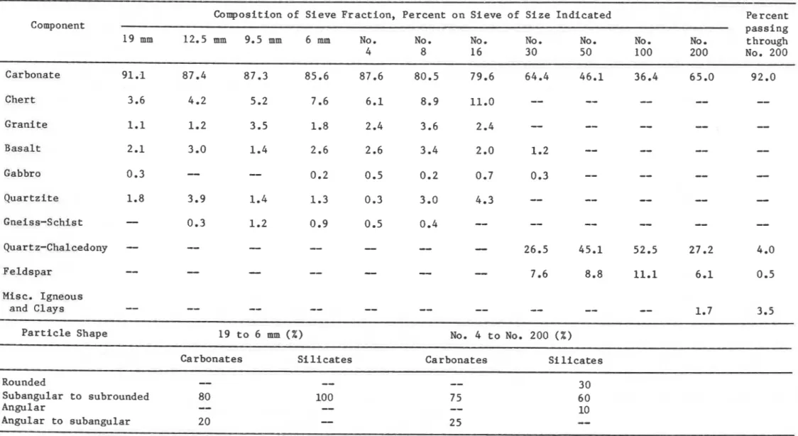
S i l i c e o u s s a n d and g r a v e l were from Eau C l a i r e , Wisconsin. The maximum s i z e of t h e a g g r e g a t e was 19 mrn (314 i n . ) . The p e t r o g r a p h i c i n f o r m a t i o n , g i v e n i n T a b l e s I1 and 111, was o b t a i n e d f o l l o w i n g t h e p r o c e d u r e s of ASTM C295-65
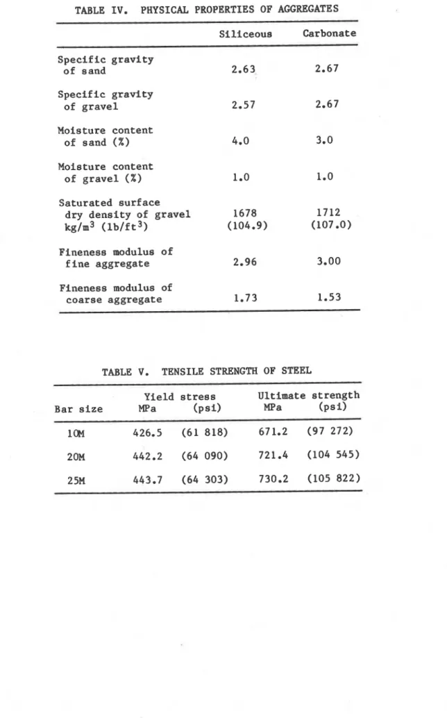
[ 3 ) . Sieve analyses were conducted. Gradation curves f o r t h e two aggregates a r e shown i n Figs. 1 and 2. Other i n £ ormation needed f o r proportioning t h e mix, such a s s p e c i f i c g r a v i t y , moisture c o n t e n t , u n i t weight, and f i n e n e s s modulus of t h e aggregates, i s l i s t e d i n Table IV.
S t e e l : Deformed bars meeting requirements of ASTM Designation:
A615-80 141 were used f o r main and t i e bars. The l o n g i t u d i n a l s t e e l b a r s i n t h e columns were 20M (No. 6 ) and 25M (No. 8 ) , and t h e t i e s were 10M (No. 3). A t e n s i l e t e s t was performed f o r each b a r s i z e t o determine y i e l d and
u l t i m a t e s t r e n g t h . The test r e s u l t s a r e l i s t e d i n Table V.
Concrete Mix: Several t r i a l mixes f o r determining optimum p r o p o r t i o n s
were made t o produce a 34.5 MPa (5000 p s i ) s t r e n g t h n o n - a i r e n t r a i n e d
concrete. A waterlcement r a t i o of 0.6 was used f o r t h e carbonate aggregate c o n c r e t e and 0.5 f o r t h e s i l i c e o u s a g g r e g a t e concrete. Batch q u a n t i t i e s and measured p r o p e r t i e s of f r e s h c o n c r e t e a r e given i n Table V I .
The average 28-day c o n c r e t e s t r e n g t h s were 33.8 MPa (4898 p s i ) f o r carbonate aggregate c o n c r e t e and 34.2 MPa (4958 p s i ) f o r s i l i c e o u s a g g r e g a t e concrete. The i n d i v i d u a l 28-day s t r e n g t h s of t h e c y l i n d e r s a r e given i n Table I.
Fabrication
The columns were c a s t i n s p e c i a l l y designed forms. The reinforcement cage was assembled by welding t h e l o n g i t u d i n a l b a r s t o a s t e e l end p l a t e . Chromel-alumel thermocouples were secured t o t h e r e i n f o r c i n g s t e e l a t
s p e c i f i e d l o c a t i o n s a f t e r t h e cage was properly p o s i t i o n e d i n t h e form. I n o r d e r t o avoid any p o s s i b l e d i s l o c a t i o n of t h e thermocouples during c a s t i n g , a c a r e f u l working p l a n was followed a s d e s c r i b e d below.
Reinforcing b a r s and steel p l a t e s
The column l e n g t h was 3810 mm (12 f t 6 in.) measured from end p l a t e t o end p l a t e . The l o n g i t u d i n a l r e i n f o r c i n g b a r s were c u t t o 3800 mm
(12 f t 5 112 in.). The b a r s were machined a t both ends, f o r a l e n g t h of 19
mm
(314 in.) f o r t h e 203 and 305 mm ( 8 and 12 in.) columns t o a diameter of 12.7 nun (112 i n . ) , and 19 mm, r e s p e c t i v e l y . The b a r s of t h e 406 mm(16 i n . ) column were machined f o r a l e n g t h of 31.8 mm ( 1 114 in.) t o a
diameter of 19 mm. Fig. 3 shows d e t a i l s of t h e f i n i s h e d bars. A micrometer was used t o measure t h e diameters of t h e machined segments.
The dimensions of t h e end p l a t e s were 863 x 863 x 38 mm
(34 x 34 x 1 112 in.) f o r t h e 406 mm (16 in.) s q u a r e column and
533 x 533 x 25 mm ( 2 1 x 21 x 1 in.) f o r t h e 203 and 305
mm
( 8 and 12 i n . ) square columns. Holes 20.6 mm (13/16 in.) i n diameter, spaced t oaccommodate t h e l o n g i t u d i n a l b a r s , were d r i l l e d through t h e p l a t e s .
The main b a r s and ties were t i e d t o g e t h e r t o complete t h e s t e e l cage. The cage t h e n was placed v e r t i c a l l y on a l e v e l l e d end p l a t e i n such a way
Welding
The p r o v i s i o n s of AWS Designation D12.1-75 [ S
]
were followed when welding p l a t e s and b a r s . These members were p r e h e a t e d w i t h a propane t o r c h t o 288OC (550°F), t o prevent b r i t t l e f a i l u r e d u r i n g welding. The s i d e f i l l e t weld was done around b a r s on t h e i n n e r f a c e of t h e bottom p l a t e . McKay E10018-D2 and DYTRON-579 welding rods were used. Both t y p e s of welding r o d s have t e n s i l e s t r e n g t h of 834.9 MPa (121 000 p s i ) . Mild-steel welding rods were used t o f i l l up t h e 6 mm (114 i n . ) deep h o l e s on t h e o u t e r f a c e s of t h e p l a t e . The rough s u r f a c e s of t h e welded j o i n t s on t h e o u t e r f a c e of t h e p l a t e were ground t o a smooth f i n i s h .The welding of t h e t o p steel p l a t e was performed a f t e r t h e c a s t i n g of t h e columns. Before p o s i t i o n i n g t h e t o p p l a t e a 6 mm (114 in.) l a y e r of mortar was spread over t h e t o p of t h e column t o e n s u r e good c o n t a c t between s t e e 1 p l a t e and concrete. The m o r t a r was made of 1 p a r t cement and 3 p a r t s s i l i c e o u s sand. Using t h e same procedure a s f o r t h e bottom p l a t e , t h e t o p p l a t e was welded on t h e o u t e r s i d e t o t h e b a r s and smoothed.
Forms
-
Forms were made f o r t h e 203 mm (8 i n . ) , 305 mm (12 in.) and 406 mm (16 in.) s q u a r e columns. A t t h e s t a r t of c a s t i n g t h e f r o n t s i d e of t h e form was l e f t open f o r d e p o s i t i n g f r e s h concrete. Plywood window p i e c e s were
b o l t e d t o t h e form t o c l o s e t h e opening a s c a s t i n g p r o g r e s s e d upwards. Thermocouples
Butt-welded chromel-alumel thermocouples w i t h a t h i c k n e s s of 0.912 mm (0.0359 i n . ) were used t o make thermocouple frames f o r measuring c o n c r e t e temperatures a t s e v e r a l l o c a t i o n s i n d i f f e r e n t c r o s s - s e c t i o n s of t h e columns. Each frame c o n s i s t e d of a number of thermocouples t i e d t o s t e e l rods t h a t were f i r m l y secured t o t h e main r e i n f o r c i n g bars. Temperatures were meas~lred a t o n e q u a r t e r h e i g h t , a t mid-height and a t t h r e e q u a r t e r h e i g h t of t h e column. A t mid-height t h e temperatures were measured a l o n g t h e whole l e n g t h of an a x i s and a d i a g o n a l of t h e s e c t i o n ; a t t h e o t h e r two l e v e l s t h e temperatures were measured only along h a l f of t h e a x i s and h a l f of t h e d i a g o n a l of t h e s e c t i o n . The l o c a t i o n s of t h e thermocouples i n t h e c o n c r e t e a r e shown i n Fig. 4.
I n a d d i t i o n , a number of thermocouples were mounted on t h e r e i n f o r c i n g s t e e l b a r s and t i e s . The l o c a t i o n s of t h e thermocouples on t h e s t e e l a r e shown i n Fig. 5 and i n more d e t a i l i n Figs. 6 ,
7
and 8.Concrete Placement
Concrete was mixed i n a 0.17 m 3 (6 f t 3, t i l t i n g drum mixer. Shovels and scoops were used t o d e p o s i t c o n c r e t e i n t h e form. A s m a l l i n t e r n a l v i b r a t o r was c a r e f u l l y a p p l i e d t o c o n s o l i d a t e t h e concrete. A s c a s t i n g progressed upward, t h e window p i e c e s were s u c c e s s i v e l y c l o s e d and t i g h t l y bolted t o t h e form t o avoid p o s s i b l e m o i s t u r e l e a k s . The t o p s u r f a c e of t h e column was s c r e e d e d and f i n i s h e d w i t h a s m a l l wood f l o a t .
L i f t i n g hooks were embedded on o p p o s i t e s i d e s of t h e specimen a t 800 mm ( 2 f t 7 1/2 i n . ) from t h e t o p of t h e column. A humidity w e l l was p o s i t i o n e d a t mid-point f o r measuring r e l a t i v e humidity a t mid-depth of t h e column. C u r i n g
Concrete was cured under damp b u r l a p f o r 7 days a t 21 t o 24OC (70 t o 75OF). Forms were t h e n s t r i p p e d , and columns c o n d i t i o n e d i n a n atmosphere c o n t r o l l e d a t 21 t o 24OC and 30 t o 40% r e l a t i v e humidity.
Four columns, t e s t e d a t a near-oven-dry c o n d i t i o n , were k i l n - d r i e d a t about 93OC (200°F) and 0 t o 5% r e l a t i v e humidity. They were removed from t h e k i l n p e r i o d i c a l l y t o c o o l a t 23OC (73OF) s o t h a t t h e r e l a t i v e humidity i n t h e c o n c r e t e could be measured. A f t e r t h e d e s i g n a t e d m o i s t u r e c o n d i t i o n was reached, t h e columns were wrapped i n p l a s t i c t o prevent change i n t h e i r m o i s t u r e c o n t e n t . I n c a l c u l a t i o n s , t h e m o i s t u r e c o n t e n t of t h o s e columns i n near-dry c o n d i t i o n was assumed t o be 0%. The moisture c o n t e n t of t h o s e columns i n e q u i l i b r i u m w i t h t h e atmospheric m o i s t u r e was assumed t o be 5% by volume.
LOAD
ANDFIRE EXPOSURE CONDITIOBS, I n determining t h e c o n d i t i o n s , such a s l o a d , i t s a p p l i c a t i o n , and f i r e i n t e n s i t y , under which t h e f i r e performance of columns a r e t o be s t u d i e d , s e v e r a l approaches can be followed. The f i r e performance can be examined f o r :
1) maximum l o a d i n g c o n d i t i o n s determined i n accordance w i t h
A C I 318-77 [ 6 ] o r CSA-CAN A23.3-M77 [ 7 ] ;
2) s t a n d a r d f i r e t e s t c o n d i t i o n s a c c o r d i n g t o ASTFE119 [ 8 ] o r ULC-S101 [ 9 ] ;
3) c o n d i t i o n s assumed
i n
t h e mathematical model f o r the c a l c u l a t i o n of f i r e r e s i s t a n c e of t h e columns;4 ) c o n d i t i o n s t h a t occur i n a c t u a l p r a c t i c e .
The f a c t o r s t h a t determined t h e d i f f e r e n t c o n d i t i o n s considered i n t h e f i r s t phase of t h i s s t u d y , a r e g i v e n i n Table V I I . They i n c l u d e t h e
assumptions w i t h regard t o load and i t s a p p l i c a t i o n , column l e n g t h and m a t e r i a l p r o p e r t i e s , and f i r e temperature.
I n t h e second column of t h e t a b l e t h e c o n d i t i o n s s p e c i f i e d i n ACI-318
[ 6 ] o r CSA-CAN A23.3 [ 7 ] a r e given. The c o n d i t i o n s t h a t occur i n a c t u a l
p r a c t i c e d u r i n g a f i r e (column 5) a r e assumed t o be e q u a l t o t h e s e c o n d i t i o n s , w i t h t h e exception of loads. Whereas a l l l o a d s (dead, l i v e , wind l o a d s , e t c . ) a r e t a k e n i n t o account i n conventional d e s i g n of
s t r u c t u r a l members, f o r a c t u a l f i r e c o n d i t i o n s , u s u a l l y only t h e dead and p a r t of t h e l i v e l o a d a r e p r e s e n t d u r i n g t h e f i r e .
All
o t h e r l o a d s , such a s wind o r earthquake, may be neglected. I n t h e t h i r d column t h e s t a n d a r d f i r e t e s t c o n d i t i o n s , according t o ASTM-El19 [ 8 ] o r ULC-S101 [91,
a r e given.These c o n d i t i o n s d i f f e r from t h o s e i n a c t u a l p r a c t i c e i n r e s p e c t t o l o a d a p p l i c a t i o n and f i r e temperature. I n t h e s t a n d a r d f i r e t e s t a c o n c e n t r i c
load i s a p p l i e d , whereas i n p r a c t i c e t h e r e i s always some e c c e n t r i c i t y o f Loading. A minimum i s s p e c i f i e d f o r s t r u c t u r a l d e s i g n i n ACT. o r CSA codes. The o t h e r d i E f e r e n c e i s t h a t i n t h e t e s t t h e f i r e temperature i n c r e a s e s continuously according t o a s t a n d a r d i z e d r e l a t i o n , whereas i n a c t u a l
p r a c t i c e i t can follow numerous c o u r s e s , i n c l u d i n g a p e r i o d of t e m p e r a t u r e r i s e and decay.
I n t h e f o u r t h column t h e c o n d i t i o n s assumed i n t h e mathematical model f o r c a l c u l a t i o n of t h e f i r e r e s i s t a n c e of t h e columns a r e shown. The c o n d i t i o n s were s e l e c t e d t o resemble a s c l o s e l y a s p o s s i b l e c o n d i t i o n s d u r i n g t h e f i r e t e s t , w i t h r e g a r d t o load, column end c o n d i t i o n s and
m a t e r i a l p r o p e r t i e s . I n t h e f i r s t phase of t h e s t u d y , o n l y exposure t o t h e s t a n d a r d f i r e , d e s c r i b e d i n ASWE1 19 [8] o r ULC-S101 [ 9 ] was considered.
CALCULATION PROCEDURE
The c a l c u l a t i o n of t h e f i r e performance of t h e columns i s c a r r i e d o u t i n v a r i o u s s t e p s . It i n v o l v e s t h e c a l c u l a t i o n of t h e t e m p e r a t u r e s i n t h e column, and i t s deformations and s t r e n g t h d u r i n g t h e exposure t o f i r e .
Temperatures of
Column
The column temperatures a r e c a l c u l a t e d by a f i n i t e d i f f e r e n c e method [ l o ] . This method has been p r e v i o u s l y a p p l i e d t o t h e c a l c u l a t i o n of
temperatures i n s q u a r e r e i n f o r c e d c o n c r e t e columns [ I ] . Because t h e method of d e r i v i n g t h e h e a t t r a n s f e r e q u a t i o n s and c a l c u l a t i n g t h e t e m p e r a t u r e s i s d e s c r i b e d i n d e t a i l i n t h o s e s t u d i e s , i t w i l l n o t be d i s c u s s e d here; only t h e e q u a t i o n s used f o r c a l c u l a t i o n of t h e column t e m p e r a t u r e s , and
i n f o r m a t i o n n o t d e a l t w i t h i n p r e v i o u s s t u d i e s , w i l l be given. D i v i s i o n of c r o s s - s e c t i o n i n t o elements
The c r o s s - s e c t i o n a l a r e a of t h e column i s subdivided i n t o a number of elements, a r r a n g e d i n a t r i a n g u l a r network (Fig. 9). The elements a r e s q u a r e i n s i d e t h e column and t r i a n g u l a r a t t h e s u r f a c e . For t h e i n s i d e elements, t h e temperature a t t h e c e n t r e i s t a k e n a s r e p r e s e n t a t i v e of t h e e n t i r e element. For t h e t r i a n g u l a r s u r f a c e elements, t h e r e p r e s e n t a t i v e p o i n t s a r e l o c a t e d on t h e c e n t r e of each hypotenuse.
Because only columns w i t h s q u a r e c r o s s - s e c t i o n s (and f o u r axes of symmetry) w i l l be considered, ir i s possible t o c a l c u l a t e t h e temperature d l s t r i h u r l o n t n only one-eighth of t h e c r o s s - e e c t l o n a l area of t h e column. A s i l l u s t r a t e d i n Fig. 9, i n an X-z c o o r d i n a t e system, a p o i n t P has t h e
coordfnares x = (m-1)
A E / ~
and z = ( ~ 1 )A F / ~ .
m,nEquations f a r t h e f i r e l c o n c r e t e boundary
It w i l l be assumed t h a t t h e columns a r e exposed on a l l s i d e s t o t h e h e a t of a f i r e whose t e m p e r a t u r e c o u r s e f o l l o w s t h a t of t h e s t a n d a r d f i r e d e s c r i b e d i n ASTM-El19 [ 8 ] o r ULC-S101 [9]. This temperature c o u r s e can be approximately d e s c r i b e d by t h e f o l l o w i n g expression:
j
where T i s t h e time i n hours and Tf i s t h e f i r e temperature i n O C a t t i m e T = A T . (A l i s t of nomenclature used i n equations i s given i n
Appendix A. )
The temperature rise i n each element can be derived by making a heat, balance f o r them. For a s u r f a c e element t h e temperature a t a time
T = ( j + l ) A ~ i s given by t h e expression:
J
Equations f o r i n s i d e t h e concrete
For t h e elements i n t h e concrete, t h e temperature
rise
a t t h e timeT = ( j + l ) A r i s given by:
<{rn+l ),(n+l) +
4,
2 Auxiliary equations
To c a l c u l a t e t h e temperatures of t h e elements along t h e l i n e s of
symmetry A-C and B-C, t h e temperature h a s t o s a t i s f y t h e following symmetry conditions:
l i n e A-C
l i n e B-C
I n order t o ensure t h a t any e r r o r e x i s t i n g i n t h e s o l u t i o n a t some t i m e l e v e l w i l l not be amplified i n subsequent c a l c u l a t i o n s , a s t a b i l i t y
c r i t e r i o n has t o be s a t i s f i e d which, f o r a s e l e c t e d v a l u e of
A t ,
l i m i t s t h emaximum of t h e time s t e p (AT). Following t h e method described i n r e f e r e n c e [ l l ] , i t can be derived t h a t f o r t h e fire-exposed column t h e c r i t e r i o n of s t a b i l i t y i s most r e s t r i c t i v e along t h e l i n e m+l, between f i r e and concrete. It i s given by t h e condition:
where t h e maximum value of t h e c o e f f i c i e n t of h e a t t r a n s f e r during exposure t o t h e s t a n d a r d f i r e (hmax) i s approximately 3 x l o 6 J / ~ ~ ~ O C
( 147 ~ t u / f t 2 h 0 ~ ) . E f f e c t of moisture
The e f f e c t of moisture i s taken i n t o account by assuming t h a t i n each element, t h e moisture s t a r t s t o evaporate when t h e temperature of t h e element reaches 100°C (212OF). During t h e period of evaporation a l l t h e h e a t supplied t o an element i s used f o r evaporation of t h e moisture, u n t i l t h e element i s dry. From a h e a t balance equation, t h e moisture
c o n c e n t r a t i o n i n an element a t t h e f i r e l c o n c r e t e boundary, a t t h e t i m e
T = ( j + l ) A r i s given by:
j j
+
2 i 3 ) 4 J .+
)I A S ~ E ~ E , [ ( T ~+
~ 7 3 ) ~-
(Tl,n (7 S i m i l a r l y , t h e moisture concentration i n an element i n s i d e t h e concrete a t , t h e time T = ( j + l ) A ~ i s given by:With t h e a i d of e q u a t i o n s ( 1 ) t o (8), and t h e r e l e v a n t m a t e r i a l p r o p e r t i e s given i n Appendix A, t h e temperature d i s t r i b u t i o n i n t h e column and on i t s s u r f a c e can be c a l c u l a t e d f o r any t i m e ( T = (j+l)Aer) i f t h e temperature d i s t r i b u t i o n a t t h e t i m e
AT
i s known. S t a r t i n g from a temperature of 20°C (68OF), t h e t e m p e r a t u r e h i s t o r y of t h e column can b e c a l c u l a t e d by r e p e a t e d a p p l i c a t i o n of e q u a t i o n s ( 1 ) t o (8).Calculation of Strength during Fire
Transformation i n t o s q u a r e network
To s i m p l i f y t h e c a l c u l a t i o n of t h e deformations and s t r e s s e s i n t h e column, t h e t r i a n g u l a r network i s transformed i n t o a s q u a r e network. I n Fig. 10 a q u a r t e r s e c t i o n of t h i s network, c o n s i s t i n g of s q u a r e elements arranged p a r a l l e l t o t h e
x-
and z-axis of t h e s e c t i o n , a r e shown. The w i d t h of each element of t h i s network i sAS/^.
The temperatures, deformations and s t r e s s e s of each element a r e r e p r e s e n t e d by t h o s e of t h e c e n t e r of t h e element. The temperature a t t h e c e n t e r of each element i s o b t a i n e d by a v e r a g i n g t h e t e m p e r a t u r e s of t h e elements i n t h e t r i a n g u l a r network according t o t h e r e l a t i o n :( j )
Tm,n s q u a r e 2 t r i a n g u l a r
where t h e s u b s c r i p t s 'square' and ' t r i a n g u l a r ' r e f e r t o t h e elements of t h e s q u a r e and t r i a n g u l a r network.
During exposure t o f i r e t h e s t r e n g t h of t h e column d e c r e a s e s w i t h t h e d u r a t i o n of exposure. The s t r e n g t h of t h e column can be c a l c u l a t e d by a method based on l o a d - d e f l e c t i o n a n a l y s i s which i n , t u r n i s based on a s t r e s s - s t r a i n a n a l y s i s of c r o s s - s e c t i o n s [ 2 ] . I n t h i s method, t h e columns, which a r e f i x e d a t t h e ends d u r i n g t h e tests, a r e i d e a l i z e d a s pin-ended columns of reduced l e n g t h KL (Fig. 11). The l o a d on t h e test columns i s i n t e n d e d t o be c o n c e n t r i c . To r e p r e s e n t i m p e r f e c t i o n s i n t h e columns, an i n i t i a l
The c u r v a t u r e of t h e column i s assumed t o v a r y from z e r o a t pin-end t o mid-height a c c o r d i n g t o a s t r a i g h t l i n e r e l a t i o n , a s i l l u s t r a t e d i n Fig. 11. For such a r e l a t i o n t h e d e f l e c t i o n a t mid-height ( y ) , i n terms of t h e
c u r v a t u r e ( X ) of t h e column a t t h i s h e i g h t , can be g i v e n by:
For any given c u r v a t u r e ( x ) , and t h u s f o r any g i v e n d e f l e c t i o n a t mid- h e i g h t , t h e a x i a l s t r a i n i s v a r i e d u n t i l t h e i n t e r n a l moment a t t h e
midsection i s i n e q u i l i b r i u m w i t h t h e a p p l i e d moment g i v e n by t h e product of l o a d and t o t a l d e f l e c t i o n . I n t h i s way a l o a d d e f l e c t i o n c u r v e c a n b e c a l c u l a t e d f o r s p e c i f i c times d u r i n g t h e exposure t o f i r e . From t h e s e curves t h e s t r e n g t h of t h e column ( i t s maximum l o a d c a r r y i n g c a p a c i t y ) can be determined f o r each t i m e . I n t h e c a l c u l a t i o n of column s t r e n g t h t h e f o l l o w i n g assumptions were made.
1) The p r o p e r t i e s of t h e c o n c r e t e and s t e e l a r e a s g i v e n i n Appendix A and l a t e r i n t h i s s e c t i o n .
2 ) The i n f l u e n c e of t h e presence of r e i n f o r c i n g s t e e l on t h e
temperature may be neglected. Thus t h e column, from a thermal p o i n t of view, may be t r e a t e d a s c o n s i s t i n g e n t i r e l y of c o n c r e t e . The temperature of t h e s t e e l i s assumed t o be e q u a l t o t h e temperature i n t h e column s e c t i o n a t t h e l o c a t i o n of t h e c e n t e r of t h e s t e e l . 3) Concrete has no t e n s i l e s t r e n g t h .
4 ) P l a n e s e c t i o n s remain plane.
5 ) I n i t i a l s t r a i n s i n t h e column b e f o r e t h e exposure t o f i r e c o n s i s t s of f r e e s h r i n k a g e of t h e c o n c r e t e and creep. Because mortar was i n s e r t e d a t t h e t o p t o make good c o n t a c t between t h e c o n c r e t e and t h e s t e e l end p l a t e , t h e i n i t i a l s h r i n k a g e w i l l be assumed t o be n e g l i g i b l e .
The t e s t s of t h e columns were s t a r t e d a f t e r a p r e l o a d i n g p e r i o d of about one hour. The s h o r t e n i n g of t h e column due t o c r e e p i n t h i s p e r i o d i s assumed t o be n e g l i g i b l e .
Based on t h e s e assumptions, t h e change of column s t r e n g t h d u r i n g t h e exposure t o f i r e was c a l c u l a t e d . I n t h e c a l c u l a t i o n s t h e s q u a r e network shown i n Fig. 10 was used. Because t h e s t r a i n s and stresses of t h e elements a r e n o t symmetrical w i t h r e s p e c t t o t h e x-axis, t h e c a l c u l a t i o n s of t h e s t r a i n s and s t r e s s e s were performed f o r both t h e network shown and an i d e n t i c a l network a t t h e l e f t of t h e x-axis. The f o r c e and moment i n t h e s e c t i o n were o b t a i n e d by adding t h e f o r c e s c a r r i e d by each element and t h e moments c o n t r i b u t e d by them.
The e q u a t i o n s used i n t h e c a l c u l a t i o n s of t h e s t r e n g t h of t h e column d u r i n g t h e exposure t o f i r e a r e g i v e n below.
Equations f o r t h e s t e e l
From t h e assumption t h a t p l a n e s e c t i o n s remain p l a n e , t h e s t r a i n i n t h e r e i n f o r c i n g s t e e l i s e q u a l t o t h e a x i a l s t r a i n of t h e column ( s) and t h e
s t r a i n due t o bending of t h e column (zs/p), where zs is t h e h o r i z o n t a l d i s t a n c e of t h e r e i n f o r c i n g s t e e l bar t o t h e v e r t i c a l plane through t h e x- a x i s of t h e s e c t i o n of t h e column, and p i s t h e r a d i u s of curvature. The s t r a i n causing stress, however, is determined a s t h e d i f f e r e n c e between t h i s s t r a i n and t h e f r e e s t r a i n
[ (
),] t h a t would t a k e p l a c e due t o thermal expansion of t h e steel. For t e steel a t t h e r i g h t of t h e x-axis, t h i s s t r a i n[ (
E ~ ) ~ ] i s given by:2
For t h e s t e e l elements a t t h e l e f t of t h e x-axis, t h e s t r a i n
[(
c ~ ) ~ ]i s
given by:
The s t r e s s e s i n t h e elements of t h e network a r e c a l c u l a t e d u s i n g stress- s t r a i n r e l a t i o n s d e r i v e d from d a t a provided by Ingberg and S a l e [12], and Witteveen, Twilt and Bylaard [13]. These r e l a t i o n s i n c l u d e t h e e f f e c t of creep a t e l e v a t e d temperatures and were obtained a t h e a t i n g r a t e s
approximately those t h a t occur i n a f i r e i n a c t u a l p r a c t i c e . The r e l a t i o n s have been g e n e r a l i z e d f o r o t h e r s t r u c t u r a l s t e e l s by assuming t h a t , f o r a given temperature, t h e curves a r e t h e same f o r a l l steels, but t h e stress below which t h e s t r e s s - s t r a i n r e l a t i o n i s l i n e a r , i s p r o p o r t i o n a l t o t h e y i e l d s t r e n g t h of t h e steel. This i s i l l u s t r a t e d i n Fig. 12, where t h e s t r e s s - s t r a i n curves a t 20°C (68OF) a r e shown f o r a steel w i t h a y i e l d s t r e n g t h of 250 MPa (36 p s i ) and f o r t h e r e i n f o r c i n g steel, which has a y i e l d s t r e n g t h of 443 MPa (64.3 p s i ) . I n Fig. 13 t h e s t r e s s - s t r a i n curves of t h e r e i n f o r c i n g steel a r e shown f o r v a r i o u s temperatures. These curves r e f l e c t t h a t even a t t h e very high temperature of 800°C (1472OF) t h e s t e e l s t i l l possesses some s t r e n g t h and r i g i d i t y . The equations t h a t d e s c r i b e t h e r e l a t i o n between t h e stress i n t h e s t e e l (f ), t h e s t r a i n ( c S ) and t h e
Y
temperature of t h e s t e e l (T) a r e a s follows. f o r
where
f o r
With t h e a i d of e q u a t i o n s (10)-(16) t h e stresses a t mid-height i n t h e s t e e l can be c a l c u l a t e d f o r any v a l u e of t h e a x i a l s t r a i n ( e ) , c u r v a t u r e ( l / p ) and t e m p e r a t u r e (T). From t h e s e s t r e s s e s t h e l o a d t h a t t h e s t e e l c a r r i e s and t h e c o n t r i b u t i o n of t h e s t e e l t o t h e moments can be d e r i v e d . Equations f o r t h e c o n c r e t e
I n t h e same way a s f o r steel, t h e s t r a i n i n t h e c o n c r e t e c a u s i n g s t r e s s f o r elements a t t h e r i g h t of t h e x-axis (Fig. 10) can b e g i v e n by:
and f o r elements a t t h e l e f t of t h e x-axis by:
where
( E ~ ) ~ = f r e e s t r a i n due t o thermal expansion of t h e c o n c r e t e ,
E = a x i a l s t r a i n of t h e column,
zc = h o r i z o n t a l d i s t a n c e of t h e c e n t e r of t h e element t o t h e v e r t i c a l p l a n e through t h e x-axis of t h e column s e c t i o n , p = r a d i u s of curvature.
The stresses i n t h e elements a r e c a l c u l a t e d u s i n g s t r e s s - s t r a i n r e l a t i o n s based on t h e work of R i t t e r [14] and Hognestad [15]. These r e l a t i o n s have been s l i g h t l y modified t o t a k e i n t o account t h e c r e e p of c o n c r e t e a t e l e v a t e d temperatures. The m o d i f i c a t i o n s a r e based on r e s u l t s of work by Schneider and Haksever [ 1 6 ] and c o n s i s t of a movement of t h e maxima i n t h e s t r e s s - s t r a i n curves t o h i g h e r s t r a i n s w i t h h i g h e r
temperatures. These c u r v e s a r e shown i n Fig. 14 f o r a c o n c r e t e w i t h a c y l i n d e r s t r e n g t h of 35 MPa ( 5 k s i ) . The e q u a t i o n s t h a t d e s c r i b e t h e s e curves a r e a s follows:
f o r where I n t h e s e e q u a t i o n s f c = compressive s t r e n g t h of c o n c r e t e a t temperature T, f k = c y l i n d e r s t r e n g t h of c o n c r e t e a t temperature T , f r o = c y l i n d e r s t r e n g t h of c o n c r e t e a t 20°C
(68"F),
'C = s t r a i n of t h e c o n c r e t e , c, , = s t r a i n corresponding t o maximum s t r e s s . With t h e a i d of e q u a t i o n s (17)-(23) t h e s t r e s s e s i n each of t h ec o n c r e t e elements a t midsection can be c a l c u l a t e d f o r any v a l u e of t h e a x i a l s t r a i n ( c ) and c u r v a t u r e ( 1 1 ~ ) . From t h e s e s t r e s s e s t h e l o a d t h a t t h e
c o n c r e t e c a r r i e s and t h e c o n t r i b u t i o n of t h e c o n c r e t e t o t h e moments can b e derived.
TEST
CONDITIONS
AMD PROCEDUREThe t e s t s were c a r r i e d out by exposing t h e columns t o h e a t i n a f u r n a c e s p e c i a l l y b u i l t f o r t h i s purpose. The h e a t i n p u t i n t o . t h e t e s t f u r n a c e was c o n t r o l l e d i n such a way t h a t t h e average temperature followed a s c l o s e l y a s p o s s i b l e t h e s t a n d a r d t e m p e r a t u r e l t i m e curve g i v e n by Eq. (1). The
i n s t r u m e n t a t i o n and c h a r a c t e r i s t i c s of t h e f u r n a c e a r e d e s c r i b e d i n d e t a i l i n r e f e r e n c e [17]. The columns were a t t a c h e d by b o l t i n g t h e end p l a t e s t o a l o a d i n g head a t t h e t o p and a h y d r a u l i c j a c k a t t h e bottom. For t h i s
purpose, e i g h t 19 mm (314 in.) b o l t s , spaced r e g u l a r l y around t h e column 63.5 m (2 112 i n . ) from t h e s i d e s were used
a t
each end.S e v e r a l of t h e columns were t e s t e d under a l o a d , which was c o n c e n t r i c . The l o a d s were a p p l i e d about one hour p r i o r t o t h e t e s t .
On t h e d a t e of t e s t i n g , t h e r e l a t i v e humidity i n t h e c e n t e r of t h e c o n c r e t e and t h e c y l i n d e r s t r e n g t h of t h e c o n c r e t e were measured. The measured v a l u e s a r e given i n Table I.
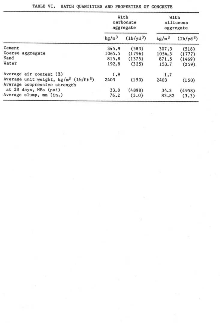
During t h e test, measurements were made of f u r n a c e temperatures a t e i g h t l o c a t i o n s w i t h t h e a i d of thermocouples. The j u n c t i o n of e a c h thermocouple was l o c a t e d 305 mm (1 f t ) from t h e t e s t specimen, a t v a r i o u s h e i g h t s . Two thermocouples a r e p l a c e d o p p o s i t e e a c h o t h e r e v e r y 610 mm
(2 f t ) along t h e h e i g h t of t h e f u r n a c e chamber. The l o c a t i o n of t h e i r
j u n c t i o n s and t h e i r numbering a r e shown i n Fig. 15. Thermocouples No. 4 and 6 were l o c a t e d a t a h e i g h t of 610 mm from t h e f l o o r , thermocouples No. 2 and 8 a t 1220 mm ( 4 f t ) , thermocouples No. 3 and 5 a t 1830 mm (6 f t ) and
thermocouples No. 1 and 7 a t 2440 mm ( 8 f t ) .
Measurements were a l s o made of t h e t e m p e r a t u r e s of t h e c o n c r e t e and s t e e l i n t h e column a t t h e l o c a t i o n s d e s c r i b e d e a r l i e r . The a x i a l s t r a i n of t h o s e columns t h a t were t e s t e d under a l o a d was a l s o measured. These
columns were c o n s i d e r e d t o have f a i l e d , and t h e t e s t was terminated, when t h e h y d r a u l i c j a c k , which has a maximum speed of 76 mm/min ( 3 in./min), could no l o n g e r m a i n t a i n t h e a p p l i e d load. Unloaded columns, which were
t e s t e d t o o b t a i n i n f o r m a t i o n on t h e temperature h i s t o r y i n t h e column, were exposed t o f i r e f o r 3 t o 5 hours, depending o n t h e i r s i z e . The d u r a t i o n of t h e v a r i o u s t e s t s , and t h e l o a d s t h a t were a p p l i e d , a r e g i v e n i n
T a b l e V I I I .
RESULTS*
AND DISCUSSION
Furnace TemperaturesThe f i r s t test was c a r r i e d o u t t o o b t a i n i n f o r m a t i o n on t h e c o n t r o l and u n i f o r m i t y of t e m p e r a t u r e s i n t h e f u r n a c e chamber. The t e m p e r a t u r e s i n t h e f u r n a c e measured d u r i n g t h i s test a t t h e v a r i o u s thermocouple l o c a t i o n s and t h e i r average, a s w e l l a s t h e s t a n d a r d f i r e temperatures according t o ASTM El19 [ 8 ] o r ULC SlOl [ 9 ] , a r e given a s a f u n c t i o n of t i m e i n Table IX. I n t h e p e r i o d of r a p i d t e m p e r a t u r e rise ( t o about t e n minutes) t h e r e a r e r e l a t i v e l y l a r g e d i f f e r e n c e s between t h e temperatures measured a t v a r i o u s h e i g h t s and between t h e average f u r n a c e t e m p e r a t u r e s and s t a n d a r d f i r e temperatures. A f t e r t h a t , t h e s e d i f f e r e n c e s become small and a high
temperature u n i f o r m i t y , a s w e l l a s average f u r n a c e temperatures t h a t follow c l o s e l y t h e s t a n d a r d f i r e temperatures, were obtained.
Because t h e p e r i o d of s u b s t a n t i a l temperature v a r i a b i l i t y i s s h o r t , t h e i n f l u e n c e of t h i s v a r i a b i l i t y o n t e m p e r a t u r e s i n t h e column i s n o t
s i g n i f i c a n t f o r f i r e exposure p e r i o d s of i n t e r e s t (about one hour o r more). The s m a l l i n f l u e n c e of t h e i n i t i a l v a r i a b i l i t y of f u r n a c e temperature c a n b e shown by comparing t h e temperatures measured a t v a r i o u s h e i g h t s a t s p e c i f i c d e p t h s i n t h e c o n c r e t e .
Temperatures i n Concrete
The temperatures measured i n t h e c o n c r e t e a t v a r i o u s h e i g h t s and d e p t h s a r e shown i n Fig. 16 f o r columns No. 1, 5 and 6 i n Table V I I I . For s p e c i f i c depths, t h e d i f f e r e n c e s i n temperature between t h e v a r i o u s h e i g h t s a r e small
a f t e r a n exposure time of about one hour. The s m a l l d i f f e r e n c e s i n d i c a t e * D e t a i l e d i n f o r m a t i o n on t e s t r e s u l t s i s a v a i l a b l e from t h e f i r s t author.
t h a t , f o r exposure p e r i o d s of one hour o r longer, t h e h e a t t r a n s f e r from t h e f u r n a c e t o t h e column may be regarded a s uniform.
I n Fig. 17 t h e average of t h e temperatures, measured i n t h e same columns a t o n e q u a r t e r h e i g h t , mid-height and t h r e e q u a r t e r h e i g h t , a r e shown f o r t h r e e depths i n each column. Also shown a r e c a l c u l a t e d
temperatures f o r t h e corresponding depths. The c a l c u l a t i o n s were c a r r i e d out f o r dry concrete. Although t h e test columns were i n near oven-dry c o n d i t i o n a t t h e t i m e of t e s t i n g , they s t i l l contained a s m a l l amount of moisture. There i s a r a p i d rise of t h e temperatures measured i n t h e deeper p a r t of t h e c o n c r e t e i n t h e e a r l i e r s t a g e s of t h e tests. T h i s r i s e may r e s u l t from thermally-induced migration of moisture towards t h e c e n t e r of t h e column. A t a l a t e r s t a g e , however, which i s t h e important s t a g e f o r p r e d i c t i n g t h e f i r e r e s i s t a n c e of t h e columns, t h e r e
i s
good agreement between measured and c a l c u l a t e d temperatures.Temperatures of
Steel
The temperatures measured on t h e main r e i n f o r c i n g s t e e l b a r s a r e shown i n Fig. 18 f o r columns No. 1, 5 and 6 i n Table V I I I . These measurements
were made i n column No. 6 w i t h thermocouples No. 3 and 9, l o c a t e d o p p o s i t e
each o t h e r w i t h r e s p e c t t o t h e c e n t e r of one b a r , and w i t h thermocouples No. 4 and 8, l o c a t e d o p p o s i t e each o t h e r on another bar (Fig. 6). The measurements i n column No. 1 were made w i t h thermocouples No. 3 and 9, l o c a t e d opposite each o t h e r on one b a r , and thermocouplee No. 4 and 1 0 , l o c a t e d i n s i m i l a r p o s i t i o n s on another b a r (Fig. 7). The measurements i n column No. 5 were made w i t h thermocouples No. 6 and 11 on one b a r and No. 4 and 12 on another b a r (Fig. 8). The curves i n Fig. 18 show t h a t t h e
d i f f e r e n c e s i n temperature between two o p p o s i t e p o i n t s of t h e b a r a r e r e l a t i v e l y small. Therefore, t h e average of t h e temperatures measured a t opposite l o c a t i o n s on a b a r is a good approximation of t h e average s t e e l temperature.
I n Fig. 19 t h e average s t e e l temperature
i s
compared w i t h temperatures c a l c u l a t e d a s d e s c r i b e d e a r l i e r i n t h i s paper. I n t h i s method, t h e column i s t r e a t e d a s c o n s i s t i n g e n t i r e l y of concrete, and t h e temperature a t t h e l o c a t i o n of t h e c e n t e r of t h e s t e e l i s chosen a s r e p r e s e n t a t i v e of t h e average temperature of t h e steel. Calculated steel temperatures a r e somewhat h i g h e r t h a n measured s t e e l temperatures. The d i f f e r e n c e s a r e small, however. Because a t high temperatures t h e s t e e l i s c o n t r i b u t i n g only a r e l a t i v e l y small p a r t t o t h e s t r e n g t h of t h e column, s m a l l d e v i a t i o n s i n s t e e l temperature have l i t t l e i n f l u e n c e on t h e column s t r e n g t h . The method i s t h e r e f o r e s u f f i c i e n t l y a c c u r a t e f o r c a l c u l a t i n g s t e e l temperatures. I n f l u e n c e ofLoad
To study t h e i n f l u e n c e of load on f i r e r e s i s t a n c e , f i v e i d e n t i c a l columns, made w i t h s i l i c e o u s aggregate, were t e s t e d under d i f f e r e n t loads. The columns t e s t e d , which had a s e c t i o n s i z e of 305 mm (12 in.) square, were
specimens No. 3, 4, 7, 8 and 9 i n Table V I I I . During t h e tests c o n c e n t r i c loads of 800, 711, 1067, 1778 and 1333 kN (180, 160, 240, 400 and 300 k i p s ) r e s p e c t i v e l y , were applied.
Calculations were a l s o made of t h e f i r e r e s i s t a n c e of t h e s e columns a s a f u n c t i o n of t h e load. It was assumed t h a t t h e moisture c o n t e n t i n t h e concrete was 5% by volume and t h e concrete s t r e n g t h was 35 MPa ( 5 k s i ) .
How t h e load a f f e c t s t h e f i r e r e s i s t a n c e of t h e columns i s shown i n Fig. 20, where measured and c a l c u l a t e d f i r e r e s i s t a n c e s f o r v a r i o u s l o a d s a r e given. Both measured and c a l c u l a t e d r e s u l t s show a s t r o n g i n f l u e n c e of t h e load on t h e f i r e r e s i s t a n c e of t h e columns. Calculated f i r e
r e s i s t a n c e s , however, a r e somewhat lower t h a n measured f i r e r e s i s t a n c e s . The d i f f e r e n c e s range from about 2 t o 16% of t h e measured f i r e r e s i s t a n c e s .
The maximum allowable load f o r t h e s e columns, f o r an e f f e c t i v e column l e n g t h of 3810 mm (12 f t 6 in.), i s about 900
IrN
(200 k i p s ) , according t o A C I 318 [ 6 ] o r CSA A23 [7]. For t h i s load, t h e f i r e r e s i s t a n c e of t h e column i s more t h a n 3 hours. A t p r e s e n t t h e National Building Code ofCanada [18] and A C I Guide 216 [19] a s s i g n a f i r e r e s i s t a n c e of about 2 hours t o t h i s column.
P a r t of t h e procedure of c a l c u l a t i o n of f i r e r e s i s t a n c e
i s
t h ec a l c u l a t i o n of t h e axial, deformation of t h e columns. T h i s deformation was a l s o measured during t h e t e s t s on loaded columns. Typical curves f o r
measured and c a l c u l a t e d a x i a l deformations a r e shown i n Figs. 21 and 22. In Fig. 21 t h e a x i a l deformation i s shown a s a f u n c t i o n of time f o r column No. 3 (Table V I I I ) , which was t e s t e d under a l ~ a d of 800 kN (180 k i p s ) and i n Fig. 22, f o r column No. 7, t e s t e d under a load of 1067
IrN
(240 k i p s ) . I n a l l c a s e s where t h e a x i a l deformation was measured, t h e r e was r e l a t i v e l y good agreement between t h e t h e o r e t i c a l and t h e experimentally derived curves. Near t h e f a i l u r e p o i n t , however, measured c o n t r a c t i o n s of t h e column a r e g r e a t e r than those c a l c u l a t e d . A p o s s i b l e reason f o r t h e d i f f e r e n c e i s t h a t t h e c o n c r e t e i s more d u c t i l e a t high temperature t h a n assumed i n t h e model. The i n f l u e n c e of t h i s d i f f e r e n c e on t h e f i r er e s i s t a n c e i s about t e n minutes. It i s s m a l l i n comparison w i t h t h e f i r e r e s i s t a n c e of t h e column, but can e v e n t u a l l y be taken i n t o account
empirically.
Influence
of Cross-Section
I n t h i s phase t h e i n f l u e n c e of cross-section was s t u d i e d mainly from a thermal p o i n t of view. A l l columns t e s t e d under a l o a d had a s e c t i o n s i z e of 305 x 305 mm (12 x 12 i n . ) , except one, which had a s e c t i o n s i z e of 203 x 203 mm ( 8 x 8 in.). A l l columns f a i l e d i n compression except t h e smaller one, which f a i l e d by buckling.
The i n f l u e n c e of s e c t i o n s i z e on t h e temperatures i n t h e concrete can be derived from t h e temperature curves given i n Fig. 17. For example, i t takes about 60 minutes t o reach a temperature of 300°C a t mid-depth i n t h e 203 x 203 mm column s e c t i o n , 90 minutes i n t h e 305 K 305 mm s e c t i o n and ' 180 min i n t h e 406 x 406 mrn s e c t i o n . The i n f l u e n c e of s e c t i o n s i z e on f i r e r e s i s t a n c e , f o r a s p e c i f i c load, w i l l be even g r e a t e r t h a n t h e i n f l u e n c e on temperature because, i n a d d i t i o n t o t h e slower temperature r i s e , t h e l a r g e r column a l s o has more a r e a of low temperature t h a t can c o n t r i b u t e t o c a r r y i n g t h e load.
I n f l u e n c e of Moisture
The i n f l u e n c e of moisture on f i r e r e s i s t a n c e was s t u d i e d t h e o r e t i c a l l y a s w e l l a s experimentally. For t h i s purpose a column (No. 2, Table VIII) was t e s t e d i n a n e a r l y dry state under a load e q u a l t o t h a t on a s i m i l a r , but normally-conditioned, t e s t column (No. 9). C a l c u l a t i o n s were a l s o made of t h e temperatures i n t h e column during f i r e exposure and of i t s f i r e r e s i s t a n c e a s 'a f u n c t i o n of load.
I n Fig. 23 measured temperatures, and i n Fig. 24 c a l c u l a t e d
temperatures, a t v a r i o u s d e p t h s i n t h e column, a r e g i v e n a s a f u n c t i o n of t i m e . The maximum d e l a y i n temperature rise, a t 180 minutes, due t o
moisture, i s about 20 minutes according t o t h e measurements and about 15
minutes according t o t h e c a l c u l a t i o n s .
The i n f l u e n c e of moisture on t h e f i r e r e s i s t a n c e of t h e column i s shown i n Fig. 25. I n t h i s f i g u r e , c a l c u l a t e d f i r e r e s i s t a n c e s a r e g i v e n a s a f u n c t i o n of load f o r a d r y column and f o r a column w i t h a moisture c o n t e n t of 5% by volume, r e p r e s e n t i n g a normal m o i s t u r e condition. For a l o a d of 1333 kN (300 k i p s ) , t h e load on t h e columns during t h e tests, t h e c a l c u l a t e d i n f l u e n c e of moisture on f i r e r e s i s t a n c e i s about t e n minutes. Somewhat higher f i r e r e s i s t a n c e s were obtained i n t h e tests than t h o s e c a l c u l a t e d . Also a somewhat h i g h e r i n f l u e n c e of moisture on f i r e r e s i s t a n c e (17 minutes) was found.
The r e s u l t s of tests and c a l c u l a t i o n s i n d i c a t e t h a t f o r normal f l u c t u a t i o n s i n t h e m o i s t u r e c o n d i t i o n of t h e c o n c r e t e ( f o r example, a moisture content of 3 t o 5%), moisture has only a small e f f e c t on t h e f i r e r e s i s t a n c e of t h e column.
I n f l u e n c e of Aggregate
Three columns made with carbonate aggregate were t e s t e d under d i f f e r e n t l o a d s (columns No. 10, 11 and 12 i n Table VIII). A comparison w i t h t h e f i r e r e s i s t a n c e of s i m i l a r columns, made w i t h s i l i c e o u s aggregate and t e s t e d under t h e same l o a d s , showed t h a t t h e f i r e r e s i s t a n c e of t h e carbonate aggregate columns was much higher than t h a t of t h e s i l i c e o u s aggregate columns. Under approximately t h e maximm allowable load, t h e f i r e . . r e s i s t a n c e of t h e carbonate aggregate column (No. 11) was almost twice a s high a s t h a t of t h e s i l i c e o u s aggregate column (No. 7). The d i f f e r e n c e was p a r t l y caused by a slower temperature rise i n t h e carbonate aggregate
column, p a r t i c u l a r l y a t h i g h e r temperatures (Fig. 26). A s u b s t a n t i a l p a r t of t h e d i f f e r e n c e was due t o t h e high d u c t i l i t y of t h e carbonate aggregate c o n c r e t e , which e n a b l e s t h e column t o undergo l a r g e a x i a l deformations without f a i l u r e (Fig. 27).
No c a l c u l a t i o n s were made of t h e f i r e r e s i s t a n c e of t h e carbonate aggregate columns because t h e m a t e r i a l p r o p e r t i e s of t h e c o n c r e t e of which t h e columns w e r e made, were not s u f f i c i e n t l y known. F u r t h e r s t u d i e s are
needed t o determine t h e thermal and mechanical p r o p e r t i e s of t h i s c o n c r e t e a t e l e v a t e d temperatures.
Of the variables studied in the first phase of the study program, load,
cross-section size and type of aggregate have the largest in£
luence on the
fire resistance of reinforced concrete columns. Particularly the use of
carbonate aggregate instead of siliceous aggregate will substantially
increase the fire resistance of the column. The influence of concrete
moisture content on fire resistance is, in the practical range,
insignificant.
The fire resistances of the columns studied are considerably higher
than those assigned to them in the National Building Code and in the
American Concrete Institute Guide 216.
Column temperatures, deformations and fire resistances calculated using
the mathematical model described in the present paper are in good agreement
with those measured.
The experimental results provide basic data on the fire resistance of
columns under standard fire test conditions. They also enable the
evaluation of assumptions used for calculating fire resistance by methods
based on heat transfer and structural analyses.
To develop general methods for the determination of the fire resistance
of concrete columns and walls for
a
wide range of applications, a second
phase of studies is planned. In this phase the effect of the following on
fire resistance will be studied:
1) restraint of column expansion,
2) strength of concrete,
3) use of lightweight aggregate,
4)
amount of steel,
References
1.
Lie, T.T. and Allen, D.E. (1972).
Calculations of the Fire Resistance
of Reinforced Concrete Columns, National Research Council of Canada,
Division of Building Research, NRCC 12797, Ottawa.
2. Allen, D.E. and Lie, T.T. (1974).
Further Studies of the Fire
Resistance of Reinforced Concrete Columns, National Research Council of
Canada, Division of Building Research, NRCC 14047, Ottawa.
3. Standard Practice for Petrographic Examination of Aggregates for
Concrete, (1979).
ASTI4 C295-79, American Society for Testing and
Materials, Philadelphia.
4.
Standard Specification for Deformed and Plain Bullet-Steel Bars for
Concrete Reinforcement, (1980).
ASTM A615-80, American Society for
Testing and Materials, Philadelphia.
5. Reinforcing Steel Welding Code, (1975).
AWS-Dl2 .l-75, American Welding
Society, Manlius, N.Y.
6. Building Code Requirements for Reinforced Concrete, (1977
).ACI
Standard 318-77, American Concrete Institute, Detroit.
7. Code for the Design of Concrete Structures for Buildings, (1977).
CAN3-A23.3-M77, Canadian Standards Association, Rexdale, Ontario.
8. Standard Methods of Fire Tests of Building Construction and Materials,
(1979).
ANSIIASTM El 19-79, American Society for Testing and
Materials, Philadelphia.
9.
Standard Methods of Fire Endurance Tests of Building Construction and
Materials, (1980).
ULC-S101+f1980, Underwriters' Laboratories of
Canada, Scarborough, Ontario.
10. Lie, T.T. and Harmathy, T.Z. (1972).
A
Numerical Procedure to
Calculate the Temperature of Protected Steel Columns Exposed to Fire,
Fire Study No. 28, Division of Building Research, National Research
Council of Canada, NRCC 12535, Ottawa.
11. Dusinberre, G.M. (1961).
Heat Transfer Calculations by Finite
Differences, International Textbook Company, Scranton, Pa.
12. Ingberg, S.H. and Sale, P.D. (1926).
Compressive Strength and
Deformation of Structural Steel and Cast-Iron Shapes at Temperatures up
to 950°C (1742OF).
Proceedings of the American Society for Testing and
Materials, Vol. 26, 11, Philadelphia.
13. Witteveen,
J., Twilt, L. and Bylaard, F.S.K.
(1977).
The Stability of
Braced and Unbraced Frames at Elevated Temperatures, Second Int.
14. Ritter, W. (1899).
Die Bauweise Hennebique, Schweizerische Bauzeitung,
Vol. 33, February.
15. Hognestad, E. (1951).
A Study of Combined Bending and Axial Load in
Reinforced Concrete Members, University of Illinois Engineering
Experiment Station Bulletin No. 399, Urbana.
16. Schneider, U. and Haksever, A. (1976).
Bestimmung der aquivalenten
Branddauer von statisch bestimmt gelagerten Stahlbetonbalken bei
naturlichen Branden, Bericht des Institute fur Baustoffkunde und
Stahlbetonbau der Technischen Universitat Braunschweig.
17. Lie, T.T. (1980).
New Facility to Determine Fire Resistance of
Columns, Canadian Journal of Civil Engineering, Vol. 7, NO. 3.
18. The Supplement to the National Building Code of Canada, (1980).
Associate Committee on the National Building Code, National Research
Council of Canada, NRCC No. 17724, Ottawa.
19. Guide for Determining the Fire Endurance of Concrete Elements, (1981).
Concrete International, Report No. ACI 216R-81, Detroit.
20.
Harmathy, T.Z. and Allen, L.W. (1973).
Thermal Properties of Selected
Masonry Unit Concretes, Journal of the American Concrete Institute,
Vol. 70.
TABLE I. DETAILS CONCERNING 1ST PHASE COLUMN TEST SPECIMeNS ( c r o s s s e c t i o n s 305 x 305 mm (12 x 12 in.) u n l e s s o t h e r w i s e noted) Compressive s t r e n g t h of Moisture c y l i n d e r s c o n d i t i o n of specimen a t
Specimen Cast Tee t t e s t d a t e a t 28 days a t t e s t d a t e C no. d a t e d a t e (%
RH)
MPa ( p s i ) MPa ( p s i ) S i l i c e o u s aggregate 1 77-6 7 9-95
34.2 (4953) not measured -2 7 -19 Carbonate aggregate 12 7 7-8 82-1 7 6 34.2 (4960) 38.5 (5580) -30 -22 41.4 (5996) across s e c t i o n 406 x 406 mm (16 x 16 i n . ) bcross s e c t i o n 203 x 203 nan (8 x 8 in.)TABLE 11. PETROGRAPHY OF SAND AND GRAVEL USED AS SILICEOUS AGGREGATE
Composition of S i e v e F r a c t i o n , P e r c e n t o n S i e v e of S i z e I n d i c a t e d P e r c e n t
Component Passing
19 mm 12.5 mm 9.5 mm 6 mm No. No. No. No. No. No. No. through
4 8 16 3 0 5 0 100 200 No. 200 I G r a n i t e Q u a r t z i t e Quart 2 c h e r t a Sandstone-Quartz Conglomerate Rhyolite-Dacite F e l d s p a r Diorite ~ r a y w a c l c e ~ Gneiss-Schist B a s a l t
Mf
s
c. Igneous Rocks and Opaque MineralsP a r t i c l e Shape 19 t o 6 mm (%) No.
4
t o No. 16 ( % ) No. 30 t o No. 200 ( X )Subrounded t o rounded 30 2 0 10
Subrounded t o subangular 40
40
40Angular 3 0 4 0 5 0
a " ~ r o n s t o n e , " made up of j a s p e r and h e m a t i t e , i s i n c l u d e d i n t h e c h e r t c l a s s i f i c a t i o n . ' ~ n c l u d e s metagraywacke.
he
miscellaneous igneous r o c k s were s e v e r e l y a l t e r e d and p o s i t i v e i d e n t i f i c a t i o n was impossible. The opaque m i n e r a l s o c c u r r e d i n t h e No. 50 and s m a l l e r s i e v e s i z e s and were l a r g e l y magnetite.TABLE 111. PETROGRAPHY OF SAND AND GRAVEL USED AS CARBONATE AGGREGATE
Composition of S i e v e F r a c t i o n , P e r c e n t o n S i e v e of S i z e I n d i c a t e d Pe r c e n t
Component p a s s i n g
19 mm 12.5mm 9.5mm 6mm No. No. No. No. No. No. No through
4 8 16 30 50 100 200 No. 200 Carbonate C h e r t G r a n i t e B a s a l t Gabbro Q u a r t z i t e Gneiss-Schist Quartz-Chalcedony F e l d s p a r Misc. Igneous and Clays
P a r t i c l e Shape 19 t o 6 mm ( % ) No. 4 t o No. 200 ( % )
Carbonates S i l i c a t e s Carbonates S i l i c a t e s Rounded
--
--
--
30 Subangular t o subrounded 80 10 0--
7 5--
60 Angular--
10 Angular t o subangular 2 0--
2 5--
TABLE I V . PHYSICAL PROPERTIES OF AGGREGATES S i l i c e o u s Carbonate - -- S p e c i f i c g r a v i t y of sand S p e c i f i c g r a v i t y of g r a v e l Moisture c o n t e n t of sand (%) Moisture c o n t e n t of g r a v e l ( % ) S a t u r a t e d s u r f a c e d r y d e n s i t y of g r a v e l kg/m3 ( l b / f t 3 ) Fineness modulus of f i n e a g g r e g a t e Fineness modulus of c o a r s e a g g r e g a t e
TABLE
V.
TENSILE STRENGTH OF STEELYield stress Ultimate s t r e n g t h
TABLE
VI.
BATCH QUANTITIES AND PROPERTIES OF CONCRETE With With carbonate s i l i c e o u s aggregate aggregate Cement Coarse aggregate Sand Water Average a i r content (%) Average u n i t weight, kg/m3 ( l b / f t 3, Average compressive strengtha t 28 days, MPa ( p s i ) Average slump, mm ( i n . )