Publisher’s version / Version de l'éditeur:
Vous avez des questions? Nous pouvons vous aider. Pour communiquer directement avec un auteur, consultez la
première page de la revue dans laquelle son article a été publié afin de trouver ses coordonnées. Si vous n’arrivez pas à les repérer, communiquez avec nous à [email protected].
Questions? Contact the NRC Publications Archive team at
[email protected]. If you wish to email the authors directly, please see the first page of the publication for their contact information.
https://publications-cnrc.canada.ca/fra/droits
L’accès à ce site Web et l’utilisation de son contenu sont assujettis aux conditions présentées dans le site LISEZ CES CONDITIONS ATTENTIVEMENT AVANT D’UTILISER CE SITE WEB.
Technical Memorandum (National Research Council of Canada. Associate Committee on Soil and Snow Mechanics), 1956-02-22
READ THESE TERMS AND CONDITIONS CAREFULLY BEFORE USING THIS WEBSITE. https://nrc-publications.canada.ca/eng/copyright
NRC Publications Archive Record / Notice des Archives des publications du CNRC :
https://nrc-publications.canada.ca/eng/view/object/?id=fe23da54-a119-4e8a-9abd-b252e3714a29 https://publications-cnrc.canada.ca/fra/voir/objet/?id=fe23da54-a119-4e8a-9abd-b252e3714a29
NRC Publications Archive
Archives des publications du CNRC
For the publisher’s version, please access the DOI link below./ Pour consulter la version de l’éditeur, utilisez le lien DOI ci-dessous.
https://doi.org/10.4224/40001148
Access and use of this website and the material on it are subject to the Terms and Conditions set forth at
Proceedings of the Eastern Muskeg Research Meeting
The Associate Committee on Soil and Snow Mechanics is
one of about thirty 3pecial committees which assist the National Research CO\mcU in its work. Formed in 1945 to deal with an urgent wartime probll!tlll involVing soil and
snow, the COIII'II1ttee i. nov pertorming its intended task ot
co-ordinating Canadian research studies concerned with the physical and mechanical properties ot the terrain ot the Dolll1niOll. It does this through subcOllllll1ttees on Snow and
Ice, Soil Mechanics, Muskeg, and Fermatrost. The Com-mittee, which consists ot about fitteen Canadians ap-pointed as individuals and not as representativell, each tor a 3-78ar term, has funds available to it tor making
research grant. tor work in its fields of interest.
In-quiries will be welcomed and should be addrened to: The
Secretar,y, Associate Committee on S01l and Snow"Mechanics, c/o The Division ot Building Research, National Research Council, ottawa, Canada.
This publication is one of a series being produced by the Associate COIIIIl1ttea on Soil &rid Snow Mechanics of the National Research Council. It may theretore be reproduced, without amendment, provided that the Division is told in advance and that full and due aclmo\"lledgment of this publication is always made. No abridgment or this report may be published without the written authority ot the Secretary of the A.C.S.S.M. Extracts may be published for purposes of review only.
-.-. ----.
__
. セ .- - - _
. . .⦅ M M M M M M M セNATIONAL RESEARCH COUNCIL
CANADA
ASSOCIATE COMMITTEE ON SOIL AND SNOW MECHANICS
PROCEEDINGS
OF THE
EASTERN MUSKEG RESEARCH MEETING
FEBRUARY
22, 1956
Technical Memorandum No.
42
Ottawa
October
1956
I II
1
FOREWORD
This is the record of the Second Annual Muskeg
Research Meeting which was held in the PavilIon Mgr
Vachon of Laval University in Quebec City, Quebec, on
February 22nd,
1956.
A list of those in attendance is
included as Appendix A of these proceedings.
The
meeting was the first to be held in Eastern Canada and
was sponsored by the Associate Committee on Soil and
Snow Mechanics of the National Research Council.
The conference took the form of two technical
sessions.
The morning session was under the
Chairman-ship of Mr. J.O. Martineau.
Four papers were presented
and discussed and a progress report given on the work
of the newly-formed Special Committee on Muskeg of the
Canadian Petroleum Association.
The afternoon session
was chaired by Mr. W.C. Harrison and Mr. B.C. Nowlan.
Three papers were presented and discussed.
Progress
reports were given of muskeg research now under way at
McMaster University and the National Research Council.
The sessions were ended by a discussion on various
topics of interest regarding organic terrain.
Morning Session of February 22
Section 1
Section
2.Section
3
TABLE OF CONTENTS
Introductory notes
Techniques of road construction over
organic terrain by I.C. MacFarlane
Measurement of the shearing strength
of muskeg by Dean R.M. Hardy and
S. Thomson
Page
12
16
(ii)
25
Section
4
Section
5
The application of aerial survey over
organic terrain by Dr. N.W. Radforth
Economic aspects of muskeg with respect 31
to oil production by R.A. Hemstock
Section
6
Report of the special committee on
muskeg or the Canadian Petroleum
Association by J.P. Walsh
41
Arternoon Session of February 22
Section
7
Section
8
Section
9
Section 10
Section 11
Appendix A
Muskeg as it affects the economics of
45
the forestry industry in Quebec by
Dr
0A. Lafond
The need for rehabilitation of organic
46
terrain in Ontario wit h special
reference to reforestation by R.N.
Johnston and Dr. G.A. Hills
Problems in muskeg accessibility by
55
J.R. Russ
Progress reports
A-Muskeg research at the National
58
Research Council by I.C. MacFarlane
B-Muskeg research at McMaster
62
University by Dr. N.W. Radforth
General discussion
63
List of those present at the Eastern
Morning Session, February 22
Section 1
INTRODUCTORY NOTES
The Chairman, Mr. Martineau, introduced Dean A. Pouliot
of the Faculty of Science of Laval University, who welcomed
those present to the PavilIon
vセイVachon and Laval University.
He said that Laval University was anxious to co-operate with
the National Research Council and other Canadian universities,
and to participate in the blending of the two cultures,
-especially in the field of science.
He also paid tribute to
Dr. Radforth, Chairman of the Muskeg Subcommittee, for his work.
The Chairman then introduced Dr. N.W. Radforth who spoke
briefly in French.
He then explained that muskeg was truly a
national problem, and expressed the hope that the Quebec meeting
would be profitable and inspire mutual co-operation to overcome
many of the muskeg problems.
Dr. Radforth next introduced the three Chairmen for the
technical sessions, pointing out that as Mr. Martineau was one
of the original members of the Muskeg Subcommittee, he was
a
most appropriate and capable Chairman.
Mr. Martineau also is
believed to be the first engineer in the country to present a
paper (at the Western Muskeg Research Meeting,
1955)
concerning
road construction over organic terrain in Quebec.
Dr. Radforth
went on to say that Mr. Harrison also was known to many because
of his presentation at the Edmonton meeting of a paper which
outlined the muskeg problems of the forestry people.
In his
introduction of Mr. Nowlan, Dr. Radforth said that as Head of
the Special Contracts Department of the Bell Telephone Company,
Mr. Nowlan had encountered special and unique problems with
muskeg.
2 Section 2
TECHNIQUES OF ROAD CONSTRUCTION OVER ORGANIC TERRAIN by
Ivan C. MacFarlane I. INTRODUCTION
This is a review of the methods used by various countries and organizations in overcoming the peculiar problems of building roads across what is ambiguously termed muskeg, peat bog, meadow bog, swamp, marsh, fen, heath, barren, moor - to mention a few of the more polite terms.
Definition
For engineering purposes "muskeg" (or "organic terrain" as it has now become known) may be roughly defined as "that
terrain which is made u of a livin or anic mat of mosses,
sed es and or rasses with or without tree rowth underlain b
an extremely compressible mixture of partly disintegrated and
decomposed organic material.II It is characterized by low bearing
capacity and abnormally high water content. The depth of such a
deposit of vegetable matter (or "peaty material") may vary from
a few inches to many feet. The mineral soil substratum is
usually a clay, silt, or a silty clay, but in some instances is a sand or gravel.
The word "road" is used here in the popular sense of the
term, meaning "any track that is used for travel, conveying goodsj
etc. " It applies equally well to the bush road as to a part of
the Trans-Canada highway system. The Problem
Considering the definition of organic terrain (muskeg) and knowing its nature, it is apparent that this terrain is
highly unpredictable and generally cannot be expected to furnish
a very firm or dependable base for a road. Muskeg is normally
unstable under application of load so that normal means of road construction (e.g., earth or rock fill dumped on the ground
surface and spread evenly) are usually inadequate for organic
terrain areas.
In general, there are two エセセ・ウ of failure of roads built
over organic terrain:
(1) failure by lateral flow (or shear); and
Lateral flow failure is the more likely type in very
wet muskego
The gravitational force of the fill placed on
the surface of the organic deposit
セtransmitted laterally
through the subsurface (organic) material, thereby "squeezing"
this material out from beneath the fillb
The fill is caused
to subside and he av I ng of the surface to the sides of the
embankment frequently re?ultso
This effect is sketched in
Fig.
10In drier muskeg areas, failure may be caused by the
fill, because of
ゥエセweight, penetrating into the
ュオウォ・ァセthereby causing subsidence of the embankment as a result of
the consolidation of the organic material and sometimes of
the substratum as well o
'.
The choice of e particular method of construction
will depend a great deal on local conditions, so that
ponstruc-tion should always be preceded by an accurate survey of the
area.
The depth of the organic deposit should be carefully
determined, and a profile of the contours of the substratum
should also be plotted.
This cannot be over-emphasized as a
means of ach
Levi.ng a design for the proposed road that will
reduce the possibility of later difficulties.
There are three main ways to construct a road over
organic terrain:
(1)
Floating the road on the muskeg;
(2)
Removing the unstable material and replacing it with fill; or
(3)
Supporting the road on piles (a method rarely, if ever,
used in Canada).
A possible fourth method 1s stabilization of the
muskeg by mechanical or chemical means , but this is really' a
subsidiary to (1).
IL
FLOATING THE ROAD ON THE MUSKEG
Frequently the liVing organic mat is of such a depth
and strength that it provides sufficient stability to support
a certain height of fillo
The fill may then be floated on
the muskego
This method is generally the cheapest in initial
cost and is especi-a1ly suitable for very deep muskeg deposits
where methods involving removal of the unstable subsurface
material are' not economically feasible
0Severe differential
set tlements often occur however, the settlements extending
over a number of years, so that the road has a bad riding
surface and is expensive to maintain.
Spread Foundation
The fill can be placed directly on the organic mat in
a spread type of foundationo
This is designed with a very
wide base ana flat side slopes' so that the hL:hway loads c an
be carried over a wide area. Since this type of construction
is dependent upon the stability of the surface mat by virtue of its "basket" or "membrane" effects> care should be taken to
assure that the mat is not broken by the fill material. For
this reason, the fill should be sand or gravel rather than rock.
Clay is not recommended since it inhibits drainage. The
spread type of foundation was used extensively in the bUilding of the first roads in the Highlands of Scotland.
Corduroy or Fascine Constrgction
If it is thought that the surface mat has insufficient strength, an alternative method to the spread type of
founda-tion is corduroy or fascine construcfounda-tion. This consist& of
a mat of logs (either placed ウゥ、・セ「ケMウゥ、・ or 」イゥウウM。イッウウセ or
planks and brushwood, which float the embankment ウッセ・エィゥョァ like
a pontoon bridgeo The purpose of such a method of construction
is:
(1)
(2 )
( 3)
To provide a certain amount of buoyancy for ウオセーッイエゥョァ
the road;
To spread the キ・ゥセィエ of the road as evenly セウ ーッセウゥ「ャ・
over the muskeg and thus rRduce differential setttementj and
To prevent the fill material from penetrating the surface of the muskeg and sinking into ito
Considerable labour is involved in making and laying corduroys so the method is costlYll and its use for major roads
is decreasingo Normallyj) it is used only on minor roads, but
this method of construction was often used on the Alcan
High-way where muskeg was encountered. In the pastj) it has been
used quite extensively in Europej) the United States and Canadao
other Materials
Materials other than logs and brushwood have been used
to increase the buoyancy of the surface mat of the muskego In
the UoSoAoj) wire mesh has been used occasionally for this
purpose o Dried bundles of peat have been used as a base for
the fill in s」セセ、ゥョ。カゥ。 and Hollandj) and in Great Britain
bundles of straw have been used o Lateral Support
When roads that must sustain セ・。カケ traffic loads are
floated on muskegy it may be necessary to provide lateral
support to prevent failure of the subsurface materialo This
can be accomplished by building 」ッオョエ・イキ・ゥセィエ fi11s on either
side of the roadway to stabilize the unstable organic mater-I a l
beneath the main embankment 0 An al te rnati ve method セ used in
S
on either side of the roadway embankment and filling it with rocko
1110 EXCAVATION AND REPIA CENiENT BY STABLE FILL MATERIAL
Total Excavation and Backf:ll
The most obvious approach to the whole problem of
con-struction over organic terrain is to excavate the unstable material
and to backfill with mineral soilo 1his method is considered by
many engineers to be the only really dependable way of building a
permanent road over muskego Howe ver-, it can be economically
fea si bLe only for shallcw de pt.h.s 0 Opinion differs a s to what the
maximum economic depth should beg it varies from
6
to 12 feet inthe United sエ。エ・Sセ
18
feet is recommended in g・イュ。ョケセ and 12 feetin Hollando Excavation may be carried out most efficiently by
mechanical means (dragll:r.e) but lt is difficult because the trench
fills with water and the sides slough ino Another method of
excavation is to use explosives in the so=called "Trench Method of
Blasting"o This usually entails blasting a trench (or ditch) about
SO
feet in length and immediately lackfilling it with stablematerialo Trench blasting is recommended when the muskeg is quite
firm and will not slip9 and whBre the organic material is not more
than 12 to
IS
feet d66puPartial Excavntion and Backfill
In this method only part of the unstable material is
excavatedo The amount removed may vary from a removal of the
sur-face mat to a fairly deep exoavationo Such a procedure is sometimes
followed in fairly shallow deposits where the type of construction
doe s not warrant the cost of a complete e xc av at Lon , The same methods
for removing the organlc materibl may be used as in total excavationo
Regardless of the method of &xcavationj the fill material
should be a porous soil such as sand or gravel to provide adequate
drainage 0 Clay fill is not r-e c onme nde d , Since the fill does not
settle to the bottom of the cr-gani c de p o sLt. , the road is aotually
floating in ito The embankment 1S supported by the side and upward
pre ssure of the sur-r-ound i ng peaty rna t.er-La L 0 The f ill will continue
to sink until pressure is セアオ。ャゥコ・、 and a certain degree of sta=
bility is reachedo
IVo displaceセヲヲゥnt METHODS
gイ。カゥエlMdゥウーャ。」・ュ・ョセ
When an earth fill is placed on the surface of an
organic depositp it will ineVitably settle until either
6
This may take yearso The natural period of settlement due to
gravity may be accelerated in a number of different ways, all of which involve displacing the unstable organic material
from beneath the embankment after it has been placedo A
ウオイ」ィ。イセ of
IS
to 20 feet in excess of the fill may be usedセ。」」・ャ・イ。エ・ settlement0 The excess is later removed when the
f1ll has settled adequatelyo If the peaty material is too
stiff to be easily displaced by the weight of the embankment
and a surcharge 。ャッョ・セ it can be softened by impregnating it
with water, a process known as "jettingtto After an embankment
has been built across a muskeg area, water jets are directed
through the fill into the organic material belowa These jets
are sunk rapidly to the bottom of the organic deposit, then
slowly withdrawno The increase in water content considerably
reduces the stability of the organic material so that the embankment displaces it and the fill settles to the bottomo This method is considered by some American experts to be
especially suitable for displacement of deep deposits of fairly soft organic materiala
The Michigan State Highway Department uses a water jet method extensively, but the principle is different from that
outlined aboveo The embankment is constructed across the
ュオセォ・ァL and about 10 feet of surcharge addedo This fill is then saturated to a near "quick" condition by proper
arrange-ments of the water jet s , The increased weight of bhe
embank-ment due to the water displaces the peat and causes the fill
to settle0 The surcharge is then removed and the fi11. brought
to gradeo Bog Blasting
The use of explosives is a means of displacing the organic rna terial from beneath t he embankment where other
methods are unsuitableo There are two main variants to the
blasting method: underfill blasting, and the toe shooting
mebhod ,
(1) Underfill Blastinga - Before the embankment is placed,
it is usual to break up the surface mat by light chargeso
This promotes an even settlement of the fillo After the
reqUired quantity of the granUlar fill material ィ。セ been
placed on the surface of the muskeg, explosives are placed benea th t he embankment a t or near the bottom of the organic
deposito This may be accomplished by water jets or by the use
of casings, driven down through the fill and the organic
materiala The amount of explosives used and the number of
holes will depend upon the depth of tQe muskeg and the height
bf
fillo The usual procedure is to ィ。セ・ one or more rows ofcharges along the centre-line of the embankment and a further row or rows of subsidiary charges just outside both sides of
the filloo To permit a more effective displacement, the outside
charges are detonated a moment before the main centre chargeso The force of the explosives is confined from above by the
7
fill and from below by the hard bottomp so it follows the path
of least resistance = to the sideso The blast displaces the
organic material under the fill to one sidsp liquefies the
surrounding mater-La L, and creates a cavity beneath the
embank-ment, allowing it to settle rapidly to solid bottomo
This method of displacement is said to be effective for
depths of unstable material up to 30 feet o It has been used
successfully in the United States (especially Michigan)v Eirep
and Ger-many ,
Figure 2 1s a series of diagralnmatic sketches to illustrate the underfill blasting methodo
The Refier Method of Blasting is a combination of the
under-fill and trench systems of accelerated settlemento The fill is
placed on the surface of the muskeg (the surface mat being broken
up as before)o Ditches are then dug on both sides of the fill
either by mechanical means or the trench blasting methodo These
side ditches relieve the lateral pressure 80 that the weight of the
fill can more easily push out the underlying soft material to the
sideso Settlement can be allowed to take place naturally or may be
accelerated by detonation of light charges under the fill and beneath the ditches to aid in liquefaction of the organic material o
(2) The Toe Shooting Method of Blastingo セ In this methodp the
unstable material ahead of the advancing fill is blasted o More fill
is then dumped into the cavity left by the blast and is advanced
with a "Vn point until it forces the peat up in a wave ahead of ito
A surcharge of fill is added and charges are placed around the toe
of the fillo These are detonated and the organic material is blown
out ahead of the fillo The fill Is built up again and the process
repea.ted o This method is used for soft peats up to a depth cf 20
feeto Figure
3
illustrates the toe shooting methodoFor deeper deposits (up to about
50
feet) a similarprocedure is followed" known as torpEldo blast.ingo Instead of エィセ
whole charge being at the bottom
of
the ッイァ。ョi」セ、・ーッウゥ t , sticks ofexrlosives are tied at various points on a long pole about 10 feet
in lengtho Several of these "torpedoes" are placed upright in the
unheaved peat at the end of the fill.> and are then de t.ona t.e d , The
results are similar to the toe shooting methodo
Vo PILE CONSTRUCTION
Pile founda tions br-ansmtt the weight of the road directly to
the firm stratum underlying the muskego By this method all settle=
ment is eliminated and there is a minimum of disturbance of the peat
during constructiono Its use has been limited ohiefly to roads in
8
This method is very expensive and its use has been restricted fairly well to eオイッー・セ particularly HoL'Larid , although the method has been used in the United States o One case is recorded of creosoted timber piles being driven through the organic material and then capped 「セ longitudinal reinforced concrete beams carrying the pavement sLab ,
VIo
STABILIZATION OF
MUSKEG Surface dイ。ゥョ。セDrainage of a muskeg area is usually extremely difficult and often impossibleo Much of the literature on this important aspect of organic terrain concerns the drainage of bogs for recla= mation of the peat as a fuelo Road engineers can learn much about drainage methods from the peat industry and agriculturalists o How= everg even when circumstances are such that some drainage can be
carried out, usually only the surface can be drainedo Because of the way in which the water is retained,(l the water content of the peat is affected for only a very short distance away from the drain-age dLt.che s ,
A number of factors contribute to the difficulty of draining an organic deposit by normal methods of drainage such
as
ditching and well-pointso Frequently the deposit is in a low-lying area and there is no outlet for the drainage ditcheso The most important factor of all to consider,(l ィッキ・カ・イセ is the nature of the material itselfo Of particular relevance to the problem of drainage is themanner in which the peat holds watero Even when there is an out-let for the ditches» drainage can at best remove but a fraction of the water in the organic material o
There are various 0ombinations of water in ー・。エセ a brief review of these will illustrate the difficulties involved in
trying to drain this materialo water is held in five combinationsg
(I}
Water of occlusicn (water present in the larger cavitIe S
1n the peat, as in a sponge0 Can bepartially removed by drainage9 especially if there
is a load on the muskeg to squeeze out the water)9 (2) Capillarr wetel' (watar pre sent in the fibre sand
tissues that make up the organic material,(l as in a blotter)E
Colloidally bound water c e
rIU"1os e
gelsTr==--=="-=-=(4)
セセAセ\_⦅。ANセゥl
「ッセセ。エセエY
9
(5)
cセ・ュャ」。ャAi b2uEd セセセ。イ (water of hydration) aIn drainage te o hr.Lque s all but (1) and (2) are of academic
interest onlyo The problem is to remove the water held by those
two combinations o
Attempts are frequently made to drain an area of organic
terrain prior to 」ッョXエイオッエャッョセ especially when the flotation method
is contempla"Cedo There are two schools of thought on the mattero
One reoommends that the area be drained 8S well as possible before
con at r-uot j on , but once the embankment (or other form of road
construction) has been floated on the muskeg no further attempts
at drainage should be madey except to remove excessive surface
water due to r-a Lnf'a LL, The other point of view advocates no dr-a i
n-age at 。ャャセ except to drain excessive Burface watero
The first opinion seems to be the more prevalent at the
present timeo In Great Britain and Canada i t is fairly common
practice to dig quite deep ditches beside roads which 。セ・ floated
on organic terraino Although the upper layers of the organic
material are drained t.her-eby and the shear strength is increased
(and therefore the stab iIi ty) i' thez-e are certa in disadvantage So
The drainage is an extremely slow procedure and involves considerable volume shrinkage of the peat and subsequent settlement of the roado
Alsop by dLgg Lng a ditch ad je c ent to the rvoad , much of the lateral
support of the peat is イ・ュッカ・、セ increasing the d8nger of fallureo
A
compromise solution is the uXセ of double drainageo A ditch about50
feet to either side of the road is used to drain the excessivesurface watero The ditches adjacent to the roadway then have a
fairly constant depth of water which minimizes alternate swelling and ahr-Lnkage of the pe-a t under- 7.,he road0
Sand Drains
The sand drain method of s t.abi Lt z atn on was developed
specifically to accelerate se t t.Lerne nt and イセGセイャNウッャゥ、。エZゥッョ of marshy
areas and has been used e xt.en sj ve Ly for sntiy 8c1130 Its use has
many advocates in the constructIon of roads over certain types
of organic terralno The pr-Lnc i.p Le is very s i mpLe , The time
required for consolidation of a aol1 varies 83 the square of the
length of the e sc ape pa th of th e soil moisturea The pur-p o se of
vertical sand drains is to reduc6 the distance the water has to
travel by permittlng it to travel horizontally BS well as
ve r t Lo aL'Ly , thus shortening the period of oons o Lf dat t on ,
Vertic.al holes are dug into t he soft f'oundatt on and
are backfilled with B clean sando To allow a horizontal flow
of water as well as a vertical ヲャッキセ a セ。ョ、 blanket» 2 to
8
, i)
embankment is then built on top of this sand blanketo The
weight of the fill squeezes the water from the organic
material and into the vertical sand 」ッャオュョウセ where it rises,
エィ・ッイ・エゥ」。ャャケセ to the level of the ウセャョ、 blanket and drains
awayo The sand columns also serve to Lnc r-eas e the stability
of the organic material in the initial stages of consolidation, preventing it from failing in lateral shear due to the weicht of the embankm0,nt"
The snnd drain method has beenlsed chiefly in the U.S.A. but has also been used to a limited extent in Burope and South America"
Chemical Stabilization
Considerable success has been achieved in stabilizing mineral soils by using various types of stabilizers such as
cements9 resins9 chemical ィ。イ、・ョゥョァセ bitumens9 and freezingo
It is undertermined whether such methods would be of value in stabilizing organic soils as these soils are chiefly vegetable in character and likely would not respond to the above-noted
treatments as do mineral soilso Although from time to time
one hears of a ahemical ormher means of muskeg stabilization, to date there does not appear to be any adequate solution to this problem"
VIIo CONCLUSION
This brief paper has attempted to present a resume of the current methods of constructing roads across organic
terrain, Only the more important ーッゥョセ of each method have
been described" Perhaps nothtng ョセキ has been presented for
those who are thoroughly familiar with all aspects of highway
construction9 but it is hoped セィ。エ it has been informative
to those who have not been too closely associated with this aspect of organic terrain exploitation"
BIBLIO:1RAPHY
A Preliminary Annotated Bibliography on Muskeg compiled by
IoCoMacFarlane, Bibliography Noo ャャセ Division of BuiJrling
Research, National Research Council, Ottawao September
19550
Sections "F" and "G""
Field Manual of Soil Engineering (Third Edition)" Michigan
State Highway Dept"9 Lansing9 Michigano August
19540
Chapter
4"
Soil Mechanics for Road EngLne er-s , Her Najesty's Stationery
Office9 London9
1952"
Chapter250
.ioad Crosses Swamp on Timber Pile Foundatt on , En;rineering and
SUMHARY
ROAD CONSTRUCTION OVER ORGANIC TERRAIN
セ
I
I
Relocation Construction in Muskeg Unavoidable Pile Construction Excavation of Muskeg and Replacement I I i Total Partial Excavation Excavation Displacement Methods1
I
iGravity Displo Bog Blasting
Surcharge
I
Ttlater Jetting
undJrfill Toe
ウセッッエゥョァ
Blasting Method
Relief Hethod Torpedo Blasting
I - I I
Lateral Muskeg Stabilization
Support
L--,
n。エセイ。ャ
SJnd ChemicalDrainage Drains Stabilization Road on Muskeg
1,_
_-Floating
spJead cor!uroy
oエセ・イ
Foundation Construction Materials Peat Straw Vlire me sh
DISCUSSION
Mr. Merrill asked if the piles mentioned in the paper were bearing piles, i.e., did they go down to the
mineral layer. He wondered if friction piles could not
be used. Mr. MacFarlane replied that the piles referred
to were bearing piles extending to mineral soil. He
thought that in very deep, somewhat stable muskeg, some sort of friction pile might work, but he had never heard of it.
Mr. Maduke inquired about the spacing of the
explosives in the underfill method of blasting. Mr.
MacFarlane said that he did not have the figures available
but that they are in the literature. Spacing of explosive
charges will depend upon such factors as depth of fill, type of muskeg, etc.
Dr. Radforth remarked that he had heard of one
instance where piles were used under culverts, anticipatory
to settlement. In this case, the road settled but the
culverts did not, resulting in a'most undesirable condition.
He pointed out that this ゥャャオウセ・、 the need of gathering
information about particular conditions prior to construction. It is also necossary to think of new methods of construction. Dr. rセ、ヲッイエィ said that it was for this reason that he
appreciated the comprehensive discussion by Mr. MacFarlane on techniques already in use.
FILL
,
. / - '/ . \ - " ' - / • J セN . / (. 'セ
ORGANIC '-.,.---セ
'L" " . .Zセ
セN
ORGANIC",;' " )-セ MATERIAL')<
X
セ MATERIAL セ r ""r-
セセ
/
j \セ
. ./ , , " ,/,
",-
--'
/ } ("
.'
" - - セ H セ. ... . . J , , " ,セ / _ _.", セ """-'\ . )(.-
" '
...
-
"...-
--
..,.,.
-
...-- --
_...
-
セ ."'
. '" 7??Y????W??W??W?W?";;';»;.j:: »; .; ., »; »; ;., .; .; ., .;7?? ?? '7????
? 'l 'l?
'l;
MINERAL SOIL BASE
FIGURE 1
EFFECT OF FILL ON ORGANIC MATERIAL
( LATERAL FLOW FA I LURE)
'::.'. :.. (B)
セN t
t
t.
セ
.: .. '
F ILL . ..r
1
i '.
セN
. / . ;::. .' . ' . セMN l , セ ) PEAT ..;::<:': .. .. ::.,
PEA T セ⦅." -.
\,
.r:
.(."'-' f ,)." .' " ?"oX
"
JJ.L!/ . \
. セvityI·'....:. . \.
cセyZZ] / "ho/?
_______Y_______Gャ_セ_
. .:..'-.-,:-:'.セ. : :<" F I L L · '-.. 1 PEAT '. '.- PEAT ' \ .,' . .' .•••.• ' •. ' . ' : •.•• : : : . ' , ' I ' • 'c, .:.... .. " " " . " " , " ( , , : " ( '\.. I " . , . I . . ' MAIN CHARGES"' ; '\W_[_[セ_____セ____GGャB____
SUBSIDIARY CHARGES (A) . . ' . '.' PEAT \ . F ILL. . ... ' セ .:. . . ' ' . .. f 'r:
r--t
\ '-J " : " . . . .,
セNG J,
- -
-
- -
-
-
-
-
-,
I \ I .... '. ',' . ..,'
. . FILL.' ..••.. PEAT .,... . ' ... f, ( l'
': ,.:
: ..: ;: ..:.:...
1'; '..
セ : : ( . ; ) ., CAY I T Y . '-セN
f
7?????????ijo/???????????ij?
(C) (D)FIGURE
2
OPERATION
OF
UNDERFILL BLASTING METHOD
FAI?I.ANE.-PEAT .v.. ':.:':. '.::.:'::.:' . , , . ' FILL J. . , . . "
"-.. ' ", . '" -, PEAT . " \ . / ' . I ""- CHARGE '\. ,- . FILL . . . .:':,':.':"'.,:.:..,-, (A) ( B)FIGURE
3
TOE SHOOTING METHOD OF BLASTING
16
Section 3
Measurement of the Shearing Strength of Muskeg by
Dean R.M. Hardy and S. Thomson
Numerical values for the strength of muskeg are pertinent to problems concerned with road construction over muskeg and
traffic ability of muskeg under 10 adings I'r-orn vehicles moving
over it. To those who have had experience with construction in
muskeg areas, the effect of overloading the muskeg by the weight
of a road embankment is well known. The embankment sinks down,
the muskeg at the toes of the embankment is pushed up, and
some-times a series of mud waves form on either side of the
embank-ment. Once such movements have occurred, the embankment
continues to sink gradually until the muskeg material is
completely displaced below it and the embankment is resting on
a harder material below the muskeg. Under these circumstances
the settlements which occur may amount to several feet.
Experience has also shoHn that with muskeg soils it is frequently possible to move a single vehicle across a muskeg area, but, if traffic is continued for even a few passes of
wheel loads, subsoil failure quickly develops. There are, of
course, circumstances where the surface of muskeg, for all practical purposes, is completely incapable of carrying any
appreciable axle loadings.
These problems involve a break-down of the muskeg
material under loading in a manner similar to that which occurs
in any other type of soil. It is standard engineering practice,
when dealing with soil problems, to determine the soil character-istics such as shearing strength and compressibility and then, in terms of these values, to assess the effects that certain loadings will produce on the soil.
In theory, there is no reason why the same procedure
should not be followed with muskeg. In practice, however, there
are certain difficulties which, up to now, have made it impossible
to do so. The most important strength characteristic of a soil,
in relation to the type of problem we are concerned with, is
its shearing strength. Conventionally, shearing strengths can
be determined by securing so-called undisturbed samples in the field and running shearing strength tests on these samples in a
laboratory. In most cases, this procedure is not practically
possible with muskeg soils because the characteristics of the
material are such that it is impossible to ウセューャ・ it satisfactorily
A second very satisfactory method of assessing the shearing strength of a natural soil is to use a stability analysis in an area where a sliding failure has occurred. A simple survey of the over-all dimensions of an area where a slide has occurred, along with the knowledge of the original topography, will permit a computation to be made for the
average shearing strength of the soil involved. Actually,
this method can give an average value for shearing strength that is usually more accurate than any ever achieved by laboratory tests on small representative samples from the
area. The method has obvious limitations, however, because
suitable slide areas may not be available for analysis in the chosen area, and it is impractical to wait until an
embankment failure occurs to assess the shearing strength of the material.
The procedure of analysing failure conditions to arrive at a shearing strength of muskeg has been used in a limited
number of cases wit h muskeg soils. In fact, the most reliable
values available at the present time for the shearing strength
of muskeg have been determined from stabiLtty analyses made where a road embankment has overloaded the muskeg and a failure has occurred.
A third method for assessing the shearing strength characteristics of soils, which has received a considerable
amount of attention in the field of soil mech anics in the
past few years, involves the measurement of the shearing
strength in situ. Penetration tests come within this category.
The most recent instrument to be developed for this purpose,
however, is the so-called vane tester. Its main advantages,
in comparison to other in situ tests, are that it is
comparat-ively simple to use, and stresses produced in the soil by the instrument are subject to more accurate mathematical analysis than, for example, is the case Nith penetration tests.
If rational analyses are ever to be made of a wide variety of engineering problems concerned with muskeg, it is essential that information be acquired on the numerical range of values for shearing strength in muskeg or, alternatively, that practical methods for measuring its shearing strength be developed.
The junior author of this paper undertook, under the direction of the senior author, as an M.Sc. thesis project, to investigate the possibilities of adapting the vane tester to
measure the shearing strength of muskeg. To be of practical
18
value the equipment must be portable, ioe0 9 able to be carried
on foot by not more than two men9 and it should be such that
the field tests can be conducted by two operators if necessary. With these points in mind, modifications were attempted on a
more-or-less standard type of vane tester to meet the portability requirements and also to adjust the measuring portion of the
instrument to secure a reasonable degree of accuracy within the range of strengths likely to be encountered in muskeg soils (1).
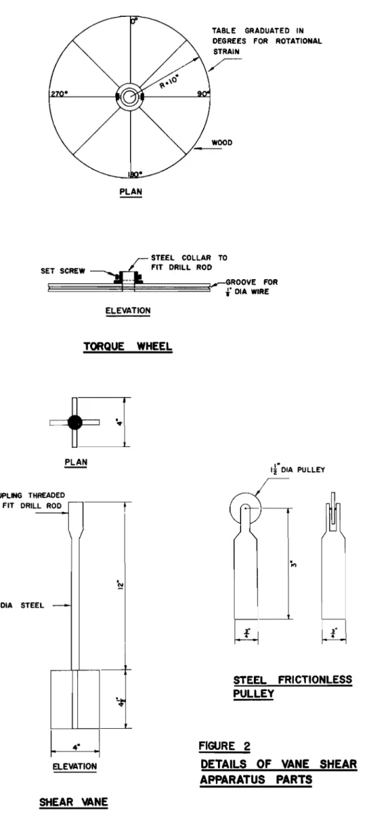
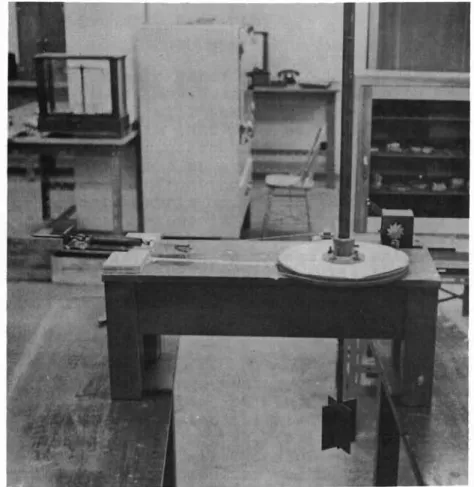
The details of the equipment, as finally modified, are
shown on Figures 1 and 2. Figure 3 is a general view of the
equipment set up in the laboratory.
Subsequent modifications have substituted torque wrenches for the calibrated spring to measure the shearing
resistance of the soilo In fact 9 following initial field
tr.'.c:.ls with the equipment shown in Figure 1, a number of
modifications were made. The original equipment functioned
satisfactorily, however9 and an interesting set of shearing
strength determinations were determined in the field at a location on the Northwest Highway System.
The field tests were made close セッ mile
253
on theAlaska Highway of the Northwest Highway System. The water table
in the area of the tests was at the surface. The area could be
traversed on foot without much difficulty but it was inaccessible
to conventional-type vehicles. The thickness of muskeg varied
from a deRth of 12 feet to 17 feet below the surface. It was
underlain by a soft? blue clay. The surface of the muskeg was
living vegetation but the degree of decomposition of the organic
material increased with depth. At all depths it was distinctly
fibrous in nature.
A typical set of shearing strength determinations on
one of the test holes is shown in Table 10
In ァ・ョ・イ。ャセ the test results showed that the shearing
strength increased directly with the depth. It is notable,
however, that in all cases the maximum shearing strength was only developed after an extraordinarily high degree of
deformationo Thus, while the shearing strength at the greater
depths was surprisingly high, it could only be developed after very substantial deformations had occurred in the soil.
19
Laboratory tests on samples of the muskeg showed the specific gravity of the sOlI solids to be in the nature of
1.4. Natural moisture contents were measured within the
range of 470-760 per cent) based on the dry weight of the soil particles.
One of the unresolved questions in connection with these initial field measurements is the extent to which the fibrous nature of the soil may increase the measured shearing
strength using the vane tester0 In comparing the measured
shearing strengths wi th the rather scant results available for shearing strengths of muskeg based on computations in
areas where failure has occurred under embankment 10adingsJ
the field tests show somewhat higher strength at depth than would be expected from the available results of stability
analyses. On the other hand limited unconfined compression
tests run on undisturbed samples of the higher strength
material encountered in these test holes, gave shearing strengths
ranging from 150 Ibo per sqo ft. to as much as 430 lb. per sq.
ft., with a fairly good correlation with the results from the vane test at the same depth,
The shearing strengths from the vane tests at shallow depths are in fairly close agreement with the available data
from stability analyses. One would expect to get a considerable
variation in relationship between strength and depth for different
locations. The investigation has shown that it is feasible to
measure shearing strengths with the vane tester, but additional work is required to establish the accuracy of the test and
evaluate factors such as the fibrous nature of the material. The equipment was developed in the Civil Engineering
Department of the University of Alberta and the field tests
were run with the co-operation of the Northwest Highway System,
wィゥエ・ィッイウ・セ Yukon. REFERENCE
1. Lea, N.D. and B.D. Benedict; The foundation vane tester
for measuring ゥョセウゥエオ shear strength of soil. From the
Proceedings of the Sixth Canadian Soil Mechanics Conference,
ACSSM. Tech. Memo, 270 National Research Council, Ottawa,
20
TABLE I
TEST DATA FROTc1 STATION !J.20 + 00
Depth below surface Feet 1.75 3.25
4.75
6.25 7 ..55 9.05 10.55 12.05 Shear Deformation Strength at max.stress Ib/ft Degrees 106 55 204 40 160 85 300 100 415 55 487 45 555 25 610 20 Start clay 12.55 1020 10 1460 45 DISCUSSIONMr. Perry asked if there was any correlation with time
in the results from the vane エ・ウエセ as he thought the time factor
would be very important, Dean Hardy replied that, as the time
factor was indeed an important one, they standardized their
rate of torque of 6@per minute 9 which is a rather slow application
of load. A faster load application would give higher shearing
strengths. He said that they do have graphs of stress vs.
deformation but there are no figures to compare the results of
a fast test vs. a slow test, Dean Hardy admitted that the high
results were unexpected and may be characteristic of the
parti-cul.ar- locality0 The results will be checked eventually by test
21
Mr. Townsend referred to a paper by Ward concerning the settlement of a filIon a thin peat layer (Ward, W.H.,
A. Perrm an , and R ..F. Gibson, "Stability of a Bank on a Thin
Peat Layer," gセッエ・」ィョゥアオ・Nカ
5:
2:154-163, 1955).
Thecon-clusions were that the slip was due to increased pore pressures
in the peat layer. Mr. Townsend said that while in England
he had been associated wi th the c onstr-uc t.Lon of a fill in fen
country. The embankment had failed when the soil analysis
predicted that it would not. The conclusion was that failure
was due to a too rapid rate of placement of the fill. When
the remainder was placed more slowlyv no more difficulty was
experienced. Mr. Townsend asked what was the extent of mineral
soil in the muskeg. with regard to the correlation of strength of muskeg with depth.
Dean Hardy replied that identification made by eye only
showed very little evidence of much mineral soil; it was highly
organic soil. With regard to the slow application of load, Dean
Hardy said that the rate application of fill deals with the
process of consolidationo In the application of the vane tester,
one is not dealing with consolidation. The rate of loading
affects the fibres in the ュオウォ・ァセ not the pore pressure. In the
top part of deposit there is a "sponge effect" but lower down there is more decomposition and the consolidation process comes into effect.
When Mr. Maduke asked what sort of laboratory tests were run and for what purpose} Dean Hardy replied that not many
laboratory tests were carried out. They were in the nature of
an afterthought. A number of deep samples were taken (where the
strength is higher) and were sent to the laboratory in Shelby
tubing. Unconfined compression tests were carried out on the
samples. Dean Hardy said that this could not be done on
samples from higher up in the deposit as the muskeg was too fibrous.
22
TORQUE WHEEL
HAND WINCH
NOTE e= 81
fDIA AIRPLANE CABLE
SPRING 8 ULLEY D---'...---t---t---PULLEYS POINTER (MOUNTED ON TABLE)
I
r
DIA DRILL ROD1'- 8"
.1
CALIBRATED SPRING \ 2 r . r CHANNEL IRON OCKSCREW TORQUE WHEEL MイMセMLMMMMMMMMKMMM[MMMMMMMMQ f - - - , - _ '0 .I WOOD TABLEL
W
SHEAR VANE FIGURE IVANE SHEAR APPARATUS
(ASSEMBLY DRAWING)
23
TABLE GRADUATED IN DEGREES FOR ROTATIONAL STRAIN
PLAN
セ STEEL COLLAR TO
SET SCREW FIT DRILL ROD
: -- :_GROOVE FOR f DIA WIRE ELEVATION TORQUE WHEEL PLAN If DIA PULLEY f STEEL FRICTIONLESS PULLEY LL ROD
.
N EL -セ i"DIA STE COUPLING THREADED TO FIT DRI ELEVATION FIGURE 2DETAILS OF VANE SHEAR
APPARATUS PARTS
Figure
3
General view of the apparatus
25
Section
4
The Application of Aerial Survey over Organic Terrain
by
Dr. N.W. Radforth
The fact that organic terrain is so
wLdespr-e ed in
Canada, particularly in the northwest, and because no known
vehicle or system of travel will1take man or material across
most of it, justify the claim that many parts of Canada are
still impenetrable.
This inaccessibility is chiefly due to
the high frequency of one'kind of organic terrain said to be
the worst type of muskeg confronting the would-be traveller.
It is composed of a peaty matrix made up of microscopic organic
particles forming a loosely-associated highly-saturated mass
strengthened only by a weak webbing of non-woody fibres.
Point
application of vertical forces which exceed the weight of an
average man (often less) on its surface results in structural
failure of the peat,and the
ッ「ェ・セエproviding the weight is
-either
ゥュュッ「ゥャゥセ、or sinks
ッオエ⦅ッセセウゥァィエNTo a laaser extent
most other kinds of muskeg described in the literature also
impede travel(l) .
Planning for engineering, mining, farming, and forestry
practice has now reached the stage in Canada where surveys of
organic terrain are of great potential significance.
There is
need for information on access routes, drainage features,and
structural characteristics for all types of muskeg.
Also, the
physiographical circumstances peculiar to the muskeg types are
in need of interpretation, as utilization of the terrain in
one way or another is anticipated.
The very nature of muskeg sets marked limitations on
surveys attempted over land.
Therefore, aerial survey is the
desirable and, in the long run, cheapest approach to procurement
of data facilitating interpretation of muskeg conditions.
Here
another problem arises.
How can data derived from aerial
inspec-tion be turned to practical use?(2)
In the search for significant organic terrain indices
in high altitude air photos
7mostof which have been taken at
30,000 feet, certain air-form patterns predominate.
There are
26
five of these:
dermatoid,
stipploid,
terrazzoid,
reticuloid
land marbloid (Figs.
1-5).
Recognition of
エィ・ュセand their relative
frequency and distribution on the air photo records, provide the
first step towards an understrolding of the actual physical nature
of the muskeg for which each pattern prescribes.
Complete understanding of the meaning of these patterns
can be achieved only if their character is correlated with low
altitude experience (2).
Through correlation of low and high
altitude air-form characteristics of known type conditions, the
physical properties of the peat for unknown cases are derived
(1)
0The same procedure provides knowledge concerning the
physiographical circumstances characterizing the unknown terrain.
The new knowledge includes information on the mat structure and
its probable relative strength over extensive areas.
Peat-ice
relationships, terrain contour, probable peat qrainability, kind
and contour of mineral sublayer are also revealed.
Finally, correlation procedure gives information on
structure. and distribution of vegetative cover, whether it is
tree or non-tree in type,' and the relative densities in the
distribution patterns of the components of either of these.
Organic terrain, like mineral terrain
9supports many kinds of
habitats.
Vegetal coverage varies with habitat.
Its distribution
interpreted from 30,000 feet is more instructive than it is for
low altitudes.
This is because with the former
Jlarger areas
are involved in the appraisal and, knowing the interpretive
picture for the wider geographical limits, the observer can
better appreciate relationship among the smaller constituent
units of land mass.
A review of this interpretive procedure reveals that
characterfzation of organic terrain even from altitudes of
30, 000 feet can now be "achd eved ,
The air-form patterns (marbloid,
stipploid, etc.) have meaning, but for the most part, the
inter-pretive knowledge is still somewhat academic
0Particular
problems bearing on foundation or drainage matters
9trafficability
and transport needs, and forest rehabili tat Lon , management or
exploitation, require an extension of the data derived.
This secondary interpretive step when first contemplated
appears rather specialized.
Method
andresults mdght be
expected to differ widely depending upon the basic purpose for
which the final data are required.
Although partly true, the
situation is not 'too br-cub Le some , probably because the practical
27
requirements for which survey results are to prescribe usually
have one prerequisite in common.
Most depend upon preparation
of satisfactory access to and at the locus of operations
what-ever the subsequent specialized approach may be"
'I'hu s
jthe
secondary interpretive step foy most problems has fundamentals
common to most cases.
Perhaps establishment of railway'embankment, field
preparation for
ウエイゥーMュゥョゥョァセor installation' of structures
requiring communication routes, are problems the reader might
think of in connection with development in organic terrain.
For each of these, the information derived in the secondary
interpretive step bears heavily on access.
F'oI' effective
operation it is important to know how far vehicles and manpower
must deviate from straight line access routes to reach a
location and to function with advantage in
ゥセNTree-covered
organic terrain impedes access, as do hummocking, knolling,
hidden boulders, highly
Lr-r-eguI ar- subsurface ice contour,
imponding,and peats of
10Hshear strength and high saturation.
Therefore, the secondary Lnt.e rpr e
ttve step should include
relative information although it may have to be on the deviation
factor.
This is usually. called the deviation. rating.
It is
'
expressed numerically, 10 being the maximum for conditions
where penetration for one or many rea.sons is practically
impossible, and 0 being,the minimuIn
jdesignating conditions
where straight line access for the entire distance or in a
complete area is guaranteed.
It is often important to know the extent to which
single terrain features will impede
ーセッァイ・ウウッ tィオウセestimates
of tree vegetation density are frequently
カセャオ。「ャ・to define
the main obstacle to access over many miles or square miles.
Here a vegetation hindrance rating is given with 10 as the
maximum prescribing for impenetrability.
sャュゥャ。イャケセsub-surface ice interference can be estimated witb 10 representing
the highest amplitude of ice contour.
Other factors that can
be expressed relatively and on a numerical basis are terrain
roughness,peat depth, and terrain bearing strength.
Peat
depth often can be estimated in
ヲ・・エセwhich is obviously
desirable.
Certain remaining factors are
・クセイ・ウウ・、in other ways,
often in absolute rather than relative terms.
The type of
mineral sublayer is sometimes definable.
Presence or absence of
aggregate and the nature of this are also assessable.
For those
interested' in drainage, advice C8.n be offered on whether ditching
28
will (a) improve or worsen drainage (b) control thaw (c) weaken
organic mat structure.
Advice on size and direction of ditching
to obtain maximum effect can also be offered.
Probably the most important practical fActor in bhe secondary
interpretive group is route direction.
This, when properly
prescribed with previously mentioned data as collateral
jobviously not only controls success or failure of an operation,
but also helps to estimate operational
」ッウエウセselect appropriate
machinery and manpower volume, and deploy materials, manpower
and supplies, etc.
The secondary interpretive step puts primary interpretive
data to work for the practical operational problem at hand.
It
can be derived only from survey records made at 30,000 feet if
the primary data are acquirable ahd if correlation procedure with
low altitude experience has been followed.
REFERENCES
1.
Radforth, N.W.
Range
or
Structural Variation in Organic
Terrain.
Trans. of the Roy. Soc. of Can.,
Third Series, Section V, Vol. XLIX, 1955.
2.
Radforth, N.W.
Organic Terrain Organization from
(Altitudes less than 1,000 feet).
Research Board, Dept. of National
Handbook No.1. 1955.
the Air.
Defence
Defence,
DISCUSSION
FolloWing the presentation of his paper, Dr. Radforth
introduced Mr. W.I.A. Cuthbertson from Scotland.
Mr. Cuthbertson
gave a short discussion on the peat conditions in Scotland.
He
said that there was considerable similarity between the organic
terrain problems of his country and Canada.
"In Scotland, however,
much more has been done in relation to agriculture, afforestation,
road construction, trafficabi1ity, and drainage on organic terrain.
Mr. Cuthbertson and Mr. Smith of the Albion Motor
cッュー。ョケセGlasgow,
then showed a 16 rom. movie film illustrating the performance of
Albion-Cuthbertson "Water Buffalo", a vehicle designed by
Mr.-Cuthbertson for traversing organic terrain.
29
" , セN NN\
t. . ',.. .
セ N 'v , : :...: ' -:,'" ヲ セBNNセ Lr
...
.... .
|M セ• I-.
_-
.
セ '...
;t":. - '" ....r -: ' .セFigure 1 - Derma t oid Figure 2 - セ エ ゥ ーー ャ ッ ゥ 、
Figure
3 -
Terrazzoid30
Figure
4
Reticuloid
Figure
5
Marbloid
31
Section
5
Economic Aspects of Muskeg with Respect to Oil Production
by
R.A. Hemsto("k
The great sedimentary basin of Western Canada covers
some 770,000 square miles.
Most of it is potential oil
country.
Of the total area, about one-third.has terrain or
surface conditions which present very real hazards to economics
in developing oil resources.
The chief difficulty is muskeg
(Fig. 1).
.
Muskeg has been defined in many ways depending on
the particular problems involved.
Por the purpose of this
paper we will use the general meaning--a highly organic soil
with very high moisture content.
Muskeg occurs in this area,
varying from almost continuous deposits running for many miles
to isolated areas involving only a few hundred square yards.
Depths too, may vary from one fopt to deposits 50 or more feet
deep.
Stories of how men,
「・。セセ .s,and machines have been
swallowed up by muskeg probably are very much exaggerated
9but
there are many cases where whole projects have been immobilized
when muskeg thawed out in the spring.
Difficulties experienced by the oil industry appear
to fall naturally into two divisions.
l
(1) EXPLORATION
Petroleum exploration usually involves a combination
of the following operations:
surface geology, regional mapping,
the use of aerial methods, geophysical surveying, and
wild-cat drilling.
Present methods of exploration emphasize extensive
coverage of wide areas by geophysical crews.
For economic
geo-physical work, route preparation must be kept to an absolute
minimum and movement must be at a fairly rapid pace.
There
is some fleXibility in road routes, and it is possib1e
jwith
loss of efficiency, to carryon work on a seasonal basis.
It
should be noted that many exploration leases carry time clauses
and that very often continuous work 1s necessary in order to
fulfil
exploration and drilling commitments
0There is
consider-able fleXibility in the size and weight of equipment availconsider-able
to do the necessary preliminary exploration work.
32
The final answer requires drilling of wildcat wells and costs of moving rigs and equipment to some sites has been
very high. Preliminary location of a wildcat in unsurveyed
muskeg country requires aerial and ground surveys セッ pick out
the best route with regard to muskeg and river crossings, to check on water supplies, and to determine the possibility of
building an airstrip at the proposed drilling site. The access
road is then built. One such road
(86
miles long) requiredtwenty-fo;\.l,r main bridges from 20 to QSャセヲ・・エ Ln length" and 276
culverts'. Such factors result セョ much higher drilling costs
than are necessarr in prairie operations. Average drilling
costs have been 22 times those of prairie wildcats. Cost of
transportation has averaged 11 times that of a prairie well. Road costs become major factors; in one case road construction
and maintenance cost ᄋセUQP ,000, and transportat:l.:on was :1\;300,000
for one wildcat. These two items accounted for half the total
well cost. Figures 2 and
3
show comparative drilling cost anddrilling time for muskeg versus prairie wildcat wells. (2) EXPLOITATION
This covers development of oil production generally in much more limited areas than are involved in explorationu
Exploitation may be split into three major headings: 1. Drilling
2. Production
3.
PipeliningDrilling necessitates movement of drilling rig and
aUXiliary equipment to the drilling site. It should be noted
here that development drilling sites are, by Alberta law" located within very limited boundaries at the centre of each
legal subdiv1sion. For example, the hole must fall within a
target area about 730 feet square at a depth of 5000 feet.
Therefore, the site and access road can be located with only
restricted flexibility. Drilling, once started" should be a
continuous operation. Hauling of the rig involves loads of
30 -
40
tons; handling of casing, tubing, cement, fuel" andother supplies requires heavy trucking equipment. Access roads
must stand up under this schedule.
After drilling is completed and the well put on
pro-duction, the access road is required only for light service. It
must, however, remain passable during the life of the particular
well which may be anywhere from 10 to 30 years. Maintenance
costs must be minimum especially during the later years of production when wells may become marginal.
33