HAL Id: cea-01236474
https://hal-cea.archives-ouvertes.fr/cea-01236474
Submitted on 1 Dec 2015
HAL is a multi-disciplinary open access
archive for the deposit and dissemination of
sci-entific research documents, whether they are
pub-lished or not. The documents may come from
teaching and research institutions in France or
abroad, or from public or private research centers.
L’archive ouverte pluridisciplinaire HAL, est
destinée au dépôt et à la diffusion de documents
scientifiques de niveau recherche, publiés ou non,
émanant des établissements d’enseignement et de
recherche français ou étrangers, des laboratoires
publics ou privés.
Tool Support for a Method and a Language Integrating
Model Refinements and Project Management
Salma Bergaoui, Ivan Llopard, Nicolas Hili, Christian Fabre, Fayçal Benaziz
To cite this version:
Salma Bergaoui, Ivan Llopard, Nicolas Hili, Christian Fabre, Fayçal Benaziz. Tool Support for a
Method and a Language Integrating Model Refinements and Project Management. 8th European
Congress on Embedded Real Time Software and Systems (ERTS 2016), Jan 2016, Toulouse, France.
�cea-01236474�
Tool Support for a Method and a Language Integrating
Model Refinements and Project Management
Salma Bergaoui
1,3, Ivan Llopard
1,3, Nicolas Hili
2,3, Christian Fabre
1,3, and Fayçal Benaziz
1,3 1CEA, LETI, MINATEC Campus, F-38054 Grenoble, France.2LIG, F-38000, Grenoble, France.
3Univ. Grenoble Alpes, F-38000 Grenoble, France.
{salma.bergaoui, ivan.llopard, faycal.benaziz, christian.fabre1}@cea.fr, [email protected]
December 1, 2015
Keywords: Embedded Systems, Development Processes, Methods & Tools, Project Management, Model-Based Sys-tem Engineering, Parallelism, Action Language.
Abstract
Complexity of Embedded System (ES) development is increasing due of several cumulative sources. Some of them are directly related to constraints on the ESs themselves, like computing power, resource constraints, and multi- or many-core programming, while other are related to the industrial context, like teamwork and parallelisation of concurrent development. In this pa-per we present CanHOE2, a Model-Driven Engineering (MDE) tool that addresses two issues of ES develop-ment: expression of parallelism by means of objects and Hierachical State Machines (HSMs), and team-work synchronisation.
1
Introduction
Embedded System (ES) development teams have to cope with usual constraints of industrial organizations: (1) End-to-End Engineering: the full development cy-cle goes from requirement formalization to the final in-tegration and assessment of the application on its plat-form. (2) Incremental & collaborative development: To organize efficiently the work of large teams, it is critical to regularly distribute and integrate work, and to measure progress towards the objectives. (3) More-over, at any level, models should be executable and in-strumented: executable to check them against require-ments, and instrumented to get continuous qualitative and/or quantitative feedback to drive engineering de-cisions.
Another important factor of ES development effi-ciency is the set of modeling and programming lan-guages used in a project. Ideally, we would rely on a single high-level modeling language that: (a) Can model hardware as well as software; (b) Is not tied to any hardware architecture like Field-Programmable
Gate Array (FPGA), Digital Signal Processor (DSP) or General Purpose Processor (GPP); (c) Is parallel-friendly; (d) Provides a clear path to generate efficient code.
Lastly, the wide variety of modern platform pat-terns like manycore platforms with distributed memory based on Globally Asynchronous, Locally Synchronous (GALS) and Network-on-Chip (NoC) are increasingly heterogeneous and thus much more difficult to program than classical shared memory architectures. For these new architectures, parallelism has to be exposed; their distributed architecture requires strong partitioning of the code and calls for message-passing style of pro-gramming. At the same time, modern embedded appli-cations cannot be divided between data/computational parts and control parts anymore. Instead, they are made of a number of layers that include both parallel computations on large data sets and data-dependent control as well.
In this context, we developped a Model-Driven En-gineering (MDE) approach named “Highly Hetero-geneous, Object-Oriented, Efficient Engineering” or hHOEi2for short. The approach is made of:
• A method that provides modeling concepts nec-essary to describe heterogeneous embedded sys-tems. The hHOEi2 method provides a set of
re-lated project management entities and metrics to organize, track and report on the development ef-forts [1, 2, 3].
• An action language that seamlessly combines association-based data parallelism and operations on compound data [4]. The hHOEi2language
pre-serves the expressiveness of Statecharts [5], and captures a layout – and implementation – neutral description of data organization, extends message passing with an intuitive semantics for this addi-tional parallelism and provides strong foundation for array-based optimization techniques.
• A canonical tool named CanHOE2 that combines textual and visual programming while enforcing
January 27–29, 2016 ERTS2 2016 Toulouse, France
the principles of hHOEi2for efficient management
of projects. It is canonical in the sense that it aims at illustrating the main points of the method. This paper is structured as follow. We review some related works in Section 2. Section 3 introduces the context of our approach. In Section 4, we present the CanHOE2 tool, its main features, design choices and implementation. Section 5 presents its application on a specific case study, and we conclude in Section 6 with perspectives and future work.
2
Related Work
Over the past years, many methods and tools were proposed in order to model embedded systems [6, 7, 8].
ACCORD/UML is a model-based method proposed to model real-time application models in the automa-tive area [6, 7]. It is organized around waterfall life-cyles and implies several stakeholders such as car and parts manufacturers.
BIP (for Behavior, Interaction and Priority ) is a framework for composing hierarchical systems [8]. It permits to build composite systems by hierarchically assembling atomic components that are described in terms of behavior and interactions. BIP defines an activity-based process in which a few set of activities is defined, for designing application models, integrating platform’s constraints, generating code and for verify-ing the system.
MopCom is a model-based development method for designing ESs [7]. It proposes a top-down process di-vided up into two flows for enhancing the development parallelism, and several iterations to refine an appli-cation model onto several abstraction layers of a plat-form.
In all these methods, processes are defined along-side generic or specific tools. Tools are used in order to support both the language used for modeling ESs, and the process with its different features (parallelism, multi-roles, etc.). However, there are several draw-backs. Tools are often generic and do not cover all the activities of an ES process. Coupling several tools can permit to cover the whole process, yet is inefficient for modeling ESs. Using non-dedicated tools hinders the development as they do not provide a global and co-herent view of the developed system throughout the whole process. Hence, they allow designers to digress from the canonical process. In addition to that, they do not integrate any project management features a project manager could benefit from in order to have a global understanding of a current development and to monitor it. There is now a need of developing In-tegrated Development Environments (IDEs) that ad-dress all these issues in one go.
On the tool side, “IBM Rhapsody”, from IBM/Rational, provides an IDE to develop UML or SysML models that is widely deployed in the indus-try [9]. The dynamic behavior of an object is captured
in a flavor of Finite-State Machine (FSM) where the transitions’ actions are called by external libraries de-veloped in a general-purpose language. The FSM can be translated into C++ code, compiled and executed. During development, this code calls back into the IDE for debug and animation of the execution, e.g. with sequence diagrams. Several Board-Support Packages (BSPs) are also available such that the generated code can be compiled, uploaded and executed on various embedded platforms. Other tools from IBM, such as “Rules Composer” permit to define specific code generators from Rhapsody models [10]. The mixed semantics of these tools, with FSM and C++ libraries, do not allow for symbolic reasoning at the model level, be it for optimization, correctness analysis or model refinement. Although they do support MDE, they main target is executable code production.
“Papyrus MDT” [11, 12] is a component of the Eclipse Model Development Tools (MDT) project. It is a complete solution for UML modeling and is fully compliant with the latest versions of the UML stan-dard. It supports the definition of profiles, and their applications to tailor UML models to a particular do-main. Papyrus provides some tools to customize the whole modeling environment of Eclipse (i.e. editors, palettes, the model explorer and the property panel) according to the definition of the profile. Thus, de-signers can design models in a dedicated environment using specific profiles. However, the customization is only performed regarding the dedicated language and disregarding any process that could be combined to the dedicated language. Hence, Papyrus could be tailored to a specific language, but not to a specific method. From the model execution side, Papyrus provides code generation engines for C++ and Java. However, it fo-cuses on structural elements and only provides a lim-ited support for code generation from behavior models through “Qompass Designer” [13]. That means, as the authors state [14], Qompass Designer only supports simple FSM models and it is currently not possible to produce code from hierarchical FSM models.
3
Context
CanHOE2 supports and implements the hHOEi2
method.
3.1
The hHOEi
2Method
hHOEi2 stands for Highly Heterogeneous Object
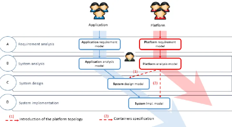
Ori-ented Efficient Engineering. The hHOEi2 method is organized around four models and three refinements, that defines a set of successive activities with clear in-puts and outin-puts – See Fig. 1 [1, 2, 3]. These models are built as follows: (A) The informal requirements are formalized in the Requirement Model by means of System, Actors, Use Cases and Scenarios; (B) This requiement model is then refined into an executable, platform independent, Analysis Model. This is done by means of Hierarchical Opening of objects:
replac-ing an object viewed as black box with several object that represent a more detailed version of the orginal object while collectively exhibiting the same apparent behavior. This transformation can be applied recur-sively to new objects. (C) The Platform is partially introduced by declaring its Worlds – See (1) in Fig. 1. A world is an abstraction of an execution domain that can Hosts objects – like a set of processors and their shared memory, a FPGA, or a dedicated hardware In-tellectual Property (IP). Once the platforms’s worlds are known, the Design Model is built. For this, each object from the analysis model is split in smaller ob-jects that are Distributed over the platform’s worlds. (D) Further platform details are introduced into the application: for each world, its Containers are pro-vided. Each container embodies a set of coding rules, with a trade-off, to implement an object semantics on the target world. The Implementation Model is built by Injecting each object of the design model into a container.
In terms of associated process management, we de-fine the following concepts:
• Task, Phase and Task Sheets: A task is an atomic modeling activity: one of the three refinements applied to a single objet. A phase is the set of tasks that captures all the refinements that build the phase’s model. A task sheet is an instance of a task.
• Participant : A participant may be either a Project Manager (PM) or a Developer. A PM creates and drives the project by (a) defining and assigning tasks to Developers, and (b) by integrat-ing, or rejectintegrat-ing, the models they produce. A De-veloper can modify models only according to a task sheets provided by the PM.
• Project : A project contains its task sheets and the four phases of the process. A project is led by a single PM and built by several Developers. • Iteration: An iteration is a collection of tasks. It
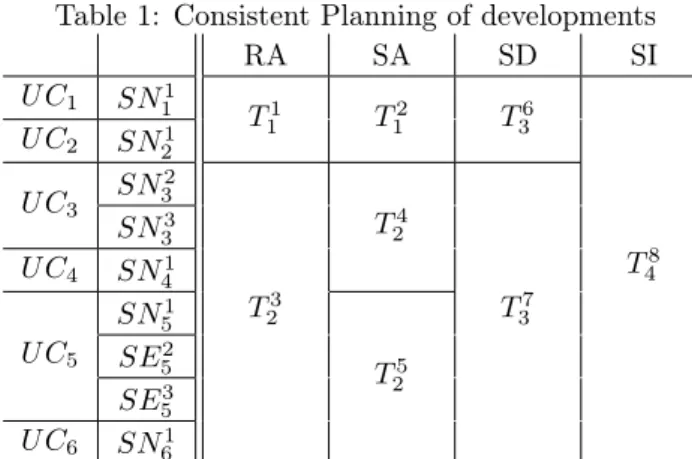
is the smallest entity of project management. Table 1 illustrates an example of a consistent plan-ning using the iterations as a diagram similar to a
Table 1: Consistent Planning of developments
RA SA SD SI U C1 SN11 T1 1 T12 T36 T8 4 U C2 SN21 U C3 SN2 3 T3 2 T4 2 T7 3 SN3 3 U C4 SN41 U C5 SN51 T5 2 SE2 5 SE53 U C6 SN61
Figure 2: hHOEi2 Action Language
Gantt where Ti
j denotes the ith task of iteration j.
The same kind of planing can be declined for the de-velopment of the platform. As can be seen, the itera-tions form rectangles and squares in the table schedule: Each iteration starts from a consistant state and ends by a consistant state of the system. However, this kind of representation does not illustrate the refinements within a single iteration.
3.2
hHOEi
2– A New Action Language
for HSM
The hHOEi2 language build on a number of concepts from Unified Modeling Language (UML) such as ob-jects and associations [4, 15]. hHOEi2Objects
commu-nicate through exchange of messages. Their behavior is captured by Harel’s Statecharts [5, 15]. The hHOEi2
language proposes a number of extensions to UML: • A new Action language. The hHOEi2 action
lan-guage separates actions into two sequentially or-dered parts: First the parallel updates of associa-tions, followed by a parallel sending of messages – See Fig. 2.
• Using associations to define Iteration domains and Indexes. hHOEi2introduces a syntax for the spec-ification of parallel iteration domains for associa-tions updates and sending acassocia-tions.
• Indexed regions: Iteration domains can also be used to enumerate parallel regions. Each region is identified by its own index.
• Transaction: The concept of interface is extended with the ordering and direction of messages ex-changed.
These extensions are detailled by Llopard et al. [4].
4
The CanHOE2 Tool
As we explained previously, CanHOE2 serves to sup-port the hHOEi2process and language. We choose to develop our tool with the several Eclipse technologies [16, 17, 18]. Eclipse offers a set of convenient user-interface components in the context of meta-modeling (Perspective Management, Common Navigator Frame-work, Ecore Standard, etc.). It provides some tools to easily display multieditors in the editor area, navigator and views. CanHOE2 can create models and diagrams associated to these models. Models are created using
January 27–29, 2016 ERTS2 2016 Toulouse, France
Figure 1: hHOEi2 a Collaborative Top-Down Dev. Process for Embedded System Design: Application and
Platform Tracks
the Eclipse Modeling Framework (EMF) tool. It al-lows to instantiate models by providing a meta-model and save them in XML Metadata Interchange (XMI) markup language. It is suitable for metamodels and model exchanges. CanHOE2 also offers a textual edi-tor for the hHOEi2language. In this section, we detail
the implementation choices, interface design and con-tributions of our tool.
4.1
Tool Design
CanHOE2 provides four editors corresponding to the four models described in the hHOEi2 method (see
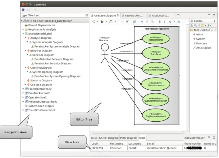
Fig. 1). Navigation in the models is based on the logical ordering of refinements within models. The project management tool supports consistent planning and definition of iterations obeying the model refine-ment dependencies. The iteration history is navigable. The user interface is split into three areas at a mini-mum (see Fig. 3):
• The Navigator Area, that allows the designer to intuitively navigate inside a streamlined hierarchy of hHOEi2 artefacts.
• The Editor Area: where the developer can write program using graphical elements or textual cod-ing.
• The View Area, dedicated to project management and teamwork tools. It implements dedicated views to update information about the entities se-lected in the active editor.
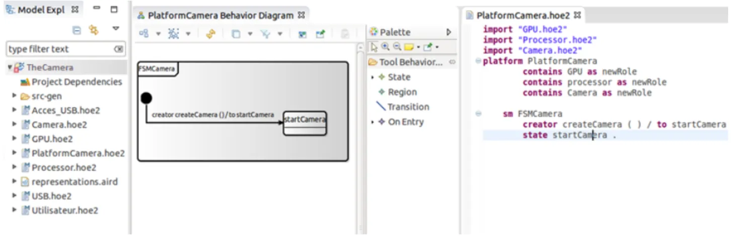
As illustrated in Fig. 4, the developer may either write its program directly in hHOEi2 textual language or describe it graphically, assisted by a palette and a property panel: a palette is displayed and the devel-oper is able to drag and drop entities from it. Infor-mation about graphical entities can be modified in the graphical editor, or in a property panel. Graphic and textual development can be complementary. Indeed, the developer can mix user friendly textual and graph-ics solutions, they will be automatically synchronized to each backup (see Fig. 4). By double-clicking on any graphical element, an embedded hHOEi2language edi-tor open up and let the programmer modify the actual code (see Fig. 5).
Figure 5: Embedded Editor for Transition
4.2
Tool Implementation
The first step is to derive a well-formatted Ecore meta-model from our canonical one. This step is fundamen-tal since we need to consider the Ecore and its asso-ciated tool specificities. Once we have produced our
Figure 3: The CanHOE2 Interface Dedicated to the hHOEi2Method and Language
Ecore metamodel, we defined the hHOEi2 language
syntax using Xtext/Xtend technology from the above defined Ecore model [17]. Xtext provides a set of tools for the implementation of domain-specific languages. From the hHOEi2 metamodel, we derived a full
con-crete implementation of it. The compiler components of our language are independent of Eclipse or OSGi and can be used in any Java compliant environment. Xtext automatically generates the parser, a type-safe builder of our Abstract Syntax Tree (AST), the seri-alizer and code formatter, the scoping framework and the text editor. The editor integrates syntax highlight-ing and error checkhighlight-ing, among many other thhighlight-ings. To achieve graphical models, we rely on the Sirius frame-work [18]. Sirius enables the visual design of complex systems (software, business activities, physics, etc.) and guarantees the consistency of the corresponding data (architecture, component properties, etc.).
4.3
Support Tools for Project
Manage-ment in CanHOE2
CanHOE2 offers several tools to support project man-agement. Indeed, it can manage the authentification and collaborative work providing a global view on the progress of the project.
Authentication. In a regular work environment, an employee can only access the projects to which he has been assigned. In CanHOE2, once authenticated, the user accesses a personal dashboard that lists the projects in which he is involved. From this dashboard, he can also create new projects as a PM. According to his role in the project, one of two perspectives is opened: “Project Manager” or “Developer” perspec-tive. A perspective is a window with adapted views to the user. Eclipse RCP can easily manage these per-spectives and allow us to show a proper layout of the available views. The views in CanHOE2 are based on Java SWT [19].
The user authentication process goes through Lightweight Directory Access Protocol (LDAP). LDAP is a network protocol for accessing an electronic direc-tory where you can reference the users (name, login, phone ...), machines or applications. Access to LDAP server is done via Java Naming and Directory Interface (JNDI) [20].
Collaborative development. Such a collabora-tive environment needs a database to capture all the artifacts manipulated and their evolution over time. CanHOE2 uses centralized Git repositories to this end that are accessed by CanHOE2 on behalf of each par-ticipant [21]. CanHOE2 uses two types of repositories: • A configuration Git repository contains the
infor-January 27–29, 2016 ERTS2 2016 Toulouse, France
Figure 4: CanHOE2 Synchronized Text and Graphical Editors
mation that CanHOE2 uses to connect to LDAP and the list of all CanHOE2 active repositories. • Several project-specific Git repositories, where we
store additional information about the project (task sheets) and resulting patterns of the Can-HOE2 application (model use cases, scenarios). Project monitoring. In order to help the project manager to monitor the project development and to plan different iterations on it, we implement traditional diagrams for project management such as GANTT and PERT diagrams. Internalized project management re-duces development time and provides a monitoring in-terface to better manage the development team.
5
Case Study
In this section, we introduce a Face Tracker system. The face tracker system consists of application for face detection, which is hosted by an Oriented Camera plat-form. This platform includes a general purpose pro-cessing unit, a Passive InfraRed (PIR) sensor and a bracket on which the camera is attached. Two servo-motors orientate the bracket for pan and tilt.
Fig. 3 illustrates use cases diagram of the Face Tracker application . Tables 2 and 3 show multiple use cases and scenarios, respectively, that formalizes the requirements. From these use cases and scenarios, we can now define a task list and its corresponding order of execution. We present hereafter a non-exhaustive list of tasks that have to be performed:
• T1: Refinement of UC 1 & 2
• T2: Initiation of the system analysis
• T3: Refinement of UC 3, 4, 5 & 6
• T4: Refinement of the system analyis for UC 3 &
4
• T5: Refinement of the system analyis for UC 5 &
6
• T6: Initiation of the system design
Table 2: Usecases of the Face Detection Application
Id Causality Name Description
1 Primary Detect presence The actor wants to know when somebody enter the monitored zone.
2 Primary Track faces The actor wants to track faces of people entering the moni-tored zone.
3 Secondary Toggle camera control The actor wants to switch between manual and automatic tracking modes
4 Secondary Query camera control mode The actor wants to know the current tracking mode
5 Secondary Orientate camera The actor set the camera’s orientation.
6 Secondary Query camera orientation The actor wants to know the camera’s curent orientation.
• T7: Refinement of the system design
• T8: System implementation
Once this list is completed, we can define the execu-tion priority of tasks and hence the list of our different iterations.
• I1= T1 + T2 : Refinement of the use cases 1 & 2
and system analysis initiation
• I2= T3 + T4 + T5: Refinement of requirements
and system analysis
• I3= T6 + T7: System design
• I4= T8 : System implementation
Table 1 illustrates our iterations planning. In what follows, we will focus on I1and I3iterations. However,
before the beginning of the design phase (i.e. iteration I3), the platform development team have to start to
work on it. We will call that iteration I10. We named our platform, "The Oriented Camera platform".
Table 3: Scenarios of the Face Detection Application
Id Nature Name
Description
1-1 Nominal Presence detected notification The actor subscribes for updates of presence in the monitored zone. The application notifies to the user when somebody enters or exit the monitored zone. The actor unsubscribes when he does not want updates anymore.
2-1 Nominal Face tracking notification The actor subscribe to people’s faces and the position in the monitored zone. The application notifies to the user with the position of a face in the monitored zone every 2 s. The actor unsubscribes when he does not want to track people faces anymore.
3-1 Nominal Switching to automatic mode The system is in manual mode. The user toggles it to auto-matic mode.
3-2 Nominal Switching to manual mode The system is in automatic mode. The user toggles it to manual mode.
4-1 Nominal Querying control mode The actor asks for the camera’s control mode. The system answers wether the camera is in automatic or manual mode. 5-1 Nominal Manually orienting the camera The system is in manual mode. The user wants to move the camera relative to the curent position. The camera is moved by the requested pan and tilt angles.
5-2 Error Manually orienting while in auto. mode The system is in automatic mode. The user wants to move the camera relative to the curent position. The system refuses because the camera is in automatic mode.
5-3 Error Manually orienting the cam. hits a stop The system is in manual mode. The user wants to move the camera relative to the curent position. The camera is moved by less than the requested pan and tilt angles as it hits a hard stop.
6-1 Nominal Camera position query The actor asks the system about the camera position. The system answers with the position.
Iteration I1: Refinement of the use cases 1&2
and system analysis initiation
During this iteration, we can detail the use cases identified but also initiate the analysis phase. Fig. 6 illustrates an analysis model of the Face Tracker sys-tem : the syssys-tem is composed by three objects (1) a presence detector for detecting a presence in a specific area, (2) a face detector for detecting a face and its po-sition from a video stream and (3) a turret controller for controlling the orientation of a camera a control-lable turret two angles.
In this iteration we have also to model the behav-ior of our application, and its response to exchanged messages (See Fig. 7).
Iteration I10: Requirements and system
anal-ysis of the platform
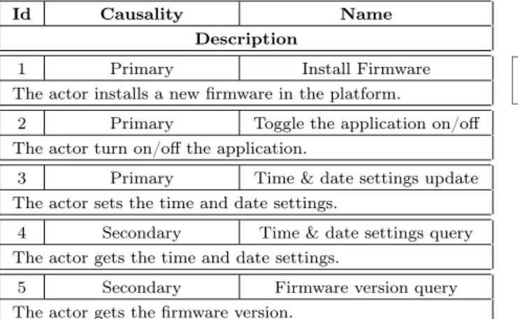
Tables 4 and 5 gives a list of use cases and scenar-ios of the platform. These lists can be completed and refined with theirs corresponding diagrams.
To model the platform, we use the same diagram for
Figure 6: Face Tracker system opening diagram
Figure 7: Face Tracker system behavior diagram
modeling the application with a particular notation for the different elements of the platform. Fig. 8 shows the analysis model of the platform. This platform allows the hosted application to control, via two engines, the position of the camera by orientating it around two axes. The model is composed by two worlds a Pro-cessor and Microcontroller. They are provided with resources in terms of computing and memory, and com-munication. They also provide different containers al-lowing access to the communication resources and to the peripherals of the platform.
The technical choices for the platform design are: • The Raspberry PI platform: It is adapted to the
field of image processing and allows installing and uninstalling Python programs running one pro-gram at a time. It allows also the update of time and date settings.
• The turret control platform: This platform pro-vides the use cases (1) subscribtion to presence detection, and (2) turret orientation. The turret can be used to support the sensors or actuators, such as a camera, an ultrasonic radar, a projector, etc.
• The Arduino UNO platform: It is a prototyping platform for the control of sensors and, digital or analog actuators.
From these three platforms we have designed the com-position diagram (see Fig. 9). From this level of mod-eling we can start the system design.
January 27–29, 2016 ERTS2 2016 Toulouse, France
Table 4: Use cases of the Oriented Camera platform
Id Causality Name Description
1 Primary Install Firmware The actor installs a new firmware in the platform.
2 Primary Toggle the application on/off The actor turn on/off the application.
3 Primary Time & date settings update The actor sets the time and date settings.
4 Secondary Time & date settings query The actor gets the time and date settings.
5 Secondary Firmware version query The actor gets the firmware version.
Table 5: Scenarios of the Oriented Camera platform
Id Nature Name
Description
1-1 Nominal Firmware installed The actor installes a new firmware.
1-2 Error Firmware installation error A firmware is already installed on the platform. The actor wants to install the same version or an older version of the firmware. The firmware cannot be installed.
2-1 Nominal Toggle the application on/off The actor turn on the application. The application runs till the actor decides to turn off the application. The application is switched off.
3-1 Nominal Time & date settings updated The actor sets the time & date. The platform reset its clock to the entered time & date.
4-1 Nominal Time & date settings query The actor asks the system about the time & date. The system answers with its internal time & date.
5-1 Nominal Firmware version query The actor asks the system about the firmware. The system answers with the firmware version.
The I3iteration initializes and starts the system
de-sign phase satisfying the separation of objects, into the two worlds of the platform (See Fig. 10).
6
Conclusion & Perspectives
The hHOEi2 method defines a single process used to develop both applications and platforms. It de-fines precisely what information is sent from the plat-form model to the application model during develop-ment. Its companion language suports parallelism and is amendable to polyhedral analyses. It is made of (1) a new action language limited to association updates and sending of messages, (2) domains, iterators and indexes based on associations.In this paper, we presented CanHOE2, a modelling and process management tool for the hHOEi2 method
and its language. Its main contribution is that not only does it supports the hHOEi2 language, as any
modelling tool, but also the associated process. The
Figure 8: Oriented Camera Platform Analysis
Figure 9: Oriented Camera Platform Composition
Figure 10: Face Tracker system design
support of management and cooperation is deeply in-tegrated with support of modeling.
In future work, we want to extend CanHOE2 with more support for the method, in particular towards the models simulation and hHOEi2model-to-model trans-formations.
Aknowledgements: This work was partially funded by the Artemis-JU and the French “Min-istère de l’économie, de l’industrie et du numérique” for the Artemis project COPCAMS, GA 332 913, http://copcams.eu.
References
[1] Nicolas Hili, Christian Fabre, Sophie Dupuy-Chessa, and Stéphane Malfoy. “Efficient Em-bedded System Development: A Workbench for an Integrated Methodology”. In: Proc. of the 6th Embedded Real-Time Software and Sys-tems Congress (ERTS2 2012). Toulouse, France,
Feb. 1, 2012. url: http://hal.inria.fr/hal-00671966/.
[2] Nicolas Hili, Christian Fabre, Sophie Dupuy-Chessa, and Dominique Rieu. “A Model-Driven Approach for Embedded System Prototyping and Design”. In: Proc. of The IEEE International Symposium on Rapid System Prototyping (RSP 2014). New Delhi, India, Oct. 16–17, 2014. doi: 10.1109/RSP.2014.6966688.
[3] Nicolas Hili, Chrisitan Fabre, Ivan Llopard, Sophie Dupuy-Chessa, and Dominique Rieu. “Model-Based Platform Composition for Embed-ded System Design”. In: Proc. of IEEE 8th In-ternational Symposium on Embedded Multicore Many-core Systems-on-Chip (MCSoC-14). Uni-versity of Aizu, Japan, Sept. 23–25, 2014. doi: 10.1109/MCSoC.2014.31.
[4] Ivan Llopard, Albert Cohen, Christian Fabre, and Nicolas Hili. “A Parallel Action Language for Embedded Applications and Its Compilation Flow”. In: Proceedings of the 17th International Workshop on Software and Compilers for Em-bedded Systems. SCOPES ’14. Sankt Goar, Ger-many: ACM, 2014, pp. 118–127. isbn: 978-1-4503-2941-5. doi: 10.1145/2609248.2609257. [5] David Harel. “Statecharts: a Visual Formalism
for Complex Systems”. In: Science of Computer Programming 8.3 (1987), pp. 231–274. issn: 0167-6423.
[6] Sébastien Gérard. “Modélisation UML exé-cutable pour les systèmes embarqués de l’automobile.” PhD thesis. Université d’Evry, Oct. 2000.
[7] Denis Aulagnier et al. “SoC/SoPC development using MDD and MARTE profile”. Anglais. In: Model Driven Engineering for Distributed Real-time Embedded Systems. Ed. by Jean-Philippe Babau et al. ISTE, Mar. 2009.
[8] A. Basu et al. “Rigorous Component-Based Sys-tem Design Using the BIP Framework”. In: Soft-ware, IEEE 28.3 (Apr. 2011), pp. 41–48. issn: 0740-7459. doi: 10.1109/MS.2011.27.
[9] IBM Rational. Rhapsody. url: http : / / www . ibm . com / software / products / en / ratirhap (visited on 2015-10-13).
[10] IBM Rational. Rules Composer. url: http:// www- 01.ibm.com/support/docview.wss?uid= swg27019384 (visited on 2015-10-13).
[11] Sébastien Gérard, Cédric Dumoulin nad Patrick Tessier, and Bran Selic. “Papyrus: A UML2 tool for Domain-Specific Language Modeling”. In: vol. 6100. Springer Verlag, 2010.
[12] Sébastien Gérard. On the Papyrus’ USE: Us-age, Specialization and Extension. Sept. 6, 2010. url: http : / / www . eclipse . org / modeling / mdt / papyrus / usersTutorials / resources / TutorialOnPapyrusUSE_d20101001.pdf. [13] Eclipsepedia. Papyrus Qompass. June 5, 2014.
url: https : / / wiki . eclipse . org / Papyrus % 5C_Qompass.
[14] Eclipsepedia. Papyrus/Codegen/Cpp descrip-tion. Sept. 29, 2015. url: https : / / wiki . eclipse . org / Papyrus / Codegen / Cpp % 5C _ description.
[15] Object Management Group. OMG Systems Mod-eling Language (OMG SysML), Version 1.3. Ob-ject Management Group, 2012.
[16] Eclipse. The Eclipse Foundation. url: http:// www.eclipse.org (visited on 2015-10-13). [17] Xtext: a Framework for Development of
Pro-gramming Languages and Domain Specific Lan-guages. Eclipse Foundation. url: http://www. eclipse.org/Xtext (visited on 2015-10-13). [18] Sirius: an Eclipse Project which Allows the
Creation of Graphical Modeling Workbench by Leveraging the Eclipse Modeling Technologies. Eclipse Foundation. url: http://www.eclipse. org/sirius (visited on 2015-10-13).
[19] SWT : an open source widget toolkit for Java designed to provide efficient, portable access to the user-interface facilities of the operating sys-tems on which it is implemented. Eclipse Foun-dation. url: www.eclipse.org/swt/ (visited on 2015-10-27).
[20] Java Naming and Directory Interface. Oracle. url: http://www.oracle.com/technetwork/ java/jndi/index.html (visited on 2015-10-13). [21] Git: a Free and Open Source Distributed Version Control System. git. url: http://git-scm.com (visited on 2015-10-13).