HAL Id: hal-01203435
https://hal.archives-ouvertes.fr/hal-01203435
Submitted on 23 Sep 2015
HAL is a multi-disciplinary open access
archive for the deposit and dissemination of
sci-entific research documents, whether they are
pub-lished or not. The documents may come from
teaching and research institutions in France or
abroad, or from public or private research centers.
L’archive ouverte pluridisciplinaire HAL, est
destinée au dépôt et à la diffusion de documents
scientifiques de niveau recherche, publiés ou non,
émanant des établissements d’enseignement et de
recherche français ou étrangers, des laboratoires
publics ou privés.
Distributed under a Creative Commons Attribution| 4.0 International License
From Functional Analysis to CAD Modelling Based on
Knowledge Transformation Driven by the Design
Process
Medhi Iraqi, Lionel Roucoules
To cite this version:
Medhi Iraqi, Lionel Roucoules. From Functional Analysis to CAD Modelling Based on Knowledge
Transformation Driven by the Design Process. 9th International Conference on Product Lifecycle
Management (PLM), Jul 2012, Montréal, Canada. pp.458-467, �10.1007/978-3-642-35758-9_41�.
�hal-01203435�
is an open access repository that collects the work of Arts et Métiers ParisTech
researchers and makes it freely available over the web where possible.
This is an author-deposited version published in: http://sam.ensam.eu
Handle ID: .http://hdl.handle.net/10985/10127
To cite this version :
Medhi IRAQI, Lionel ROUCOULES - From Functional Analysis to CAD Modelling Based on Knowledge Transformation Driven by the Design Process - In: Conference PLM 2012, Canada, 2012-07-09 - Conference PLM2012 - 2012
Any correspondence concerning this service should be sent to the repository Administrator : [email protected]
L. Rivest, A. Bouras, and B. Louhichi (Eds.): PLM 2012, IFIP AICT 388, pp. 460–469, 2012. © IFIP International Federation for Information Processing 2012
From Functional Analysis to CAD Modelling
Based on Knowledge Transformation Driven
by the Design Process
Mehdi Iraqi and Lionel RoucoulesArts et Metiers ParisTech, CNRS, LSIS, 2 cours des Arts et Metiers, 13617 Aix-en-Provence, France
Abstract. Most of industries currently spend too much time to find information on
past product design process. This considerably reduces the time it can devote to innovation. The authors assume that the design process meta-model seems very interesting for modelling the design rational and then for accelerating information retrieval. Indeed, the model of the design process partly supports every resources involved in decision making activities (i.e. who, what, when, why, where, how). The authors therefore propose the use of a MBE architecture for driving the product modelling based on the design process model. The UML activity diagrams and the IDEFØ meta-model are linked for supporting automatic generation of product models using specific transformation knowledge. The CAD model is partly generated from the product functional analysis.
Keywords: Design process modelling, Model Based Engineering, CAD
modelling.
1
Introduction
The engineering of mechanical product is a research and industrial activity which studies the design of complex mechanical systems. The design process, that involves the collaboration of various experts using domain specific software, raises syntactic and semantic interoperability issues which are not addressed by existing software solutions or their underlying concepts.
The second section of the paper depicts the research context based on engineering design, knowledge and data modelling supported by the CAx and PLM software. It then presents some current issues for linking the functional model to the CAD model in order to track the design rationale.
Section three introduces, on the one hand, how design process modelling is necessary to really understand the design rationale across the time. On the other hand, the design process is also used to drive interoperable data transformations in order to assure data propagation in case of design changes.
Section four proposes a flexible model-based software architecture that allows for a federation of experts to define and collaborate in innovative design processes. This interoperable architecture is based on “projection” of models from specific commercial
software to a model backbone that is used to “transform” one model to another. The federation of expert’s models is used to create strong link among functional model and CAD model.
Section five finally presents how the design process model can drive the product model transformations in order to support engineering activity. Indeed those transformations generate expert’s models automatically and can be used in case of any design changes. The presented approach is illustrated by its implementation on an academic use case that shows how part of the CAD model can be created automatically from the functional modelling. The design process is then seen as knowledge synthesis process instead of as CAD centric process.
Conclusion and recommendations for further work are therefore presented.
2
Current Issues to Support Engineering Design Rationale
The mechanical product engineering is a domain which studies the entire lifecycle of a complex mechanical system from the customer requirements analysis to its end of life. It involves several phases: design, industrialisation, production, exploitation, dismantling, recycling.
The design phase is the activity that aims at creating a complete digital mock-up including all information on the product coming from multiple points of view: functions, components, form features, materials, multi-physical behaviours, etc. [1, 2]. This strongly knowledge-based and collaborative activity involves many partners with different expertises, each of them using very specialized computer tools, in their turn based on different knowledge representations and on operational procedures.
One of the Main Industrial Issue with Respect to Design Process Is to Retrieve What Have Been the Decisions Taken in Past Projects. This retrieval phase is
currently timeconsuming whereas it does not bring any added value. Moreover it is hard to find all the detail of the decisions. In order to know the rationale of engineering activities, a fundamental issue remains in tracing every actor, every method, and every decision that have been implicated in every choice of the design process. The authors argue that those details could be formalized using a 6W approach that is mainly used to write histories, to treat problems analysis or in quality management methods: who, what, where, when, why and how [3].
Such approach would provide a lot of benefits in engineering design in order to find the information used in past design process. During new design process, this faster information search will accelerate phases which are unchanged in order to
focus on phases that will provide innovation. Another added value concerns the
learning approaches in industry in order to faster the acquisition of best practices with respect to industrial design process.
So far most of the modelling approaches and most of the current computer-supported tools aim at capturing data related to the designed product. That only represents the “what” of the 6W approach. According to [4], integrated design process and product model is a good way to tackle the mentioned issue concerning product design rationale. The present paper goes to the same objective to link the design
process model and the product model, nevertheless it provides more flexible and dynamic support based on a MBE (Model-Based Engineering) architecture.
462 M. Iraqi and L. Roucoules
3
Design Process Modelling
A lot of process meta-models have been proposed during those last decades. Based on [5] the authors argue that those models are providing adequate concepts to tackle the issues introduced before:
• IDEF meta-model is based on ICOM concepts: Input, Control, Output and Mechanisms [6]. They are closed to 6W concepts. The “what” can be supported by I/O, “Who, How, Why” can be seen as Resources or Mechanism of IDEF. Finally the “When” is implicit to the meta-model that provides sequential links among the process activities.
• UML activity diagram [7] also provides concepts related to the design process (activity, data flows, synchronisation bar, pin that represents UML objects ...). However its applications are more dedicated to talk and flows process usually used in manufacturing system control for example.
• BPMN provide also concepts with respect to process [8]. It will not be more details since the activity diagram is very similar to UML one: data flows and control flows.
As written by [9] a process can be classified in three categories: creative, interactive and automatic. Those three categories rank the level of autonomy in running a process. The authors argue that a design process is a creative process since the design process of a complex system is not known when the design starts. The process is created dynamically.
Both IDEF and UML Concepts Are therefore Exploited in This Paper through Complementary Manner. The first one is used in order to treat business model with
information related to the design rationale (i.e. 6W) that are more based on data flow needed in decision making activities. The second one is used in order to treat explicit information (i.e. data related to the designed product) which can be partly processed automatically since UML provides strong control flows concepts. That proposal is detailed in section five after the presentation of the MBE (model-Based Engineering) architecture.
Figure 4 will show an IDEF model that drives an UML one which therefore triggers some automatic product model transformations. A soon as the IDEF model evolves, the transformations also evolve dynamically. The IT system is then strongly flexible with respect to the design process evolution.
4
MBE Architecture for Virtual Product Design
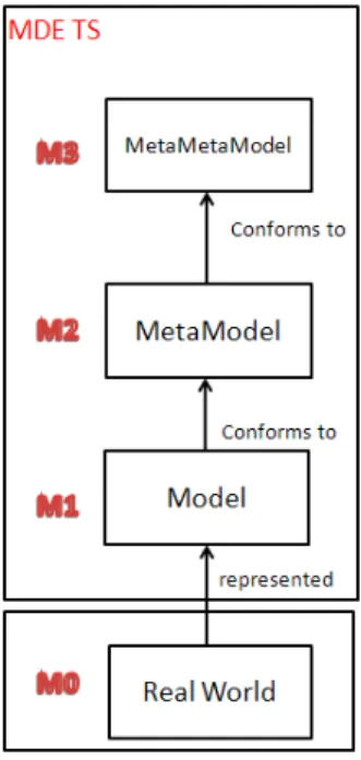
Model-based engineering (MBE) [10] is a methodology that provides tools, concepts and languages to create and process models. The main principles of the four levels of the MBE architecture are represented in Figure 1.
A model is a view or a representation of a real system (M0) that captures some characteristics of that system and provides knowledge about it. MBE offers a large variety of tools (and languages) that enables us to create, process and exchange
knowledge between different models expressed in precise meta-models. The syntactic rules used to express a model are called a meta-model. The latter is expressed in a unique self-descriptive meta-meta-model. To understand the concept of conformity shown in Figure 1, a model (M1) is conformed to a meta-model (M2) if and only if all elements of this model are defined by the meta-model.
Fig. 1. Representation of the four-level architecture of MBE
MBE offers a number of advantages such as cost reduction throughout the product (ex: software) life cycle. It reduces development time for new products and provides platform independence by modelling specifications independently of technologies.
The main idea of MBE is to define a declarative architecture in order to focus on the studied concepts and the links between them independently of the tools used to create these concepts. An implementation of MBE can be found in Eclipse Modelling Framework (EMF). EMF [11] is a modelling framework for building tools and data-processing based on models.
As shown on Figure 2, a model transformation [12] is the generation of one or more target models from one or more source models according to a set of transformation rules. These rules describe how a model described in a source language can be transformed into a model described in a target language. These models (target and source models) are described in one or more meta-models.
464 M. Iraqi and L. Roucoules
Fig. 2. The model transformation principles
A technical space (TS) [10] is a set of techniques, principles, syntactic rules and tools associated to a particular format or domain (specific area). MBE provides an approach that integrates homogeneously various technical spaces through an operation to obtain models corresponding to these data and vice-versa. A general representation of the different levels of a particular TS (XML, ontologies, etc.) is represented in figure 3.
4.1 Application of MBE in Product Design
MBE provides a solution in order to represent knowledge carried by different expert languages as models. The authors therefore consider that data created by a design expert in a particular TS and useful to other expert in another particular TS can be modelled and linked in an MBE environment (i.e. MBE TS) [13]. Product design may then benefit from many advantages that an MBE approach can provide, such as:
• A management of relations between models that is independent of design expert tools. This management is indeed achieved in the MBE TS and supports:
o More easily the substitution from a design expert tool to another. o the flexibility related to modelling languages that will enrich the
transformation among semantic models
• The possibility to dynamically implement the IT system with respect to a specific design process. That is the objective of the following section 5.
5
Product Modelling Driven by the Design Process
5.1 Use Case Description
The paper illustrates the added-value of such approach on an innovative design scenario. The use case, deals with the design of a mechanical coupling system between a plane propeller and a diesel engine. The design process aims at obtaining a description of a CAD product assembly from its functional and energetic analysis.
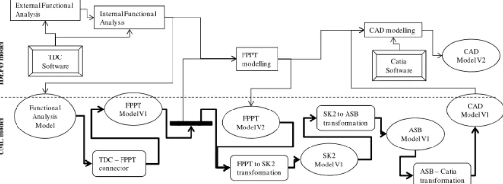
Figure 4 outlines the activities (rectangular boxes) of the design process linked with data flow (arrows). The design process leads the software tools (double line rectangular boxes) and the knowledge models (ellipses) used in the scenario. As presented in section 4, those knowledge models are driven by models transformation (rounded rectangular boxes). The coherency between the IDEF and UML process models is detailed in section 5.6. The bold arrows represent the software connectors and the knowledge transformations automatically run (i.e. talk and flow process) based on the the IDEF process. The following subsections detail each operation.
Fig. 4. Illustration of product modelling driven by the design process and specific models
transformations supported with the MBE architecture
Externa l Functiona l
Ana lysis Interna l Functiona l
Ana lysis FPPT modelling CAD modelling ID E F Ø mo d e l UM L m o d e l FPPT to SK2 transforma tion TDC – FPPT connector SK2 to ASB tra nsformation ASB – Ca tia tra nsforma tion FPPT Model V1 FPPT Model V2 SK2 Model V1 ASB Model V1 CAD Model V1 TDC Software Ca tia Softwa re Functiona l Ana lysis Model CAD Model V2
466 M. Iraqi and L. Roucoules
5.2 Architecture Implementation
The authors have chosen the Eclipse EMF platform [11] as the implementation framework, mainly for its maturity and tools support. ECORE is used as the meta-meta-model language. The use case files, models and transformations are open source and can be freely downloaded from a single package [14]. In the following, meta-models will be represented using ECORE diagrams.
5.3 Knowledge Models
The scenario that is presented uses three specialized models which are briefly introduced below. Every detail can be found in [13].
FPPT stands for Function, Physical Principle, and Technology. Informally described
in [15], the authors created a meta-model which covers most of its concepts. Functions refer to abstract product functionalities, which may be divided into sub-functions. Terminal functions are realized, through a physical principle, by a specific (known) technology.
SK2 stands for Skins, Skeletons, informally described in [15]. Briefly, product parts
have external skins which can be linked to other skins. The product skeleton, which represents the energy flows, is made of external functions between those skins, and internal functions inside the parts. Each function has energetic properties.
ASB stands for product ASemBly. This very simple meta-model, in which the system
is simply viewed as a set of interconnected parts, has been created specifically for this scenario, as an intermediate knowledge model between SK2 and the CAD tool CATIA.
5.4 TDC – FPPT Connector
The functional analysis tool selected for the use case is TDC [16]. The tool provides an export of its data as an XML file. The authors used EMF native facilities to obtain the ECORE meta-model from the provided XML schema and the associated injection/extraction operation. However, due to XML breakdown restrictions, the associative references of the schema are simulated through the equivalence of textual properties (IDs). The authors thus created an additional model transformation, using ATL, to a target meta-model where associative references are restored.
The final step to the connector is an ATL transformation which targets the FPPT meta-model. The transformation involves a loss of knowledge which is not relevant for other experts in the context of our collaborative scenario.
FPPT to SK2 Transformation
This ATL transformation mainly consists of two parts:
• a mapping from FPPT's functions and technologies to SK2's external functions and parts.
• a characterization of the skeleton energetic properties obtained from FPPT's physical principles.
SK2 to ASB Transformation
This very simple ATL transformation uses SK2's knowledge to create an assembly where different product parts are linked according to the skeleton.
5.5 ASB to CATIA Connector
The selected geometrical modelling tool is CATIA [17]. Among the possible formats for importing data, CATIA proposes the use of STEP AP203 [18], an industry standard for exchanging geometrical information about a mechanical product.
The STEP standard defines textual files which conform to a STEP schema (Application Protocol here AP203), which in turn is defined using a relational language called EXPRESS [19]. The OMG had already considered the interoperability between STEP files and MOF models in the original XMI proposal.
Two alternatives were envisioned:
• a meta-meta-model mapping between EXPRESS and MOF, if any is possible due to the semantic gap.
• a meta-model mapping between a specific STEP schema and its counterpart meta-model.
To the best of authors’ knowledge, the first option has been worked on by various projects but is not yet mature nor known feasible in the general case. They thus chose the second option.
Technically, XTEXT/XPAND [20] is used to define the STEP grammar and generated the corresponding meta-model. This state-of-the-art technology allows us to inject and extract STEP files to/from STEP models.
For the sake of clarity, authors separated the STEP general meta-model from the AP203 schema meta-model (which contains most of the product information).
A first ATL transformation generates an AP203 model from our assembly knowledge model (ASB). In order to obtain the general STEP model, a second ATL transformation takes two models as source: the AP203 model and a custom model which only contains necessary header information for the STEP file (such as document creator, date, etc.).
5.6 Product Modelling Driven by the Design Process
Based on the assumption presented in section 3 that argues an adequate link among IDEF and UML modelling, figure 4 shows:
• the design IDEF process of the presented use case. This process model embeds on the one hand, informal information encapsulated in files that explain the choices that are made (i.e. design rational). On the second hand, each activity of the process is related via the I/O of the formal product model (cf. section 3). • the UML process that supports explicit knowledge transformations triggered
by IDEF activity. Those transformations are totally transparent for the designer which only defines the IDEF process. Since the two process models are linked, the knowledge models are partly automatically created with respect to the definition of the IDEF design process. If the design process evolves, the transformations will also evolve accordingly.
468 M. Iraqi and L. Roucoules
6
Conclusion and Recommendations for Further Work
In order to support the design rational, the authors propose to model design process using IDEF meta-model. Those concepts indeed trace who take decisions, how, when and what is the information concerned. Moreover this process model drives UML activity that automatically creates models from one to others. This provides a new approach in order to support data exchange and to accelerate timeconsuming tasks. This approach is more flexible since it is based on meta-models instead of models (cf. Advantages of MBE in section 4).
The authors have already illustrated this approach on several use cases. They are currently implementing this proposal in EMF (Eclipse Modelling Framework) in order to create a library of models that would be shared to the scientific community.
The final further work will be to define performance indicators to really assess the added value of that research work compared to other solutions.
References
1. Shah, J.J.: Assessment of features technology. Computer-Aided Design 23(5), 331–343 (1991)
2. Yan, X.-T.: A multiple perspective product modelling and simulation approach to engineering design support. Concurrent Engineering Research and Application Journal 11(3), 221–234 (2003)
3. Juran, J.: Quality Control Handbook. Mc Graw-Hill Book Company (1951)
4. Nowak, P., Rose, B., Saint-Marc, L., Callot, M., Eynard, B., Gzara-Yesilbas, L., Lombard, M.: Towards a design process model enabling the integration of product, process and organization. In: IDMME Conference, Bath, UK (2004)
5. WFMC, Terminology and glossary. Technical Report WFMS-TC-1011, Technical report, Workflow Management Coalition Brussels – Belgium (1996)
6. Ross Douglas, T.: Structured Analysis (SA): A Language for communicating ideas. Transactions on Software Engineering SE-3, 19–34 (1997)
7. Fawler, M.: UML distilled. A brief guide to the standard object modelling language. Addison-Wesley (2005)
8. BPMN, Business Process Modelling Notation,
http://www.omg.org/spec/BPMN/index.htm (visited May 2012)
9. Godard, C., Perrin, O.: Les processus métiers: concepts, modèles et systèmes. Lavoisier (2009) ISBN 978-2-7462-2300-4
10. Bézivin, J.: Model Driven Engineering: An Emerging Technical Space. In: Lämmel, R., Saraiva, J., Visser, J. (eds.) GTTSE 2005. LNCS, vol. 4143, pp. 36–64. Springer, Heidelberg (2006)
11. EMF, Eclipse Modeling Framework, http://www.eclipse.org/emf/
12. Czarnecki, K., Helsen, S.: Feature-based survey of model transformation approaches. IBM Syst. J. 45, 621 (2006)
13. Iraqi-Houssaini, M., Kleiner, M., Roucoules, L.: Model-Based (Mechanical) Product Design. In: Whittle, J., Clark, T., Kühne, T. (eds.) MODELS 2011. LNCS, vol. 6981, pp. 548–562. Springer, Heidelberg (2011)
14. Delvion use case (2011),
15. Skander, A., Roucoules, L., Klein Meyer, J.S.: Design and manufacturing interface modelling for manufacturing processes selection and knowledge synthesis in design. International Journal of Advanced Manufacturing Technology 37 (2008), doi:10.1007/s00170-007-1003-2
16. TDC system, http://www.tdc.fr/en/ (visited May 2012)
17. CATIA (Dassault systems), http://www.3ds.com/products/catia/welcome/ (visited May 2012).
18. ISO 10303-203, Industrial automation systems and integration, Product data representation and exchange - Part 203: Configuration controlled 3D designs of mechanical parts and assemblies (1994)
19. ISO 10303-11, Industrial automation systems and integration, Product data representation and exchange - Part 11: The EXPRESS language reference (1994)