UNIVERSITÉ DU QUÉBEC
THÈSE PRÉSENTÉE À
L'UNIVERSITÉ DU QUÉBEC À TROIS-RIVIÈRES
COMME EXIGENCE PARTIELLE DU DOCTORAT EN GÉNIE ÉLECTRIQUE
PAR F ARJS HAMOUD
CONTRIBUTION À L' AMÉLIORATION DES PERFORMANCES D'UNE ÉOLIENNE À BASE DE GÉNÉRATRICE ASYNCHRONE À DOUBLE STATOR
Université du Québec à Trois-Rivières
Service de la bibliothèque
Avertissement
L’auteur de ce mémoire ou de cette thèse a autorisé l’Université du Québec
à Trois-Rivières à diffuser, à des fins non lucratives, une copie de son
mémoire ou de sa thèse.
Cette diffusion n’entraîne pas une renonciation de la part de l’auteur à ses
droits de propriété intellectuelle, incluant le droit d’auteur, sur ce mémoire
ou cette thèse. Notamment, la reproduction ou la publication de la totalité
ou d’une partie importante de ce mémoire ou de cette thèse requiert son
autorisation.
UNIVERSITÉ DU QUÉBEC
THESIS PRESENTED TO
UNIVERSITÉ DU QUÉBEC À TROIS-RIVIÈRES
IN PARTIAL FULFILMENT OF THE REQUIREMENTS OF THE DEGREE OF DOCTOR OF PHILOSOPHY
IN ELECTRICAL ENGINEERING
BY
F ARlS HAMOUD
CONTRIBUTION IN PERFORMANCE IMPROVMENT OF WIND TURBINE BASED DUAL STATOR WINDING INDUCTION GENERA TOR
DOCTORAT EN GÉNIE ÉLECTRIQUE (PH.D.)
Programme offert par l'Université du Québec à Trois-Riv ières
CONTRIBUTION À L' AMÉLIORATION DES PERFORMANCES D'UNE ÉOLIENNE À BASE DE GÉNÉRATRICE ASYNCHRONE À DOUBLE STATOR
PAR
F ARIS HAMOUD
Mamadou Lamine Doumbia, directeur de recherche Université du Québec à Trois-Rivières
Adel Omar Dahmane, président du jury Université du Québec à Trois-Rivières
Ahmed Chériti, codirecteur de recherche Université du Québec à Trois-Rivières
Mohamed Benhaddadi, évaluateur CEGEP du Vieux Montréal, évaluateur
III
Abstract
This thesis is devoted to a new topology of wind energy conversion system based on self-excitation dual stator winding induction generator (SE-DSWIG), driven in variable speed for simultaneous grid-tied and stand-al one applications. SE-DSWIG is a promising technology that shows high efficiency for variable frequency applications in aerospace, maritime, vehicles and for extraction of hydro and wind power; ln the literature, the proposed topologies, especially in variable speed operation, had a weak ability to deal with sudden and large speed variations, which induce voltage collapse and disturb the frequency. Hence, it's imperative to improve the low voltage ride through (LVRT) capability of SE-DSWIG and maintain the power flow at an adequate level even during wind speed variation or gr id disturbance.
The contribution of this dissertation is built on the enhancement of power quality and the improvement of low-voltage ride-through capability of SE-DSWIG. Hence, a multi-converter based unified power quality conditioner (MC-UPQc) is used to sustain the power flow and to mitigate faults. MC-UPQC involves three converters connected back-to-back through an energy storage system. Two of them are connected in series to the SE-DSWIG terminais, while the other converter acts as a D-STA TCOM and connected in shunt to the stator terminal which is linked with the grid. MC-UPQC proved its ability to compensate the supply voltage imperfection, enhance voltage and current at the point of common coupling (PCC) even in the presence ofsudden faults, ameliorate the low voltage ride through (LVRT) capability, and synchronize the generator on the same frequency of the grid.
D-STA TCOM, DVR and UPQC have been evaluated against voltage sag, swell, po or power factor, distorted voltage, unbalanced current and harmonies neutral current. A control strategy based sliding mode has been applied on D-STA TCOM and a simple hysteresis technique was used to control the DVR, while the UPQC was supervised using an adaptive fuzzy logic control technique. The obtained results show high performance of these active compensators against the critical situations.
The SE-DSWIG was investigated in stand-alone and grid-connected operating modes. A multi-converter based unified power quality conditioner (MC-UPQC) has been used to improve the low voltage ride through (L VRT) capability of the generator.
A synchronous reference frame theory is used to supervise the series part of MC-UPQC, while an advanced cascade sliding mode control technique is applied to the shunt part. The analysis of the obtained results leads to conclude that the MC-UPQC ameliorates the performance of the SE-DSWIG in both grid-tied and stand-alone applications. MC-UPQC could compensate the supplied voltage disturbance, enhance voltage quality and current at the PCC even in the presence of sudden faults, ameliorate the LVRT capability, and synchronize the generator on the same frequency of the grid.
v
Acknowledgements
Praise is to Allah by Whose grace good deeds are completed. Praise is to Allah, Lord of the Worlds for his guidance, compassion in difficult moments, and help to finish this work.
Then, 1 would like to express my sincere gratitude to Professor Mamadou Lamine Doumbia, my thesis advisor, for his confidence, advice, availability, support, and contribution to the success of this work. Many thanks for his manner to deal with students, the way he encourages and respects them. Special thanks are expressed to Professor Ahmed Cheriti, thesis co-supervisor, for his availability, constructive criticisms, his encouragement. 1 want to express my grateful also to Nasserdine Boudjerda, Professor at the University of Jijel, Aigeria, for his help, moral support, he has al ways believed in me.
J would like to express my affectionate appreciation to parents for their prayers, unwavenng faith, sacrifices and continuous encouragement to work hard during my academic education. May Allah pro long their lives. 1 want to thank my brothers, my sisters and my family for their unwavering support. This work is especially dedicated to my wife and my daughter Nada, who's with patience and continued support have helped me to carry out this work.
Finally, 1 want to thank ail professors and staff of the electrical and computer engineering department, my colleagues Mohammed, Paul, Bekhada, Allal, Alain Innocent in the laboratory of power quality and energy conversion.
Abstract ... iii
Acknowledgements ... v
Table des matières ... vi
Liste des tableaux ... xv
Liste des figures ... xvi
List of acronyms ... xxiii
Chaptre 1 - Introduction ... 1
1.1 A brief history on the energy ... 1
1.2 Renewable resources: Status and Trends ... 3
1.2.1 Biomass energy ... 3 1.2.2 Geothermal energy ... 4 1.2.3 Ocean energy ... 5 1.2.4 Hydropower energy ... 6 1.2.5 Solar energy ... 6 1.2.6 Wind energy ... 6
VII
1.3.1 Power electronic devices in wind turbine ... 8
1.3.2 Generator in wind turbine ... 9
1.3.2.1 Wound-rotor synchronous generator ... 9
1. 3. 2. 2 Permanent synchronous generator ...... 10
1.3.2.3 Double fed induction generator ...... 10
1.3.2.4 Self-excitation induction generator .......... II 1.3.3 Goals and challenges of Wind turbine industry ... 12
1.3.4 Self-excitation dual stator winding induction generator: State-of-the-art on multiphase generator ... 12
1.4 Research Goals ... 22
1.4.1 Main objective ... 22
1.4.2 Contribution of this thesis ... 23
1.4.3 Publications ... 24
1.4.4 Outline ofthesis ... 24
Chaptre 2 - Field oriented control of a dual stator winding induction motor with indirect speed regulation method ... 26
2.1 Introduction ... 26
2.2 Description of the dual stator winding induction motor ... 27
2.3 Mathematical modeling of DS WIM in biphase system ... 27
2.3.2 Magnetic equations ... 28
2.3.3 Power consumption and electromagnetic torque of DSWIM .. 29
2.4 Dual stator winding induction motor for variable speed application .. 30
2.4.1 DSWIM fed directly from the grid ... .31
2.4.2 DSWIM fed by a voltage source inverter with PWM control.31 2.4.2.1 Modelling of voltage source inverter ...... 31
2.4.2.2 Open loop control of inverters using PWM ...... 33
2.4.3 Vector control of dual stator winding induction motor ... 34
2.4.3.1 Principle of field-oriented vector control technique ... 35
2.4.3.2 Indirect vector control with speed regulation ... 35
2.5 Numerical simulation and results discussion ... .42
2.5.1 Case study #1 ... 42
2.5.2 Case study# 2 ... 44
2.5.3 Case study# 3 ... 45
2.6 Conclusion ... 49
Chaptre 3 - Self-Excited-DSWIG for stand-alone application with passive compensator ... 50
3.1 Introduction ... 50
3.2 Description of SE-DSWIG ... 50
IX
3.3.1 Electric equations ... 51
3.3.2 Magnetic equations ... 52
3.3.3 Excitation capacity bank model ... 53
3.4 Passive compensator ... 53
3.4.1 Passive compensator design for voltage sag ... 54
3.4.1.1 Shunt compensator design ...... 55
3.4.1.2 Series compensator design .... 57
3.5 Modeling of the end-user ... 58
3.5.1 End-user with no-passive compensator ... 58
3.5.2 End-user with shunt passive compensator ... 59
3.5.3 End-user with series passive compensator ... 59
3.6 Numerical results and discussion ... 60
3.6.1 SE-DSWIG performance at no-Ioad condition ... 61
3.6.2 SE-DSWIG performance feeding the end-user in the presence of shunt Pc ... 65
3.6.3 SE-DSWIG performance feeding the end-user in the presence of series PC ... 66
3.6.4 SE-DSWIG performance with a step change in load impedance ... 68
3.6.5 SE-DSWIG performance with a step change in prime mover
speed ... 72
3.7 Conclusion ... 74
Chaptre 4 -Study ofD-STATCOM and DVR for poor power correction, voltage sag and swell mitigation ... 76
4.1 Introduction ... 76
4.2 Distributed Static Synchronous Compensator (D-STATCOM) ... 77
4.2.1 D-STA TCOM configuration ... 78
4.2.1.1 Mathematical modeling of the power system with D-STATCOM 79 4.2.1.2 Phase-Locked-Loop ...... 81
4.2.2 Design of D-STA TCOM components ... 82
4.2.2.1 Estimation of DC-side voltage and capacitor ... 82
4.2.2.2 Estimation of the interfacingfilter ... 83
4.2.2.3 Frequency response of the power system ... ... 84
4.2.3 D-STATCOM operation and control design ... 87
4.2.3.1 SMC application in the inner loop ... 90
4.2.3.2 SMC application in the outer loop ...... 93
4.3 Dynamic Voltage Restorer (DVR) ... 94
XI
4.3.2 Mathematical modeling of the power system with DVR ... 95
4.3.3 Design ofDVR components ... 96
4.3.3.1 lnjected voltage rating ... 96
4.3.3.2 Apparent power of DVR ...... 97
4.3.3.3 Current rating of DVR ... 97
4.3.3.4 DC-side voltage ........................... 97
4.3.3.5 DVR interfacingfilter ... 98
4.3.4 DVR operation and control ... 98
4.4 D-STA TCOM and DVR performance analysis ... 99
4.4.1 Simulation results with D-STA TCOM ... 1 00 4.4.2 Simulation results with DVR ... I 04 4.5 Conclusion ... 108
Chaptre 5 -A Study on the UPQC for power quality improvement.. ... 1 09 5.1 Introduction ... 109
5.2 Topology of the system under study with UPQC ... 112
5.2.1 Description of the system under study ... 112
5.2.2 Mathematical modeling of the system under study ... 113
5.2.3 Phasor diagram ofUPQC ... 114
5.3.1 Control strategy applied on OVR ... 116
5.3.2 Control strategy applied on O-STA TCOM ... 117
5.3.3 Adaptive fuzzy logic controller design ... 121
5.4 UPQC performance analysis ... 126
5.4.1 Performance analysis of OVR against voltage sag and swell127 5.4.2 Performance of OVR against distorted voltage ... 129
5.4.3 Performance analysis of O-STA TCOM against harmonie CUITent ... 132
5.4.4 Performance analysis of O-STA TCOM against unbalanced and neutral currents ... 133
5.5 Conclusion ... 137
Chaptre 6 - Performance improvement of SE-OSWIG using a MC-UPQC .... 139
6.1 Introduction ... 139
6.2 Compact representation of SE-OS WIG mathematical equations ... 140
6.3 System under study with MC-UPQC ... 141
6.3.1 Mathematical modeling of the proposed power system ... 143
6.3.2 Passive damping LCL filter design ... 143
6.4 Control system design ... 147
6.4.1 O-STA TCOM control ... 148
XIII
6.4.1.2 Cascade sliding mode controller design ... 148
6.4.2 Control ofDynamic Voltage Restorer (DVR-I, DVR-II) ... 155
6.4.2.1 Estimation of the synchronizing unit vector ... 155
6.4.2.2 Description of the SRF Control Theory applied to D VR 156 6.5 N umeric results and analysis ... 158
6.5.1 Characteristics of SE-DSWIG in off-grid and at no-Ioad conditions ... 158
6.5.2 SE-DSWIG performance in variable speed with non-compensator ... 159
6.5.3 SE-DSWIG performance in variable speed with MC-UPQC 160 6.5.4 SE-DSWIG performance in standalone application with variable load ... 161
6.5.5 SE-OSWIG performance in grid connected conditions ... 163
6.5.6 Grid active and reactive power control ... 166
6.6 Conclusion ... 169
Chaptre 7 - Conclusion ... 171
Bibliography ... 174
Appendix A - Parameters of dual stator winding induction motor ... 187
Appendix B - Parameters of dual stator winding induction generator, passive compensator and the load impedance ... 188
Appendix C - Parameters of the system under study with D-STATCOM and
DVR ... 189
Appendix 0 - Parameters of the system under study with UPQC ... 190
Appendix E - Parameters of the system under study with MC-UPQC ... 191
Liste des tableaux
Liste des figures
Figure 1-1 Biomass path [13] ... .4
Figure 1-2 Countries membership in ocean energy [15] ... 5
Figure 1-3 Expansion of wind energy [Il] ... 7
Figure 1-4 Fixed speed based wind turbine [21] ... 8
Figure 1-5 Partial variable speed based wind turbine [21] ... 9
Figure 1-6 First topology based SE-DSWIG ... 14
Figure 1-7 wide-speed rage operation of SE-DSWIG for OC power generation [43] ... 16
Figure 1-8 Topology proposed for microgrid operation [45]. ... 17
Figure 1-9 Topology proposed to improve the reactive power controllability [34] ... 18
Figure 1-10 SE-DSWING connected to the grid via back-to-back converter [48] ... 19
Figure 1-11 Topology proposed in [51] ... 20
Figure 1-12 SE-DSWIG for hybrid AC & OC power generation topology [52] ... 21
Figure 2-1 Scheme ofDSW[M ... 28
Figure 2-2 Controlled three-phase inverter ... 32
Figure 2-3 DSWIM with PWM based inverters ... 34
Figure 2-4 Rotor flux orientation in DQ frame ... 35
Figure 2-5 Indirect vector control technique ... 39
Figure 2-6 Block diagram of PI-current control ... .40
XVII
Figure 2-8 Voltage decoupling block diagram ... .41
Figure 2-9 Electromagnetic torque at no-Ioad ... .42
Figure 2-10 Rotor speed at no-Ioad ... .43
Figure 2-11 Rotor flux at no-Ioad ... .43
Figure 2-12 Three-phase currents of stator 1 at no-Ioad ... .44
Figure 2-13 Electromagnetic torque at full-Ioad ... .44
Figure 2-14 Rotor speed at full-Ioad ... .45
Figure 2-15 Three-phase currents of stator [ at full-Ioad ... .45
Figure 2-16 Electromagnetic torque in open loop control ... .46
Figure 2-17 Rotor speed evolution in open loop control ... .46
Figure 2-18 Three-phase currents of stator 1 ... .47
Figure 2-19 Electromagnetic torque ... .4 7 Figure 2-20 Rotor speed evolution ... .47
Figure 2-21 Rotor flux ... 48
Figure 2-22 Direct and quadrature rotor flux components ... .48
Figure 2-23 Three-phase currents of stator 1.. ... .48
Figure 3-1 SE-DSWIG scheme ... 51
Figure 3-2 Equivalent circuit of SE-DSWIG in DQ-frame ... 52
Figure 3-3 SE-DSWIG in stand-alone application ... 55
Figure 3-4 shunt and series passive compensator topologies ... 55
Figure 3-5 Phasor diagram of shunt passive compensator ... 57
Figure 3-6 Phasor diagram of series passive compensator ... 58
Figure 3-7 Magnetizing current ... 61
Figure 3-8 Magnetizing inductance versus magnetizing current ... 62
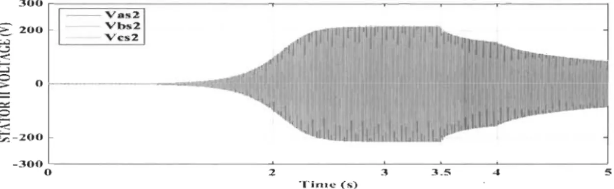
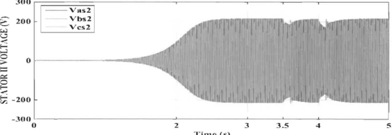
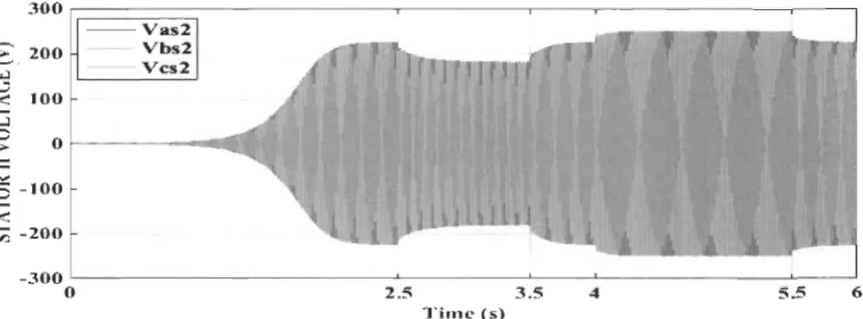
Figure 3-10 Stator II voltage evolution at no-Ioad ... 63
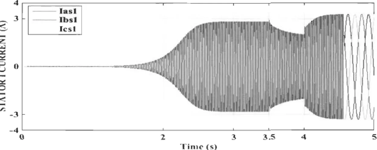
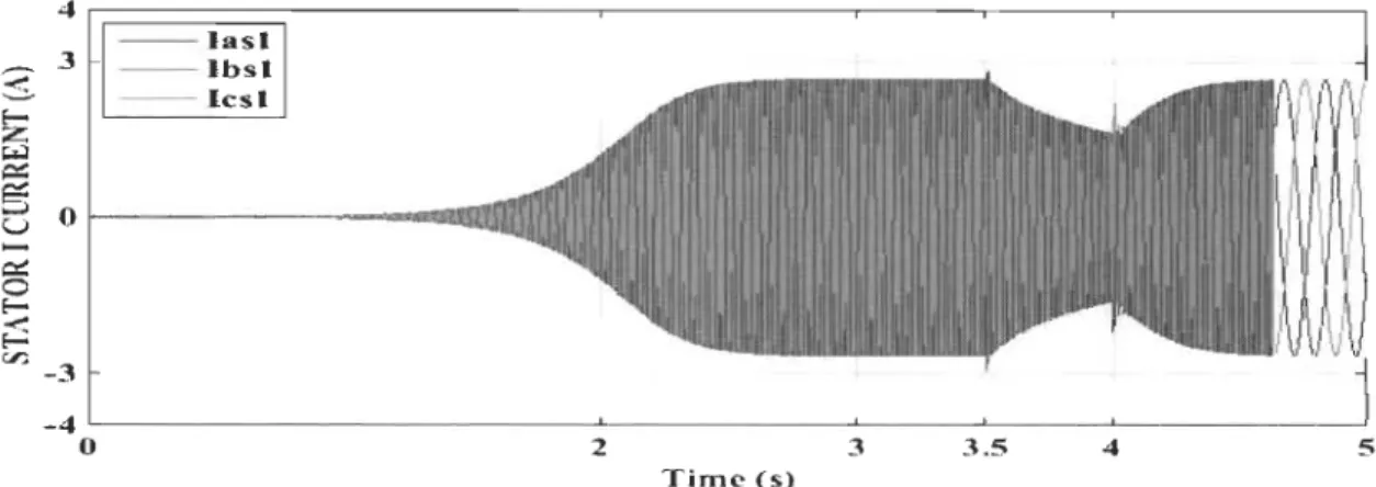
Figure 3-11 Stator 1 CUITent evolution at no-load ... 63
Figure 3-12 Stator II current evolution at no-Ioad ... 64
Figure 3-13 Phase shift between stator current and voltage ... 64
Figure 3-14 Rotor current evolution ... 64
Figure 3-15 Stator 1 voltage evolution in the presence of shunt PC ... 65
Figure 3-16 Stator Il voltage evolution in the presence of shunt PC ... 65
Figure 3-17 Stator 1 current evolution in the presence of shunt PC ... 66
Figure 3-18 Stator Il CUITent evolution in the presence of shunt PC ... 66
Figure 3-19 Stator 1 voltage evolution in the presence of series PC ... 67
Figure 3-20 Stator II voltage evolution in the presence of series PC ... 67
Figure 3-21 Stator 1 current evolution in the presence of series PC ... 68
Figure 3-22 Stator Il CUITent evolution in the presence of series PC ... 68
Figure 3-23 Stator 1 voltage evolution with step change in load without SSPC ... 69
Figure 3-24 Stator Il voltage evolution with step change in load without SSPC ... 69
Figure 3-25 Stator 1 current evolution with step change in load without SSPC ... 70
Figure 3-26 Stator II current evolution with step change in load without SSPC ... 70
Figure 3-27 Stator 1 voltage evolution with step change in load with SSPC. 70 Figure 3-28 Stator II voltage evolution with step change in load with SSPC71 Figure 3-29 Stator 1 current evolution with step change in load with SSPC .71 Figure 3-30 Stator II current evolution with step change in load with SSPC 7\ Figure 3-31 Rotor speed variation ... 72
Figure 3-32 Stator 1 voltage evo\ution with step change in speed with SSPC ... 72
XIX
Figure 3-33 Stator Il voltage evolution with step change in speed with
SSPC ... 73
Figure 3-34 Stator 1 current evolution with step change in speed with SSPC ... 73
Figure 3-35 Stator II current evolution with step change in speed with SSPC ... 73
Figure 4-1 D-STA TCOM connected to the grid ... 77
Figure 4-2 Three legs voltage Icurrent source converter ... 78
Figure 4-3 Configuration ofD-STATCOM ... 79
Figure 4-4 Phase Locked Loop ... 82
Figure 4-5 Bode diagram of the transfer function ... 84
Figure 4-6 Bode diagram of power system transfer function with variation of Lf ...... 85
Figure 4-7 Bode diagram of power system transfer function with variation of Rf ... 86
Figure 4-8 Phase margin variation with Lf ............. 86
Figure 4-9 Phase margin variation with Rf ......................... 87
Figure 4-10 Siiding mode control process ... 88
Figure 4-11 Cascade SMC ofD-STATCOM for power factor correction .... 90
Figure 4-12 Saturation function ... 93
Figure 4-13 DVR configuration ... 95
Figure 4-14 Phasor diagram ofDVR intervention ... 96
Figure 4-15 Hysteresis control of DVR ... 99
Figure 4-16 Grid voltage and current in the case of inductive load ... 100
Figure 4-17 Grid voltage and current in the case of capacitive load ... 101 Figure 4-18 Active and reactive power transfer between the grid and
0-STATCOM ... IOI Figure 4-19 D-STA TCOM output current in DQ frame ... 1 02
Figure 4-20 O-STA TCOM output CUITent in ABC frame ... 1 03 Figure 4-21 O-STA TCOM output voltage evolution ... 1 03 Figure 4-22 Grid voltage ... 103 Figure 4-23 OC-side voltage of D-STA TCOM ... 104 Figure 4-24 Voltage swell occurs in the grid ... 105 Figure 4-25 OVR intervention against voltage swell... ... 1 06 Figure 4-26 Load voltage after intervention against swells ... 106 Figure 4-27 Voltage sag occurs in the grid ... 106 Figure 4-28 OVR intervention against sag ... 1 07 Figure 4-29 Load voltage after intervention against sag ... 1 07 Figure 5-1 Topology of the U PQC in the proposed power system ... 112 Figure 5-2 Phasor diagram of the UPQC intervention (A): against voltage
sag, (B): against voltage swell, (C): against current
issues.[71] ... 114 Figure 5-3 Control algorithm applied on the series part of the UPQC ... 117 Figure 5-4 Positive sequence detector [141] ... 119 Figure 5-5 Block diagram of PLL circuit [141] ... 120 Figure 5-6 Control algorithm appl ied on the shunt part of the UPQC ... 122 Figure 5-7 Membership function [147] ... 123 Figure 5-8 Structure of the adaptive logic control[ 148]. ... 125 Figure 5-9 Oisturbed voltage source generator ... 126 Figure 5-10 (A): Grid Voltage, (B): Compensating voltage, (C): Load
terminaIs voltage (PCC) ... 127 Figure 5-11 Zoom of Figure 5-1 0 ... 128 Figure 5-12 Active and reactive power at load terminais ... 129 Figure 5-13 (A): Grid voltage (with harmonie generator), (B): Compensating
Figure 5-14 (A, B): Grid voltage and its harmonie speetrum (7th harmonie generator) (C, 0): Load terminaIs voltage and its harmonie
speetrum ... 131 . Figure 5-15 (A, B): Grid voltage and its harmonie speetrum (7th, 11 th
harmonie generator) (C, D): Load terminaIs voltage and its harmonie speetrum ... 131 Figure 5-16 (A): Load eurrent, (B): Compensating eurrent (C): Grid
eurrent. ... 132 Figure 5-17 (A, B): Load eurrent and its harmonie speetrum (C, D): Grid
cUITent, and its harmonie speetrum ... 132 Figure 5-18 Grid CUITent evolution with unbalaneed load ... 133 Figure 5-19 D-ST A TCOM output eurrent ... 134 Figure 5-20 Load and grid neutral eurrent evolution with D-STA TCOM
DC-side eurrent ... 134 Figure 5-21 Grid active and reaetive power. ... 135 Figure 5-22 Grid eurrent of phase A with and without D-ST A TCOM ... 136 Figure 5-23 Grid eurrent of phase B with and without D-ST A TCOM ... 136 Figure 5-24 Grid eurrent of phase C with and without D-ST A TCOM ... 137 Figure 6-1 System under study with MC-UPQC ... 142 Figure 6-2 LCL-filter bloc diagram ... 146 Figure 6-3 Frequeney response of LCL-filter with and without damping
resistor ... 147 Figure 6-4 Sliding mode control process ... 149 Figure 6-5 Saturation funetion ... 153 Figure 6-6 Control seheme applied on D-STA TCOM ... 154 Figure 6-7 Sine and eosine estimating bloek diagram ... 156 Figure 6-8 Control seheme applied DVR-I and DVR-II.. ... 157 Figure 6-9 SE-DSWIG output voltage ... 158 Figure 6-10 Voltage magnitude evolution ... 159
Figure 6-11 SE-DSWIG output current ... 159 Figure 6-12 SE-DSWIG output voltage in speed variation ... 160 Figure 6-13 Frequency profile in variable speed ... 160 Figure 6-14 Output voltage in variable speed ... 161 Figure 6-15 Compensating voltage generated by DVR-I and DVR-II ... 161 Figure 6-16 Stator II output voltage ... 162 Figure 6-17 Compensating voltage ... 162 Figure 6-18 Load terminal voltage ... 163 Figure 6-19 Grid voltage sag and swell ... 163 Figure 6-20 Grid frequency evolution following the voltage sag and swell164 Figure 6-21 Compensating voltage generated by MC-UPQC ... 164 Figure 6-22 Grid voltage magnitude ... 165 Figure 6-23 D-STA TCOM active and reactive power transferred with the
grid ... 165 Figure 6-24 Grid frequency at the presence of MC-UPQC ... 166 Figure 6-25 Grid current at the presence of MC-UPQC ... 166 Figure 6-26 Active and reactive power evolution during reactive power
injection ... 167 Figure 6-27 Active and reactive power evolution during reactive power
injection ... 168 Figure 6-28 Active and reactive power evolution during reactive power
absorption ... 168 Figure 6-29 Active and reactive power in reference tracking test ... 169
List of acronyms
AFLC Adaptive Fuzzy Logic Controller
CSP Concentrating Solar Power
CPD Customer Power Devices
CSC Current Source Converter
DFIG Double-Fed Induction Generator
DSWIM Dual Stator Winding Induction Motor
D-SATCOM Distributed Static Synchronous Compensator
DVR Dynamic Voltage Restorer
EPRI Electrical Power Research Institute
F ACTS Flexible AC Transmission System
GTO Gate Tum-Off
lG Induction Generator
IRENA International Renewable Energy Agency
LVRT Low Voltage Ride Through Capability
MC-UPQC Multi-Converter 8ased Unified Power Quality Conditioner
NPCs Neutral Point Clamped Converters
PAC Parallel Active Compensator
PC Passive Compensator
PCC Point Common Coupling
PLL Phase Locked Loop
PMSG Permanent Magnet Synchronous Generator
PQ Power QuaI ity
PV Photovoltaic
PWM Pulse- Width Modulation Technique
RE Renewable Energy
SAC Series Active Compensator
SEC Static Excitation Controller
xxv
SE-IG Self-Excitation Induction Generator
SMC Sliding Mode Control
SPAC Series-Parallel Active Compensator
SSPC Series-Shunt Passive Compensator
SE4ALL Sustainable Energy for Ali
UPQC Unified Power Quality Conditioner
VSC Voltage Source Converter
1. Motivation
1.1 A brier history on the energy
Since ancient times, the human being has been striving for the domination of natural resources to compensate his weakness in face of the daily challenges and to facilitate life. He had exploited the wind power to push ships in maritime transportation around the then known world [1]. As weil, thousands of years ago, people of China and Greek also discovered the benetit of solar energy. They built their hou ses and neighborhoods in a specifie position to absorb the sunlight during the day and reject the heat into homes especially during the winter nights. More than that, historians have reported that the Greek people with the help of Archimedes had used sunlight as mass destruction weapon against roman navy forces, in which they concentrated the sunlight on their ships to bum them using a polished metal as a mirror [2]. In the fourth century, the people in the Far-East explored the co al and extract power from it for heating, melting metals and foundry. In the eighteenth century, the coal has been used on a large scale particularly with the emergence of the industrial revolution in Europe. In the end of 1800s, the tirst coal-fired steam based DC-current dynamo for power generation was proposed by Siemens [3]. A few years later, Thomas Edison established the tirst power station where the generator was driven using coal-tired. Ali power stations implemented at that time characterized by a DC-current and low voltage generation, for that, the end user was installed near the source to reduce losses [4]. At the beginning ofthe 1900s,
2
scientists have designed new AC-current alternators, transformers, and with the exploration of new natural resources such as oil, gas and, nuclear, it became possible to transport power over long distance and interconnects power stations between them, which increases the installed capacity [4]. Meantime, the electric power generation area attracts attention when it proved its great impact on the economic development. Thus, huge sums have been invested to enlarge the transmission and distribution grids which help to raise the access to electricity. Furthermore, authorities have encouraged and supported research and development in this field with the introduction of new technologies enabling to build huge thermal and nuclear stations which attain 1000 MW by the end of the 1980s [5].
Despite that, 1.2 billion of the worldwide people do not access to electricity and 85% of them live in the countryside according to the World Bank's sustainable energy for aIl (SE4ALL) database [6]. Moreover, according to the Electrical Power Research Institute (EPRI), losses due to outage and power quality issues, only in the USA, cost between 119 $ and 188 $ billions a year [7]. Besides, environmental organizations around the world called the attention about the rapid depletion of fossil fuels and the attendant global warming issue related to the high exploitation of these conventional resources su ch as oil, gas, and coal. Accordingly, we draw that the conventional methods of the power supply based on the installed of huge power stations and the extension of the power transmission grid are not economically feasible and technically so difficult. For example, in Canada, there are 200 000 people located in 280 rural areas which are not connected to the utility grid and use high co st and fossil fuels for power supply [8]. Thus, it is necessary to proceed to explore other potentials for promoting the electricity access, especially in the remote region, with less capital investment and with considering the reduction of greenhouse emissions.
1.2 Renewable resources: Status and Trends
Renewable energy (RE) knows a fast expansion since the first United Nations framework convention on climate change in Rio de Janeiro [9]. As weil, in 1997, the Kyoto protocol has encouraged the worldwide nations to establish an energy policy by the exploitation of renewable resources [10]. More than this, the crisis of oil prices at the beginning of the new millennium, has boosted with a strong impulse researches towards safe and domestic alternative solutions. The renewable energy market provided more than 20% of the worldwide final energy consumption and has employed 9.8 million by the end of2016 [II]. Renewable energies come from the displacement of natural elements from a position to another one, such as photons from the sun, movement of wind, water in rivers. It also is delivered through the transfer of natural resources from astate to another, like the fungal fermentation of animal wastes to get a biogas. Consequently, RE depends mainly on the exploration of constantly replenished natural resources to get power, which makes it eligible to supply people in rural areas with low cost and even in off-grid operating mode. This thesis is dedicated only to wind power generation, but we presented a short description of the most popular sources for supplying c1ean and renewable energies.
1.2.1 Biomass energy
The term of biomass summarises mechanisms of transforming residuals, wood wastes, municipal wastewater and solid wastes, livestock, etc, into other forms, which will be used as energy, through several processes such as thermal, and biological. The biomass industry has sharply increased and extended in new areas of the world, especially for heating and cooling, where it hosts 9% of the total renewable energy used in this field [II]. Biomass is also used to generate electricity by producing steam to drive turbines through a direct
4
combustion offeedstocks or bio-fuel. As weil, the biomass gasification technique is used also to get hydrogen, methane and other gases used in several sectors[ 12]. Figure 1-1 recapitulates ail the biomass bath [13].
'---
....
::=-
...
~..
...-.
o
. . . l .. ~llIJtCilll-~-r-~---
.-.
...
"r- ... - ... · _ .... -e ... -. -. -. -. -. -. - -. -. -. _ _ ...J-o;.t~ 1 ,',1 ea-;. ,11 '_- .. ~t',
.-.~--""---.
"',-
-
,..
10 ... _ . . ....
_--~ ..Figure 1-1 Biomass path [13]
1.2.2 Geothermal energy
Mainly, the geothermal energy based on the extraction ofheat stored in the depths of the earth via various techniques such as dry steam power plants, flash power plant, binary cycle power plants, etc. [14]. To collect this energy, a fluid is injected into the interior of the earth where it collides with hot volcanic rocks, then returns to the surface carrying heat which will be used directly or exploited to generate electricity. In 2016, the global power generated using geothermal touched the edge of 12.7 GW, following the International Renewable Energy Agency (IRENA) affirmation [II].
1.2.3 Ocean energy
Ocean (marine) energy has a significant potential to share the burden ofproducing a c1ean and sustainable energy for the coastal communities. It contributes to the total energy production by 536 MW by the end of 20 16, while ocean energy stakeholders have pledged to raise the proportion to 300 GW by 2050 [15]. However, it is stillless-attractive compared to other renewable energies. ln commercial-like approach, it requires the investment of high upfront. ln 2001, the ocean energy has been installed in three countries, and then the number is increased to 25 countries in 2016, as shown in Figure 1-2. The extraction of power from ocean passes through numeroLls techniques, such as wave energy, tidal range, tidal currents and so on [16]. 2016 20U 201. 2D1l 2012 2011. 19 19 21 2010 2009
================================~
1718
200. tG 200' 12 2006 9 2005a
2004 7 2003 7 2002 5 2001 3Figure 1-2 Countries membership in ocean energy [15] 23
23
6
1.2.4 Hydropower energy
Hydropower is the electromagnetic conversion ofkinetic energy, captured from the water flow in rivers and damps, into an electric energy by using turbines. The hydropower stations vary from few kilowatts to hundreds of megawatts such as the biggest station in China by 22.44 G W [17]. ln 2016, the global world hydropower installed capacity was increased by 25 GW arriving to 1.096GW [11]. The world-wide hydropower capacity and generation state vary from a country to another. ln 2016, Canada has ranked the second in hydropower installed capacity after the China by 79 323 MW where it covers more than 97% of the Quebec total electricity needs [18].
1.2.5 So/ar energy
The solar energy is the use ofsunlight to produce electricity via photovoltaic (PY) system and concentrating solar power (CSP), or heating and cooling through thermal stations. PY-based energy depends on the conversion of sunl ight into a direct current using PY - modules, while CSP-based energy produces electricity by the same procedure of PY, which will be used for heating water or any liquid or gas to get steam to drive turbines. The solar thermal technique is deduced for heating or cooling industrial and domestic spaces. The solar energy market knows a fast growth in 2016, practically with the historic drooping in PY modules prices by a rate of29% to 0.41 $ per Watt [11].
1.2.6 Wind energy
Wind power bases on the conversion of wind energy into another sort of energy such as electricity. Nowadays, it becomes the most popular among renewable energies and a big contributor in the worldwide final power consumption by 487G W installed capacity in 2016
as illustrated in Figure 1-3. However, the penetration of wind energy in the total power consumption is relative from a country to another, for example, 45% in Denmark, without forgetting its historic date where the wind power production exceeds the country power
consumption on November 3rd 2013 [19]. 200
1
59
198
lOG Woridfotaf487 Œgawatts
433
o--~~~---~~~~~~~---Figure 1-3 Expansion ofwind energy [Il]
1.3 Main parts of wind turbine
The classification of wind turbines depends on the area where the y are implemented
(offshore, onshore), type of generator, power electronic devices used for the power
conversion. From a mechanical point of view, a wind turbine could be in a vertical or
horizontal position, depending on the state of axis carrying blades. The mechanical part
contains a rotor which is represented by the axis and blades, a gearbox, a tower and a
supporting basis. The electrical part comprises a generator, power electronic devices, and a
8
1.3.1 Power electronic devices in wind turbine
The first generation of wind turbines operates at fixed speed where the generator is
connected directly to the grid through a simple starter controlled by a thyristor as shown in
Figure 1-4 [21].
SOIG
Soft-starter
:
UJ
Capacftor
bank
Figure 1-4 Fixed speed based wind turbine [21]
However, this topology (Figure 1-4) is sensitive to the speed variation resulting in an
injection of harmonic into the grid [22]. By the emergence of semiconductors field, another
generation of power electronic devices has been revealed by the end of the 1980s. lt is
represented by one stage converters based rectifier or a chopper, used to control the rotor
resistance of a double-fed induction generator (Figure 1-5) that helps in damping the
influence ofwind speed fluctuations on the power quality [19]. With the beginning of the
new century, an advanced category ofmulti-stage, bidirectional converters have appeared. lt
enables the wind turbine to operate in full-scale variable speed, which improves its efficiency and increases the capture of power [23].
Variable
r
es
i
stanœ
WRIG
Soft-starter
capaclto
r
bank
Figure 1-5 Partial variable speed based wind turbine [21]
1.3.2 Generator in wind turbine
Several topologies have been proposed in fixed speed, partial-variable speed and variable speed conditions, basing on: wound-rotor synchronous generator (WR-SG), permanent magnet synchronous generator (PMSG), double-fed induction generator (DFlG) and self-excitation induction generator (SE-IG) [19].
1.3.2.1 Wound-rotor
synchronous generator
Basically, wound-rotor synchronous generator (WR-SG) has been widely used in a conventional steam-based power plant where it operates at high and constant speed. In the
10
start-up, the rotor ofWR-SG should be connected to a OC current source to get the necessary excitation [24]. Occasionally, WR-SG is also used as a dynamic voltage and reactive power compensator especially in the off-grid operation. ln wind power generation, WR-SG is connected through a full-scale back-to-back converter. The main drawback of WR-SG is the bulky volume and high cost i.e.; regular maintenance of collector rings and brushes is necessary since it needs an external source of excitation through the rotor [25].
1.3.2.2 Permanent synchronous generator
PMSG is more popular in wind energy application compared to WR-SG where it doesn't require an external excitation nor rings for the collection of reactive power. lt also induces less-noise since the absence of a gearbox. ft has been used in several applications such as HYDC, HV AC, low and medium voltage, using double stage back to back converters or three stages (AC-OC) -(OC-OC) -(OC-AC) based topologies [23]. The main disadvantage of PMSG is the risk of the demagnetization due to a peak in current or augmentation in temperature, and decrease in magnet effect over time [26].
1.3.2.3 Double fed induction generator
In the last few years, the DFIG dominates the industry of wind power. The first wind turbine based DFIG was operating in partial variable speed, in which the stator is directly linked to the gr id and the rotor is connected to an adjustable resistance [22]. This topology has improved the wind turbine efficiency and increased the captured power with the enhancement of its quality. The value of the resistance varies with the variation of wind speed. Thus, the higher the speed is the more the resistance is bulky the higher the power loss is. For that, the speed variation tolerance is limited in order to decrease the power extracted
by the rotor. Since the 2000s, a new topology based DFIG has been proposed, where the rotor
is also connected to the grid through a low size and cost back to back (BTB) converter. This
solution permits controlling both the frequency and the rotor characteristics, which enhances
the performance of the wind turbine in a wide interval of speed variation. Recently,
researchers have explored a new topology using an AC-AC matrix converter instead of the
BTB converter. This technique reduced the cost furthermore, where no dc side capacity or a
battery is required, and also it simplifies the control strategy in which it is applied only to
one converter. However, DFIG based topologies suffer from sorne disadvantage such partial
scale power capacity, need of a periodic maintenance of slip rings and gearbox, high cost,
high number of switches (18 switches in the matrix converter) which increases power loss,
sensibility against the grid faults and poor ride-through capability [27].
1.3.2.4 Self-excitation induction generator
The use of Induction generators (lG) on large-scale returns to 1980s, where it has been
used to build the Oanish concept wind turbines. In this topology, the IG operates at fixed
speed and is connected directly to the grid. While a fix-ratio gearbox is used to couple the IG
with the rotor of the turbine[22]. By the advance of power electronic, another topology was
proposed with the introduction of a full-scale BTB converter between the JG and grid. Such
feature offers the possibility to control the generated power and enlarges the controllability
of speed with a reduction in co st (no need of gearbox nor slip rings). Comparing to author
generators, absolutely IG is more advantageous for several reasons. It is characterized by a
small size machine, low-cost of operation and maintenance, brushless, high performance in
12
Nevertheless, this doesn't prevent the existence of sorne disadvantages, such as the weak control of voltage and frequency and needs of reactive power [25].
1.3.3 Goals and challenges ofWind turbine industry
Nowadays, the industry of wind turbines knows a fast progress, with a size turns around 7-8MW. The initiative targeted is to build 10-20 MW wind turbine and to reach an installed capacity cutting the edge of 800 GW by 2020 [19]. Several grid codes have been issued to manage the behavior of wind turbine. In which, even with the unpredictability of climate conditions and the fluctuation of wind speed, wind turbines should behave as a traditional power station in terms of power quality [29]. The wind turbine has to be also featured by the possibility to control the delivered active, reactive power and to offer support services for the utility grid characteristic, such as adjusting the frequency and enhancing the voltage profile, etc. [26]. ln addition to that, wind turbine manufacturers are invited to promote new techniques to increase the generated power capacity, reduce the cost of maintenance, improve low voltage ride through capability (LVRT). In this sense, one of the most promising solutions in this area is the use of multiphase generators where the number of phases is more or equal ta six. In the following, we present a survey on the multiphase generator, exactly a dual stator (six phases) induction generator.
1.3.4 Self-excitation dual stator winding induction generator: State-of-the-art on
multiphase generator
Due to the high economic yield and with the same reason for preferring multiphase instead of single phase systems for the transportation of power, a new generation of multiphase generators (phases number is more or equal to six) has been strongly emerging
especially with the expansion of power electronics field [30]. This category brings a many
advantages compared to the traditional three-phase generator. For example, since the number
of phases is increased by two-time, also the generated power will be doubled without
increasing the current per phase [31]. On the other hand, it also reduces harmonics, rotor
losses, and torque ri pp les [23]. Multiphase generator penetrates the wind power generation
field in grid-tied and stand-alone topologies. The additional degrees offreedom in multiphase
generator allows it to inherit the conventional three-phase generator (such as DFIG) in the
medium voltage operation (up to 8 MW), with more flexibility and high fault tolerance [32].
Among multiphase machines, self-excited dual stator winding induction generator
(SE-DSWIG) have been proposed in many applications [33]. It consists of two identical
three-phase winding sets which permit building several topologies [30]. Each three-phase winding
set forms a stator, where the first one is called in such papers control winding and the second
one is called power winding [34]. There is no physical contact between stators, that reduces
the propagation of harmonics between them and enhance the electromagnetic compatibility
in the power system [30].
ln previous works, researchers proposed topologies in which the control winding (stator
1) is connected to what they called, a static excitation controller (SEC), while the power
winding (stator II) used to feed the end user as shown in Figure 1-6. The control winding
with the SEC is used to compensate reactive power, to regulate voltage, enhance the
frequency and to maintain the excitation of the generator [35]. This topology was proposed
in standalone applications to meet the growing power request for the recent trend in wind
SEC SE-OSWIG
PCC
, ,
,
, ,
•
,
,
'
\...-_---Figure 1-6 First topology based SE-DSWIG
14
ln stand-alone applications, SE-DSWIG has been perfectly used in fixed and variable frequency ac systems, hydro and wind power extraction, as weIl as for simultaneous hybrid DC/AC output voltage supply. For instance, in [36], authors used SE-DSWIG in variable frequency AC application. The power winding set generates an AC power and the control winding set connected to the SEC. This later injects a variable reactive power into the machine to compensate the voltage dips and to stabilize frequency. At the same time, the SEC provides a DC voltage through its DC-bus supply. A control strategy based on the instantaneous slip frequency is applied to the SEC. Experimental results show good stability of voltage and frequency even with variation in load impedance. In [37], the power winding set feeds an unbalance load while the control winding through the SEC is used to regulate the positive sequence of the power winding set output voltage and current and to eliminate the negative sequences of the unbalanced load. In [35], authors used the same topology presented in Figure 1-7, where they tried to optimize the excitation capacitor with taking into account the generator parameters, prime mover speed, load variation, and the evolution of the wind turbine power curve. ln this case, the SE-DSWIG has been used also for dc voltage application where the SEC acts as a rectifier for charging batteries and feeding dc current
load. ln [38], Haijun Xue et al. made a comparison between four control strategies applied
on SE-DSWIG for DC power generation. These control strategies are control-winding flux
orientation control, control-winding voltage orientation control, control-winding direct
power control, and instantaneous slip frequency control. Ali the proposed control strategies
proved their capability in dc voltage generation with more superiority for the instantaneous
slip frequency control in terms of DC voltage stability. In [39], Feifei Bu et al. proposed an
asymmetrical analysis of the SE-DSWIG operating in variable frequency and feeding an
unbalanced load. Results show that the SE-DSWIG has a good behavior even in unbalanced
load scenario. The negative sequence and harmonic current generated by this fault don't
propagate between stators. In [40], Kamal Nounou et al. evaluate the performance of the
SE-DSWIG under variable speed and at different loads. A vector control strategy is built up and
applied to the system basing on the method of indirect rotor flux orientation control which
brought a good performance for the system. This work [41], presents a study on SE-DSWIG
performance for variable frequency AC generation, feeding a variable capacitive-inductive
load. The contribution of this work is established on the proposition of an improved
instantaneous slip frequency control strategy applied on the SEC with considering the active
and the reactive power consumed by loads. ln [42], authors investigate the use ofSE-DSWIG
to generate DC voltage with both of stators through two rectifiers, using a control technique
based on nonlinear input-output linearization. While in [43], Feifei Bu et al. proposed a
9-phase induction generator operates in very high-speed range. The power winding consists of
six phases forming a dual stator, used for the DC voltage generation through two rectifiers.
The DC-buses of both rectifiers are connected in shunt to maintain the DC voltage at an
SE-16
DSWIG performance and to charge the battery as depicted in Figure 1-7. The SEC IS controlled using the control-winding-tlux orientation control strategy.
Win.d
Turbine
IPower-Winding Sidel
*
Rectifiers
L(
Control-Winding Side
l
SECFigure 1-7 wide-speed rage operation of SE-DSWIG for OC power generation [43]
To meet the growing electrical power demand for automobiles in term of electric power steering, heated seats, electronic ignition, etc., which is consistent with the evolution of electric vehicles, Malakondaiah Naidu et al. in [44] suggested the adoption of a new 42V-4kw power system based SE-DSWIG, instead of the Lundell alternator. In this topology, the power winding feeds loads through voltage source inverter and the control winding charged the battery through a diode bridge rectifier. In [45], SE-DSWIG has been used also in AC and DC-microgrid applications. The control winding is connected to a voltage source converter, forming DC-microgrid, while the power winding supplies load through AC-DC-AC converter forming an AC-DC-AC-microgrid (Figure 1-8). The proposed topology shows a good
performance in term ofpower quality in both AC and DC-microgrid.ln [46], Saptarshi Basak et al. dealt with the improvement of power quality and mitigation of voltage disturbance. For that, they used passive compensators based on inductance and capacitance, inserted in series and shunt between the dual stators and inverters. However, details regarding the design of the passive compensators are missing.
Battcry StorRge
PC
Figure 1-8 Topology proposed for microgrid operation [45]
In [47], O.K. Singh et al. made an in-depth study on the steady-state performance of SE-DSWIO in a standalone application. The SE-SE-DSWIO is presented in simple shunt, short shunt, and long shunt configurations. The models are developed using the nodal admittance based graph theory, while the obtained matrix equations are solved using a genetic algorithm. Authors identified the parameters of the generator under study, as weil as the values of the excitation capacitance in different configurations and under load and no-load conditions. ln [30], a passive compensator based capacitance has been employed to improve the power
18
quality of a SE-DSWIG in standalone application. The proposed passive compensator shows
a high efficiency against voltage sag and swell. In [34], the performance of SE-DSWIG in
grid-tied function was investigated (Figure 1-9). Authors attempted to control the evolution of reactive power between the power winding and the grid in several fault scenarios emulated by a step variation. The SEC is connected to the control winding and supervised by the model
reference adaptive control strategy. The proposed topology with the control technique enhanced the dynamic performance and the stability of the power system.
Grid
Figure 1-9 Topology proposed to improve the reactive power controllability [34]
lt's remarkable that only a few attempts have been dealt with SE-DSWIG performance in
variable speed applications such as in wind power generation. ln [48], H. Amimeur et al.
proposed a system of wind energy conversion based on SE-DSWIG. They used the MPPT technique to optimize the power for speed range under the nominal and to limit the power
the grid through an AC-OC-AC converter. The dual stators are used as a power winding
(supplying power) and both are connected to a controlled rectifier. Both rectifiers are
attached between them in DC-sides to maximise the power supplied, then connected to the
grid through a single controlled inverter as shown in Figure 1-10. The SE-DSWIG is
controlled using field oriented control strategy associated with sliding mode technique. The
grid side converter is piloted using a c\assical feedback based PI controller. In [49], Samira
Chekkal et al. proposed the same topology used in [48], however, a fuzzy logic control
technique is used to control the torque instead of the MPPT technique to optimise the power
of the conversion chain. This technique doesn't require any characteristics of the turbine or
any exact mathematical model ofthe system.
lusl Vasl :
-t--+-~a---; ....
INVERTERI
INVERlER 2
20
ln [50], Fatima AMEUR et al. also used the same topology explored in [48], but they
applied direct power and flux control on the SE-DSWIG to improve the response of the power
system. Tu grid or
ne
upply Grid Bidirectional VI' f Ic
....
n! 2' f 2 Control "-'''\ \Vindîng1
(
·W). Pl ~!
1 j /" \. ... ,...~~ ... ""~ ... h~~ ... 4 .. ~ ... " • • ~.~ ... · · · / Power Wimling (P\ ,PIFigure 1-11 Topology proposed in [51]
Wind turbine
In [51], authors investigated the act of SE-DSWIG in variable speed applications (Figure
1-11). The generator is connected directly to the grid through the power winding (PW), and
a SEC is attached with the control winding (CW) side. The control winding pole number is
three time the power winding pole number. This feature eliminates the electromagnetic
interaction between stators and minimises furthermore the torque ripples in transient
response. In [52], Feifei Bu et al. discussed the possibility to use SE-DSWIG for hybrid AC
and DC microgrid application. The proposed topology consists of a power winding connected
of the AC grid, while the control winding is connected to a SEC and used to maintain the generator excitation and feeds OC loads.
Il)brid AC&iOC .. kro-crid Crid
- j
lE
1
J
CT
•
SEC1
Figure 1-12 SE-DSWIG for hybrid AC & OC power generation topology [52]
In view of ail papers that have been cited above, we conclude that the SE-DSWIG is a promising technology for stand al one and grid-connected applications. It shows a high efficiency for variable frequency applications in aerospace, maritime, vehicles and for extraction of hydropower. In variable speed application, SE-DSWIG was driven with a sufficient speed in which it varies around the nominal speed. The MPPT technique is used to optimize the power at low speed and to limit it at high speed, that means remains power within acceptable nominal limits. While AC-OC-AC converter is used to synchronize the generator on the same frequency of the grid. Nevertheless, the proposed topologies, especially in variable speed operation, had a weak ability to deal with sudden and large speed variations, which induce voltage collapse and disturb the frequency. Hence, it's imperative
22
to improve the low voltage ride through capability ofSE-DSWIG and maintaining the power
flow at an adequate level even during wind speed variation or mains voltage sags.
1.4 Research Goals
In the literature, the power conversion systems based on SE-DSWIG are used in
traditional topologies where the generator is connected to the grid through back-to-back
converters. ln addition to that, we did not find a strong study about the ability of maintaining
the proposed topologies connected to the grid even at the presence of issues in terms of
voltage sag and swell. Hence, the target of this thesis is to propose a new concept of power
improvement in wind turbine based SE-DSWIG. The orientation ofthis thesis is twofold: the
first one is the use of a dual stator induction generator to increase the generated power by
two-time compared to a convention three-phase induction generator, and the second is to
propose a new technique for the power quality improvement of a wind turbine in any
scenario.
1.4.1 Main objective
The main objective ofthis thesis is highlighted as follows:
• 8ased on the literature, a depth investigation on SE-DSWIG and its advantages
compared to the conventional three-phase induction machine was proposed.
• Exploration of a six-phase induction motor for a drive application.
• Design of a passive compensator based inductance and capacitance to ameliorate the
• Investigation on customer power devices (D-ST A TCOM, DVR, UPQC) and their
capability to improve the power quality in a wind turbine based SE-DSWIG.
• Design and insertion ofpassive damping LCL filter between customer power devices
and the grid, to elimination the penetration of harmonic.
• Low voltage ride through enhancement for the proposed wind turbine based
SE-DSWIG
• Development of nonlinear and adaptive based sliding mode and fuzzy logic control
strategies respectively, to ensure a smooth functioning of the multi-variable system
(SE-DSWIG, UPQC).
1.4.2 Contribution ofthis thesis
• This work proposes a new topology of wind energy conversion systems based
SE-DSWIG for grid-connected and standalone applications in the same time. SE-DSWIG is
connected to the grid through the first stator and supplying an islanded microgrid through the second stator winding.
• Multi-converter based unified power quality conditioner (MC-UPQc) is connected
between the grid/load and the generator to compensate the supply voltage imperfection,
enhance voltage and current at the PCC even in the presence of sudden faults, ameliorate the LVRT capability, and synchronize the generator on the same frequency of the grid.
• The proposed MC-UPQC involves three converters connected back to back through
an energy storage system, which permits exchanging active power between them.
• Two converters of MC-UPQC are acting as DVR where each one of them is
24
converter behaves as a D-STA TCOM and connected in shunt between the grid and the first stator through a passive damping LCL filter.
• Following the challenges entrusted by the MC-UPQC, a cascade sliding mode control
technique is applied on D-STATCOM whereas a synchronous reference frame control theory
is used to supervise both DVRs.
1.4.3 Publications
F. Hamoud, M. L. Doumbia, and A. Cheriti, "Performance Study of a Self-Excitation Dual
Stator Winding Induction Generator for Renewable Distributed Generation Systems,"
Smart Grid and Renewable Energy, vol. 7, p. 197, 2016.
F. Hamoud, M. L. Doumbia, and A. Cheriti, "Hybrid PI-Sliding Mode Control of a voltage
source converter based STATCOM," in 2014 16th International Power Electronics
and Motion Control Conference and Exposition, 2014, pp. 661-666.
F. Hamoud, M. L. Doumbia, and A. Ch, "Power factor improvement in WECS using cascade
PI control of passive damping LCL-filter," in 2015 International Conference on Sustainable Mobility Applications, Renewables and Technology (SMART), 2015, pp.
1-7.
F. Hamoud, M. L. Doumbia, A. Chériti, and H. Teiar, "Power factor improvement using
adaptive fuzzy logic control based D-STATCOM," in Ecological Vehicles and
Renewable Energies (EVER), 2017 Twelfth International Conference on, 2017, pp. 1-6.
F. Hamoud, M. L. Doumbia, and A. Chériti, "Voltage sag and swell mitigation using
D-STATCOM in renewable energy based distributed generation systems," in Ecological
Vehicles and Renewable Energies (EVER), 2017 Twelfth International Conference
on, 2017, pp. 1-6.
F. Hamoud, M. L. Doumbia, and A. Chériti, " Adaptive Fuzzy Logic Control Strategy to
Improve the Power Quality Using UPQC-S," in Energies, 2018 (submitted)
1.4.4 Outline ofthesis
The structure ofthis work is organized into seven chapters. The first one is devoted to an
introduction, contains a survey on renewable energies, different topologies of wind
energy-based generators and a state of the art of self-excitation dual stator induction generator.
The six-phase induction motor is fed with two inverters and is controlled using field oriented control with the indirect speed regulation method. The third chapter examines the behavior of SE-DSWIG that operates in a standalone application, with variable load and speed. A passive compensator is designed and used to mitigate issues in terms ofvoltage sag and swell. Chapter four presents a study on customer power devices (active compensator) based series and shunt compensators. Furthermore, it contains the step-by-step design method of passive damping LCL which will be used to eliminate switching ripples. Chapter five inspects another category more advanced of active compensator called unified power quality conditioner (UPQC). Chapter six is assessed the performance of the entire system proposed in this thesis. Finally, the general conclusion and the perspectives ofthis dissertation will be in the seventh chapter.
Chaptre 2 -
F
ield oriented control of a dual stator
winding induction motor with indirect
speed regulation method
2.1 Introduction
Primarily, the idea of a multiphase machine was supported by the revolution of variable
speed drive in high power application [53]. This attempt was boosted by several advantages
coming from the augmentation of phase number (more than three). The multiphase feature
of the machine gives high torque density with low pulsation and minimum harmonics [33].
Moreover, the power supply in drive application is segmented between two inverters that mean more degrees of freedom which implies high fault tolerance and more reliability
[54-56]. The most important property of multiphase induction machine is the elimination of the
space harmonics [57, 58]. These types ofharmonics are the most dangerous issues that could
bring malfunctioning to the counterpart three-phase induction machine. Space harmonics
come from the disproportionate distribution of the magnetomotive force (FMM) in the air
gap between the rotor and the stator [59, 60]. However, for a six-phase induction motor, the
space harmonics are eliminated which brings more stability and reduces vibration [32, 54,
59]. Such advantages encourage industrial companies to use this technology in several
motoring applications, e.g. the new generation of aircraft, propulsion, electric vehicles,
locomotive traction [32]. In this sense, we can cite the Hyundai ultra high-speed elevator
with nine phases, 1.1 MW motor [60], six-phase permanent machine for pumping oil [61],
The aim ofthis chapter is to apply a vector control based field orientation technique on a
dual stator winding induction motor (DSWIM). A description and mathematical modeling of
DSWIM are presented. After that, we evaluate the performance ofDSWIM in direct-fed from
the grid, then we use two inverters controlled in open loop using the pulse-width modulation technique (PWM). Finally, the vector control technique is applied.
2.2 Description of the dual stator winding induction motor
Figure 2-1 illustrates the DSWIM scheme. It contains a dual three-winding sets. The first three winding set is referred (al' a2J a3) and noted as stator l, while the second three-winding set is denoted (fh, f32J f33) and called stator Il. Every three-winding set of the stator is spatially shifted against the other by (J = 30°. Three phase-winding set called (ri' r2J r3) forms a squirrel cage rotor and displaced compared to the first and second stator winding sets by angle (Ji and (J2 respectively. The topology of the six-phase induction machine prevents the
propagation of any perturbation between the dual three windings, since the separation of the neutral point of both sets.
2.3 Mathematical modeling of DSWIM in biphase system
The modeling ofDSWIM in biphase system involves the transformation ofits equations from ABC frame to a DQ frame through Park crossing matrices given by [64]:
r
cos( a) 21l 21l cos( 8 - - ) cos( 8+
3') [p(a)]~
~
-Si~(a)
3 _ sin(8 _ 21l) _ sin(8+
21l) (2-1) 3 3 1 1.f'i .f'i .f'i
The mathematical modeling of the DSWIM in ABC frame is given in the electric and
28
Figure 2-1 Scheme ofDSWIM
2.3.1 Electric equations (2-2) (2-3) (2-4) (2-5) (2-6) (2-7) 2.3.2 Magnetic equations
(2-8) (2-9) (2-10) (2-11 ) (2-12) (2-13)
2.3.3 Power consumption and electromagnetic torque of DSWIM
The absorbed power by the DSWIM is given by the expression (2-14).
(2-14 )
Substituting voltages in (2-14) by their equivalents (2-2) -(2-7) it gives
PA
=
A+
B+
C (2-15)With:
(2-16)
(2-17)
(2-18)
The absorbed power involves the power losses (2-16), following the loule's heating
phenomenon, the variation of electromagnetic energy (reserve energy) (2-17) and
![Figure 1-7 wide-speed rage operation of SE-DSWIG for OC power generation [43]](https://thumb-eu.123doks.com/thumbv2/123doknet/14612914.732675/43.918.184.810.211.594/figure-wide-speed-rage-operation-dswig-power-generation.webp)
![Figure 1-10 SE-DSWING connected to the grid via back-to-back converter [48]](https://thumb-eu.123doks.com/thumbv2/123doknet/14612914.732675/46.918.187.802.530.911/figure-se-dswing-connected-grid-converter.webp)
![Figure 1-12 SE-DSWIG for hybrid AC & OC power generation topology [52]](https://thumb-eu.123doks.com/thumbv2/123doknet/14612914.732675/48.918.179.803.209.595/figure-se-dswig-hybrid-ac-power-generation-topology.webp)