HAL Id: tel-02096918
https://tel.archives-ouvertes.fr/tel-02096918
Submitted on 11 Apr 2019
HAL is a multi-disciplinary open access archive for the deposit and dissemination of sci-entific research documents, whether they are pub-lished or not. The documents may come from teaching and research institutions in France or abroad, or from public or private research centers.
L’archive ouverte pluridisciplinaire HAL, est destinée au dépôt et à la diffusion de documents scientifiques de niveau recherche, publiés ou non, émanant des établissements d’enseignement et de recherche français ou étrangers, des laboratoires publics ou privés.
Experimental Investigation and Discrete Element
Modelling
Ran Zhu
To cite this version:
Ran Zhu. Scale and Aggregate Size Effects on Concrete Fracture : Experimental Investigation and Discrete Element Modelling. Civil Engineering. École centrale de Nantes, 2018. English. �NNT : 2018ECDN0063�. �tel-02096918�
T
HESE DE DOCTORAT DE
L'ÉCOLE CENTRALE DE NANTES
COMUE UNIVERSITE BRETAGNE LOIRE
ECOLE DOCTORALE N° 602 Sciences pour l'Ingénieur Spécialité : Génie Civil
Par
Ran ZHU
Scale and Aggregate Size Effects on Concrete Fracture :
Experimental Investigation and Discrete Element Modelling
Thèse présentée et soutenue à l’Ecole Centrale de Nantes, le 20 décembre 2018
Unité de recherche : Institut de Recherche en Génie Civil et Mécanique (GeM)-UMR CNRS 6183
Rapporteurs avant soutenance : Composition du Jury :
Mohammed MATALLAH
Professeur, Université Aboubekr Belkaid Tlemcen Stéphane MOREL
Professeur, Université de Bordeaux 1
David GRÉGOIRE (président du jury)
Professeur, Université de Pau et des Pays de l'Adour Mohammed MATALLAH
Professeur, Université Aboubekr Belkaid Tlemcen Stéphane MOREL
Professeur, Université de Bordeaux 1
Cécile OLIVER-LEBLOND
Maître de conférences, Ecole Normale Supérieure Paris-Saclay François BIGNONNET
Maître de conférences, Université de Nantes Directeur de thèse
Ahmed LOUKILI
Professeur, Ecole Centrale de Nantes Co-encadrant de thèse
Syed Yasir ALAM
Acknowledgments
First of all, I would like to thank my supervisor professor Ahmed Loukili, for giving me the chance to study in France, and for his availability, his advice and his supervision throughout this work. Then, a big thank you to my co-advisor of thesis Syed-yasir Alam, lecturer at the ECN, for having accompanied me during about three years, for the many discussions and reflections, and for his patience and the time he has created, especially at the end of this work. Thanks to them, these three years of research have been extremely enriching for me.
My gratitude goes also to the technicians of laboratory: Vincent Wysnieski, Mathias Marcel and Eric Manceau for their professionalism and their daily help. Thanks to Katia Cushion for her patience and kindness.
Thank you to Abderrahmane Rhardane for guiding me, helping and encouraging me during these past three years!
I appreciate the colleagues of MEO group for their support and especially for their patience in teaching me the French language.
I would also like to thank my Chinese friends who supported and encouraged me during these three years at the ECN.
Abstract
It is now commonly understood that in the design of civil engineering structures, size effect must be taken into consideration. For concrete, this problem is complex because it does not exhibit plastic softening. The failure of concrete is generally preceded by propagation of cracks, characterized by a large microcracking zone (fracture process zone or FPZ) which is proportional to the maximum aggregate size (dmax). This fracture process is accompanied by strain-softening in the form of microcracking and fractional slip.
Experimentally, size effect in concrete is commonly studied by using geometrically similar notched beams where the nominal strength (N) obtained from the bending failure load is related to the characteristic dimension (D). This leads to a decrease in the ratio of dmax D with an increase in
the size of the structure. One of the objective of this thesis is to study experimentally the effect of heterogeneity (dmax D ) size. This ratio is recognized as a fundamental factor causing the size effect.
Three aggregate grading segments were tested on three different sizes of beams and the cracking process was investigated by acoustic emission and the image correlation technique. These methods make it possible to trace the crack openings and identify distinctively the FPZ.
The results demonstrate a significant influence of the aggregate size on the fracture behaviour of concrete. There is a direct relationship between the size effect parameters obtained by Bazant's law and maximum aggregate size (dmax). The results obtained from the specimen having the same size but made of concretes with different aggregate sizes produced the same classical size effect with identical transitional between LEFM and strength based laws.
The mechanical behaviour is modelled by the Discrete Element Method (DEM). However, the linear contact model inserted in DEM is not suitable to satisfy the materials like mortar and concrete with high unconfined compressive strength to tensile strength ratio. As a result, the model is modified to take into account the contribution of interparticle moments. The micromechanical parameters are determined by conventional tests with inverse analysis using the Levenberg-Marquardt algorithm. The results showed that this approach is able to reproduce the local cracking behaviour of concrete as well as classical size effect and aggregate size effect. Then, a softening model is developed to better reproduce the post-peak response and the cracking process.
Keywords : concrete, size effect, aggregate size, cracking, acoustic emission, digital image
Résumé
Il est de plus en plus admis que l’effet d’échelle doit être pris en compte dans la conception des structures de Génie Civil. Pour le béton, ce problème est complexe car celui-ci ne possède pas d’adoucissement plastique, et sa rupture est due à la fissuration caractérisée par une grande zone de microfissuration (fracture process zone) qui dépend de la taille du granulat dmax. Cette fissuration
passe par un adoucissement sous la forme de microfissures et de glissement interparticules.
Expérimentalement, l’effet d’échelle sur le béton est très souvent étudié à l’aide des corps d’épreuves homothétiques entaillés où l’on cherche à relier la résistance nominale (N) estimée à partir de la charge de rupture en flexion à une dimension caractéristique D. Ceci conduit à une
diminution du ratio dmax D avec l’augmentation de la taille de la structure. Parmi les objectifs de
cette thèse est d’étudier expérimentalement l’impact de l’hétérogénéité (dmax D ) supposé comme
facteur fondamental de l’effet d’échelle. Trois coupures granulaires ont été testées sur trois tailles de poutres différentes en suivant le processus de fissuration par émission acoustique et la technique de corrélation d’images. Celles-ci permettent de suivre l’ouverture des fissures et identifient assez clairement la FPZ.
Les résultats mettent en évidence une grande influence de la taille du granulat sur le comportement à la rupture du béton. Il existe une relation directe entre les paramètres de l’effet d’échelle obtenus par la loi de Bazant et la taille du granulat (dmax). Le traitement des résultats d’une
même taille avec différents granulométries dans le même diagramme conduit à la même loi d’effet d’échelle structurelle classique avec une valeur de transition identique.
La modélisation du comportement mécanique est effectuée par la méthode d’éléments discrets (DEM). Le modèle de contact linéaire ne s’avère pas adéquat pour le mortier et le béton où le rapport compression / traction est très élevé. De ce fait, Il a été modifié pour prendre en compte la contribution des moments inter-granulaires. Les paramètres micromécaniques sont déterminés par des essais classiques avec une analyse inverse en utilisant l’algorithme de Levenberg-Marquardt. Les résultats montrent que cette approche est capable de reproduire le comportement à la fissuration locale du béton et de reproduire l’effet d’échelle et celui des granulats. Ensuite, un modèle d'adoucissement est développé afin de mieux reproduire la réponse post pic et le processus de fissuration.
Mots-clés : béton, effet d’échelle, taille de granulat, fissuration, émission acoustique, corrélation
Table of Contents
I
Table of Contents
General Introduction ... 1
The scope of the thesis ... 2
Outline of the thesis ... 3
Chapter 1. Literature Review of Theoretical Models and Numerical Modelling of Concrete ... 5
1.1 Introduction to the fracture process in concrete ... 6
1.1.1 Fracture process zone: observation and characterization ... 7
1.1.2 Impact of ITZ on fracture behaviour ... 9
1.2 Theoretical models for quasi-brittle fracture in concrete ... 10
1.2.1 Cohesive Zone Model ... 10
1.2.2 Crack Band Model ... 11
1.2.3 Equivalent Elastic Crack Model ... 13
1.2.4 Damage Models ... 14
1.3 Numerical modelling methods for concrete ... 14
1.3.1 Continuum Approach ... 15
1.3.2 Discontinuum Approach ... 16
1.4 Numerical method used in the thesis ... 17
1.5 Summary ... 18
Chapter 2. A Comprehensive Approach for Numerical Modelling of Concrete by Discrete Element Method ... 19
2.1 Brief history of the development of Discrete Element Method ... 20
2.2 State of the art on Discrete Element Method... 20
2.3 Theory of Discrete Element Method ... 24
2.4 Contact model in the Discrete Element Method ... 28
2.4.1 Stiffness Model ... 28
2.4.2 Slip Model ... 29
2.4.3 Bond Model ... 30
2.5 Stress measurement ... 32
2.6 Strain rate measurement ... 33
2.7 Parallel bond model for the behaviour of the cementitious material ... 34
2.8 Modified Parallel Bond Model ... 38
2.8.1 Description of contact model ... 38
2.8.2 Validation of new contact model ... 39
2.8.3 Application to concrete: microstructure description and mechanical behaviour ... 40
2.9 Summary ... 45
Chapter 3. Experimental Investigation and Discrete Element Modelling of Concrete Fracture through Size Effect ... 47
3.1 Size effect in concrete ... 48
3.1.1 Review of size effect theories ... 48
3.1.2 Literature review of size effect in concrete ... 49
3.2.1 Material ... 52
3.2.2 Specimen preparation and testing procedure ... 53
3.3 Methods to analyse the fracture of concrete ... 55
3.3.1 Acoustic emission ... 55
3.3.2 Digital image correlation ... 62
3.3.3 AE and DIC investigation ... 65
3.4 Discussion and experimental exhibition of size effect ... 70
3.5 Numerical modelling for size effect using Discrete Element Method ... 75
3.5.1 Calibration of microparamters for mortar phase ... 75
3.5.2 Effect of 2D and 3D ... 77
3.5.3 Microparameters for concrete: ITZ and aggregate phases ... 79
3.5.4 Numerical modelling of size effect ... 83
3.6 Summary ... 85
Chapter 4. A New Approach to Size Effect by Scaling Microstructure ... 87
4.1 Introduction ... 88
4.2 Review of the aggregate size effect on the hardened concrete properties ... 88
4.2.1 Effect on tensile strength ... 88
4.2.2 Effect on flexural strength... 90
4.2.3 Effect on fracture characteristics ... 91
4.2.4 The role of aggregate size in classical size effect analysis ... 93
4.3 A new approach to study aggregate size effect on the mechanical behaviour of concrete: An experimental study ... 94
4.3.1 Effect of aggregate scaling on Brazilian strength ... 95
4.3.2 Aggregate size effect on flexural behaviour: transition from strength-based laws to LEFM ... 96
4.3.3 The relationship between aggregate size effect and classical size effect ... 98
4.3.4 AE and DIC investigation ... 100
4.4 Modelling for aggregate effect ... 102
4.5 Local behaviours of concrete ... 103
4.6 Summary ... 106
Chapter 5. A Displacement Softening Model for DEM and its Application ... 109
5.1 Development of local softening bond model ... 110
5.1.1 Yield surface ... 110
5.1.2 Model formulation ... 113
5.1.3 Model behaviour ... 115
5.2 Parametric study ... 117
5.2.1 Effect of friction coefficient ... 118
5.2.2 Effect of normal and shear strength ... 119
5.2.3 Effect of normal and shear stiffness ... 119
5.2.4 Effect of softening parameters ... 120
5.3 Model validation at local and macroscopic scale ... 121
5.4 Application to concrete: study of aggregate grain size effect ... 124
5.5 Summary ... 127
Conclusions and Perspectives ... 129
Conclusions ... 129
Table of Contents
III
Appendixes ... 133
A. The grading curves for sand and aggregates ... 133
B. The regression curves ... 135
General Introduction
1
General Introduction
Due to the wide range of sources of concrete materials, low prices, a simple construction process, pourability and adaptability to various environments, the concrete structure has occupied an increasingly important position in civil engineering and hydraulic structural engineering. With the development of materials science, the increase in structural span and height, and the diversification of structural forms, the size of concrete structures is increasing (such as large-span bridges, super high-rise buildings, water conservancy dams, seaport projects, etc.). Additional requirements have been put forward in the design and construction of today's projects.
Strength as an important performance indicator of concrete, it is very important to reflect the actual strength of concrete. However, due to the heterogeneous and quasi-brittleness of concrete, its strength is not constant, but it will change regularly with the change of size. This represents an intrinsic property of quasi-brittle materials and this phenomenon is called size effect. Size effect can be traced to the 15th century. Researchers in diverse fields have done a lot of research on it. Since the mechanical properties of concrete are linked to the size of the specimen, the difference in the mechanical properties of different concrete specimens cannot be accurately described without studying the size effect phenomenon. In the civil engineering, hydraulic engineering, and other subjects, the actual structural size is relatively large, it is difficult to carry out systematic experiments on the actual structure, only small-scale specimen simulation can be carried out in the laboratory. Therefore, whether the experimental results obtained from the laboratory have to guide significance and practicality of the actual structure has become one of the problems faced by researchers. The research on size effect is mainly to study the scale effect phenomenon of concrete mechanical parameters and the relationship between various parameters. This study is helpful to establish the relationship between concrete mechanical behaviour and concrete mechanical properties and explain the intrinsic link between concrete composition and structural properties. In addition, the study of the size effect of concrete contributes to the development of the discipline of concrete fracture mechanics. However, concrete is a composite of aggregate, mortar matrix and the interface between aggregate and mortar, and its fracture problem is much more complicated than ideal brittle materials. Before loading, micro-cavities and micro-cracks existed inside the concrete material. During the loading process, the micro-cracks are continuously generated, expanded and penetrated, and developed into macro-micro-cracks, which eventually resulted in the fracture of the concrete members. In addition, the development of cracks in concrete is not the development of a single crack, it has many cracks developing at the same time, and the crack propagation path is extremely tortuous and the crack surface is also rough.The fracture of the concrete structure may be the fracture of the mortar matrix or the fracture of the aggregate, or the failure of the bond interface between the mortar and the aggregate, and possibly the overall fracture caused by the combination of these fractures. According to the microstructure analysis of concrete, the failure of concrete is actually a complex structural change process. Therefore, the research on the performance of concrete structure should start from its mesostructure, focus on the characteristics of the non-uniformity of concrete materials, and explore deeply the failure mechanism of concrete damage and fracture according to its mesostructure and meso-mechanical properties.
The scope of the thesis
Size effect has been rigorously analysed by previous researchers. When a concrete structure is loaded, the strain energy is absorbed in the FPZ due to toughening mechanisms. As the structure size increases, FPZ becomes negligible, whereas, for small size structures, the FPZ can be of the same magnitude as the structure size. Thus, the presence of FPZ is considered the main cause of the size effect. Bažant [1] considered the size of FPZ as a material property and multiple of maximum aggregate size (dmax). Generally, as an inert filler, aggregate accounts for 60 % - 80 % of the volume
and 70 % - 85 % of the weight of concrete [1], of which, coarse aggregate occupies about 45 % of the volume of concrete [2]. Thus, the properties of coarse aggregate seem to have a significant effect on the performance of concrete. Coarse aggregate properties, such as grading, surface area, particle size and shape, angularity, surface texture, mineralogy, water absorption, and strength have been investigated [3-7].
Thus, it can be deduced that ratio between the structure size and the aggregate size is a fundamental factor which is causing the size effect. When the structure size increases, D dmax, the
ratio between the characteristic structural dimension D and the maximum aggregate size dmax
increases and approaches D, the material behaviour approaches linear elastic fracture mechanics
(LEFM). However, when the structure size is small i.e. at laboratory scale where D and dmaxare of
the same magnitude, LEFM is no more applicable. In this case mesoscopic and lattice element type finite element modelling is more predictive where aggregate size and distribution are explicitly taken into account.
The objective of this thesis is to investigate experimentally and numerically the role of the ratio max
D d as the cause of the size effect. This can be done by two methods: Method 1 by scaling D,
or Method 2 by scaling dmax. In the thesis, the two methods are investigated by using three types of
concrete mix ( 05C , 10C , and C20 ) which are designed with the same aggregate to mortar volumetric ratio and the same mortar properties. Only the aggregate sizes are changed. Aggregate sizes are up-scaled in 05C , 10C , and C20 concretes such that the volumetric fraction of each aggregate (i.e. d i da
( )
max) in each concrete remains same.− In the first series 1S , notched beam specimens are prepared using 10C (medium size
aggregate) and C20 (large size aggregate) concrete on geometrically increasing sized specimens ( D1 , D2 , D3 ). Besides, C05 (small size aggregate) concrete on geometrically increasing sized specimens (D1, D2) also investigated in the experiments.
In this way, the ratio D dmax is up-scaled (Method 1).
− In the second series 2S , three notched beams are prepared with the same dimensions
(specimen height, D1 and D2 ), each with different concretes C05 , 10C , and C20 respectively. In this way, the ratio D dmax is up-scaled in each beam (Method 2).
The beams are tested in three-point bending. Fracture process is monitored with the help of digital image correlation (DIC) and acoustic emission (AE), crack lengths and crack openings are measured and the role of D dmax as the cause of the size effect is analysed.
The numerical investigation has been carried out by Discrete Element Method (DEM). DEM simulation has advanced advantages in simulating cemented material behaviours and exploring the microscopic mechanisms which attract increasingly researchers using it. Here the mechanical behaviour of the assemblage is dominated by the micro properties of particles and bonds between them. In this study, a three-phase model is adopted in modelling concrete. Aggregates are modelled by clumping smaller particles together as clusters. Micro parameters of matrix, aggregate and interface transitional zone are determined through inverse calibration using Levenberg-Marquardt
General Introduction
3
(LM) algorithm on compression and direct tension test for mortar and concrete. The crack propagation obtained by using DEM and the role of aggregate in concrete fracture processes are analysed.
Outline of the thesis
The problems lie in the fracture of concrete are illustrated above, so the thesis deals with these problems using the following five chapters.
The first chapter presents a review of main theoretical models used for fracture analysis and numerical modelling of concrete. Then the most widely used numerical methods for concrete are introduced. Among all those methods, the discrete element method is used to model the fracture behaviours of concrete.
The second chapter illustrates a comprehensive approach used in this study for modelling mechanical and fracture behaviour of concrete using the discrete element method (DEM). Concrete is modelled at mesoscale as a three-phase material composed of aggregates, mortar, and interface. The complete coarse aggregate grading curve is considered in the mesostructure. A systematic approach has been used in this study to determine local micro parameters for each phase of concrete using inverse calibration. An improved contact model that can satisfy the quasi-brittle behaviour and low tensile to compressive strength ratio (as in case of concrete) is used.
The third chapter investigates the size effect of concrete by experiment and numerical modelling. In the experimental part, acoustic emission (AE) and digital image correlation (DIC) are used in order to further study the fracture behaviours of concrete. Bažant’s size effect law is used to analyse the size effect of concrete and the fracture parameters of concrete are also calculated. In the modelling part, discrete element method is used and the modified contact model developed in Chapter 2 is implemented to model the size effect of concrete.
The fourth chapter analysed the effect of aggregate size. In this chapter, aggregate size (d ) is a
scaled, three types of concrete mix are designed ( 05C , 10C , and C20) with the same aggregate to mortar volumetric ratio and same mortar properties, only the aggregate sizes are changed. Aggregate sizes are up-scaled in C05 , 10C , and C20 concrete such that the volumetric fraction for each class of the aggregate with respect to maximum aggregate size in each concrete remains same. The experimental and numerical investigation is done to study the role of the ratio of the characteristic structural dimension (D) and the maximum aggregate size (dmax) in size effect. Also, the relationship
between aggregate size effect and generally size effect has been studied.
The last chapter developed a displacement softening model in the framework of discrete element method in order to solve the post-peak fracture behaviour of concrete that remains a problem in the foregoing chapters. The influence of the microparameters is investigated through parametric studies. Then the proposed softening model is validated by the three-point bending test of mortar and the fracture behaviours are compared with the AE method. Finally, the model has been applied to model the aggregate effect which is the principal objective of this thesis.
5
Chapter 1
Literature Review of Theoretical Models and
Numerical Modelling of Concrete
The mechanical behaviour of quasi-brittle composites such as concrete, coarse grained ceramics, and fibre-reinforced composites, is manifested by mechanisms like strain localization and progressive fracture in the material. This is an intrinsic property of quasi-brittle materials due to the sizeable heterogeneity of the material microstructure. The modelling of the fracture behaviour of concrete is one of the main issues in durability and structural engineering problems. This chapter presents a review of the main theoretical models used for fracture analysis and numerical modelling of concrete.
1.1 Introduction to the fracture process in concrete
For concrete, the fracture is a fundamental phenomenon[8, 9]. There are a variety of reasons that cause the materials and structures made of concrete prone to cracking. In addition, for the fact that concrete is generally full of cracks, so the fracture of concrete is very complex. It consists of the main cracks with branches, secondary cracks, and microcracks. The coalescence of microcracks forms main cracks which propagate and finally lead to the rupture of concrete [9]. This is an intrinsic property for concrete and the fracture process zone (FPZ) is generally considered as a characteristic parameter which is used to analyse the failure process. However, the linear elastic fracture mechanics (LEFM) laws cannot be applied directly to the concrete due to the presence of the sizable FPZ [10].
Concrete although is a highly complex and heterogeneous composite material, it can be considered as a three-phase composite consisting of matrix, interface transition zone (ITZ), and aggregate. The individual properties of each phase and the interaction between phases affect the overall fracture process of concrete. Higher tangential, radial and/or shear stresses at ITZ, which are induced by the large difference between the elastic moduli of the matrix and the aggregate, have an influence on the crack initiation and propagation [11]. The thickness of ITZ in concrete has been measured by different researchers [12-14]. In general, its thickness varies in the range of 10 - 50 μm. When concrete is under compression or tension, the fracture of concrete can be roughly divided into three stages: (1) up to 30 - 40 % of peak compressive stress (or up to 60 % of peak tensile stress) [15], concrete is under quasi-elastic stage where the initial microcracks remain stable and some newly distributed microcracks are formed; (2) with the applied load increases (around 50 % of peak compressive stress) [16], new microcracks are formed in the high stressed zone and weak interfaces. Relative sliding of mortar and aggregates also occurs when ITZ is weaker (low and normal class concrete). Then it turns into the second stage, which is called a stable crack propagation stage. In this stage, numerous microcracks within the fracture process zone join together to form macrocrack which branches (due to the presence of aggregate in the crack path) and stably propagates; (3) the last stage occurs when the macrocrack propagates in an unstable way. At this stage, the concrete loses its strength and ruptures finally. The processes are illustrated in Figure 1. 1.
a) b)
Figure 1. 1 Macroscopic failure modes under a) uniaxial compression; b) uniaxial tension[17]
fc deformation δ macro-pattern growth final rupture/ friction stress σ deformation δ growth of main crack complete rupture of crack face bridges stress σ
1.1 Introduction to the fracture process in concrete
7
1.1.1 Fracture process zone: observation and characterization
In recent decades, although researchers have proposed many concrete fracture models, the real physical state of the concrete fracture process zone is still unknown. For example, in the fictitious crack model[18], parameters such as the fracture energy dissipation in the fracture process zone and the critical opening displacement of the crack are the key parameters to almost all model calculations, but the values selected for those parameters are usually obtained from empirical methods or assumptions. In various theoretical and computational fracture models, several fracture criteria are adopted by assuming different fracture parameters. The calculation results also vary and the propagation of the fracture process zone is not the same. Therefore, researchers hope to observe the mechanical properties and propagation of the fracture process zone directly in the experiment and understand its real physical state. With further investigation of the fracture process zone, a large number of observational techniques have been developed. According to different methods of observation, the techniques are roughly divided into the direct observation method and indirect observation method.
Currently, the commonly used direct observation methods are highspeed photography [19], scanning electron microscope[20-23], and X-ray technique[24, 25]. Chabaat et al. [26] investigated the fracture process of a three-point bending beam specimen with pre-cracked concrete by scanning electron microscopy. In order to analyse the mechanical properties of the micro-cracks around the macro-cracks, the test specimens were cut along the crack propagation direction and the vertical crack propagation direction. The experimental observations showed that the failure mechanism of the concrete specimen is closely related to the development of the fracture process zone, and it is observed that the fracture process zone is actually formed by micro-cracks. In 1989, Otsuka[27, 28] measured the cracks inside the concrete by introducing contrast media based on the X-ray method. Based on this method, the research work on the concrete crack propagation process was carried out, the whole process of the concrete fracture process zone was measured [29]. The effect of aggregate size and specimen size on the core region of the fracture process zone was also studied[30]. The observation results showed that for the specimens with the same size and different aggregate particle size, the width of the core region of the fracture process zone increases with the increase of the aggregate size; for the specimens with the same aggregate size and different specimen sizes, the length and width of the core region of the fracture process zone increases with the increase of the specimen size, and the trend of increasing the length is more obvious than the width[30].
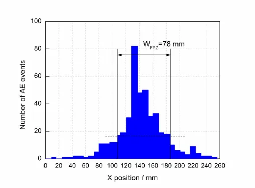
The indirect observation method refers to observing other physical parameters related to the process of fracture expansion, and indirectly obtaining the observation of the fracture process zone by relational calculation. At present, the indirect observation methods used by researchers are: dye penetration [31, 32], embedded graphite rods [33], laser speckle interferometer [34], ultrasonic measurement [35], infrared vibro-thermography [36], acoustic emission method [37-40] and digital image correlation method[41-43]. Among those methods, the acoustic emission method and digital image correlation method are the most common method that used for determining the fracture process zone. With the aid of three-dimensional acoustic emission technology, Otsuka and Date [30] measured the distribution range of the fracture process zone of concrete specimens. By analysing the experimental results, Otsuka defined the fracture process zone as containing the approximate area of the acoustic emission event greater than 95 % of the total energy. It can also be said that the distribution of acoustic emission events is very dense within this range. The test results showed that:
1) With the increase of load, the measurement results of acoustic emission indicated that micro-cracks are formed in the front part of the pre-formed crack; 2) If the initial ligament length is short, the core area of the fracture process zone will not be fully expanded. Muralidhara et al. [44] also used acoustic emission techniques to measure the size and fracture energy of the concrete fracture process zone. In this paper, the distribution area of the fracture process zone is also determined according to the position distribution of the acoustic emission events and the change of the energy release rate ratio corresponding to different load stages. Mihashi et al. [45] used three-dimensional acoustic emission technology in the double cantilever beam test to observe that the fracture process zone is actually a three-dimensional structure. The propagation of micro-cracks is not limited to the surface of the specimen but is randomly distributed around the main crack.Wu et al. [41] measured the size of FPZ and the corresponding crack opening displacement during the test loading process of concrete three-point bending beam specimens with different sizes and initial seam height ratios by digital image correlation method. The results showed that the FPZ length at the peak load and the maximum FPZ length increase with an increase in specimen height, but decrease by increasing the notch depth to specimen height ratio.
With the help of all the methods mentioned above, the mechanisms that are responsible for the fracture process in concrete have been reported. The toughening mechanisms[46] like micro-crack shielding, aggregate bridging, crack deflection, crack tip blunting, crack surface roughness induced closure and crack branching as shown in Figure 1. 2.
a) b)
c) d)
e) f)
Figure 1. 2 Some toughening mechanisms in fracture process zone: a) crack shielding; b) crack deflection; c) aggregate bridging; d) crack surface roughness-induced closure; e) crack tip blunted by void; f) crack branching[8]
Usually, the influence of all these mechanisms mentioned above is lumped together and taken into account by a conceptual fracture process zone. So when one applies fracture mechanics to
Microcracks
Main crack Main crack Aggregate
Aggregates Friction between crack faces
Void
Main crack Secondary crack tip
1.1 Introduction to the fracture process in concrete
9
concrete, the fracture process zone needs to be understood and determined. There are no standard methods to determine the width of FPZ experimentally, some researchers used the equation below to calculate the approximate width of the fracture process zone[47].The value that calculated from the equation is just an effective width corresponding to linear stress-strain curve and uniform strain distribution within the fracture process zone is assumed.
1 2 2 f 1 1 FPZ t t G w f E E − = − (1.1)
Where E is the modulus of elasticity; E is the strain-softening modulus; t f is the tensile t
strength of material; G is fracture energy. f
Based on a banding microcrack model (BMM), Yao Wu and Li[48] proposed another equation to calculate the length and width of FPZ as presented below.
2 1 2 c Ic FPZ t k w K l f + = (1.2) 2 9 8 Ic FPZ t K w f = (1.3)
Where k is softening degree; w is critical crack open displacement; c f is tensile strength; t Ic
K is fracture toughness.
Other researchers state that the width of FPZ is proportional to the maximum aggregate size. Bažant et al. [47] reported that the width of FPZ is about three times of the maximum aggregate size, while Chhuy et al.[49] assumed it is as wide as the maximum aggregate size and verified this with the help of ultrasonic detective test. Moreover, the length of FPZ is about 0.368 - 0.684 of specimen ligament as reported by Alexander[50, 51]. Shah [52] has studied the impact of specimen depth on the measured value of FPZ and reported that with the increase of specimen ligament, the length of FPZ increases and gradually approaches to a constant value. In the fictitious crack model [18], a parameter known as characteristic length (l ), is imported to combine tensile strength (ch f ) and t
fracture energy (Gf ) and can be expressed as:
2 f ch t EG l f = (1.4)
It is assumed that characteristic length (l ) is a purely material property and is proportional to ch
the length of the fracture process zone. The characteristic length value for concrete approximately ranges from 100 mm to 400 mm[53]. However, the length of the FPZ at a complete separation of the initial crack tip in concrete is in the range of 0.3l and 0.5ch lch [8].
1.1.2 Impact of ITZ on fracture behaviour
It is now known that the properties of ITZ impact the mechanical properties of concrete. According to previous studies, the thickness of ITZ is controlled by the wall effect[54, 55]. There are also other factors that influence the thickness of ITZ like water-cement ratio, aggregate size, aggregate type, aggregate shape, aggregate surface conditions, cement, and admixtures [56-59]. Generally,
researchers consider that the lower the water-cement ratio, the thinner the ITZ[60]. Simenow et al. [57] found that the type of aggregate has a greater influence on the overall properties of ITZ. Moreover, for concrete with larger aggregate size, the thickness of ITZ becomes larger[60]. Elsharief et al. [61] concluded that when the aggregate size decreases, a lower porosity and higher unhydrated cement grains occurred in the ITZ. The researchers [56, 58, 59] also found that the interfacial bond is the deciding factor for tensile strength while has little influence on the compressive strength. Grondin and Matallah [62] numerically studied the effect of ITZs on the mechanical behaviour of concrete at the mesoscopic scale and found that the maximum strength of the concrete depends on the local tensile strength of the ITZs. Skarżyński et al. [14] investigated the cracking process in normal concrete through experiments and the results showed that the crack mainly propagates through ITZs and rarely propagate through a single weak aggregate. Nitka et al. [63] studied the effect of strength and number of ITZs by numerical modelling of the three-point bending test. They concluded that the strength and stiffness of the beam increase with the increase of ITZs strengths and with the decrease of the number of ITZs; however, the beam brittleness decreases with increasing number of ITZs and reducing the strengths of ITZs.
1.2 Theoretical models for quasi-brittle fracture in concrete
In order to investigate the issue of concrete fracture, researchers have mainly adopted three methods: 1) when fracture process zone size is relatively small when compared with the structure size, fracture toughness or energy release rate criterion based on linear elastic fracture mechanics can be used to analyse the fracture of concrete structure; 2) when the effect of fracture process zone needs to be considered, in order to simplify the calculation procedures, a nonlinear model based on linear elastic fracture mechanics can be used to describe the fracture process of concrete; 3) directly introducing non-linearity and/or considering FPZ when analysing fracture problems of concrete structures.
The main theoretical fracture or damage models able to describe the fracture characteristics of quasi-brittle materials such as concrete are successively presented in the following.
1.2.1 Cohesive Zone Model
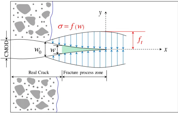
The initial cohesive model was proposed by Dugdale[64] and Barenblatt et al.[65]. In the model, the propagation of a cohesive crack is considered as a fictitious crack which was able to transfer the stress from one face to the other. In 1976, based on the previous concepts, Hillerborg et al. [18] developed the fictitious crack model (FCM) to illustrate the nonlinear behaviour of the concrete material. The model assumed that: 1) there exists a fracture process zone ahead of a developed crack which is defined as a fictitious crack; 2) the stresses transfer through the fracture process zone depend on the opening width of the fictitious crack (w) following a characteristic strain softening behaviour of the material; 3) the fracture process zone begins when the maximum stress at the fictitious crack tip reaches the tensile strength of the material and after this stage the stress decreases according to the strain softening behaviour, as shown in Figure 1. 3, until the crack opening width becomesw ; 4) 0
1.2 Theoretical models for quasi-brittle fracture in concrete
11
Figure 1. 3 Stress distribution and cohesive crack growth for fictitious crack model
As mentioned above, the stress transferred through the cohesive crack (𝜎) was assumed as a function of the crack opening displacement (w) expressed as:
( )
f w = (1.5)
Where f is a function characteristic of the material that must be determined from experiments. According to Figure 1. 3, it should be noted that two properties are very important in the cohesive crack model: the tensile strength ( f ) and the cohesive fracture energy (t Gf ). The tensile strength is
the stress at which the cohesive crack is created (formation of FPZ) and starts to open. The external energy required to create and fully break a unit surface area of cohesive crack is equal to the cohesive fracture energy. It can be given as the area under the softening curve by the following expression.
( )
0 0 w f G =
f w dw (1.6)The fictitious crack model considers that the softening curve is the fundamental parameter to represent the local microstructure based properties of the material and is independent of the geometry and size of the structure. When the tensile strength, fracture energy, and the shape of the softening curve are known, the softening behaviour of a material can be determined. Based on the experimental studies, softening curves with varies shape have developed, such as linear softening curve[18, 66], bilinear softening curve[53, 67-71], trilinear softening curve[72], exponential softening curve[73, 74] and power function softening curve[75].
1.2.2 Crack Band Model
Cracks in the concrete generally propagate tortuously and randomly around its aggregates instead of a straight line. Also at the crack tip, there exists an area named the fracture process zone,
Real Crack C M O D
w
( )
f w
=
t
f
x
Fracture process zone 0
w
which consists of distributed microcracks. Take into account these assumptions, Bažant and Oh [47] proposed a model called blunt crack band model (CBM) to simulate the fracture behaviour of concrete. The model considers the fracture process zone as a band of uniformly and continuously distribution microcracks with a fixed width h , as shown in Figure 1. 4. In this model, material fracture properties c
are characterized by three parameters: the fracture energy (G ), the maximum uniaxial tensile f
strength ( f ) and the width of the crack band (t h ) which defines the fracture process zone ahead of c
a crack tip,and is represented in the model by the characteristic length (l ) of the material. ch
Figure 1. 4 Microcrack band fraction [47]
A simple stress-strain relationship is adopted to simulate the stable crack propagation as presented in Figure 1. 5.
Figure 1. 5 Stress-strain curve for the micro crack band [47]
Then the energy consumed due to the crack advance per unit area of the crack band can be calculated from the area under the stress-strain curve and the width of the crack band.
2 1 2 t f c t f E G h E E = + (1.7)
Where E is the modulus of elasticity; E is the strain-softening modulus; t f is the tensile t
strength of material; h is the width of the crack band. c
P P Open microcracks Closed microcracks 0 a a f G t f E t E 1 1
1.2 Theoretical models for quasi-brittle fracture in concrete
13
1.2.3 Equivalent Elastic Crack Model
In the study of concrete fracture properties, in order to facilitate analytical analysis, many researchers have proposed various fracture models based on linear elastic fracture mechanics (LEFM), considering fracture toughness as parameters, such as two-parameter fracture model [76], equivalent fracture model [77], size effect model [78], etc.. Most of these models use the critical stress intensity factor s
Ic
K to determine the critical state of concrete cracks. However, K can only reflect the Ics
critical state of concrete crack instability. Another approach is to use the resistance-curve (R-curve) [79]. Based on the framework of equivalent LEFM, Morel et al. [80-82] assumed that the increase of the structure compliance due to the development of FPZ is attributed to the propagation of an elastically equivalent crack and the resistance to crack growth balances the elastic energy release rate. Thus, an R-curve behaviour can be obtained for quasi-brittle fracture corresponding to the dependence of the critical energy release rate required for fracture growth on the elastically equivalent crack length. Typically, the R-curve is described in terms of fracture energy, or stress intensity, and the stable and unstable crack growth can be distinguished by using this R-curve.
Two-parameter fracture model (TPFM) was developed by Shah and Jenq [76]. The model is based on the fracture mechanics and puts forward some nonlinear concrete mechanics assumptions. The fracture process of concrete is determined by two parameters: the critical stress intensity factor ( s
Ic
K ) and the elastic critical fracture tip opening displacement (CTOD ). In 1990 RILEMc [83]
adopted this model as the standard experimental method to determine the fracture parameters. However, this model does not consider the influence of plastic deformation on the crack propagation when measuring the parameters.
Effective crack model (ECM) was proposed by Karihaloo and Nallathambi[77]. The model is based on the effective-elastic crack approach and the fracture toughness of concrete is determined by the three-point bending test. The basic concept of this model is similar to the two-parameter fracture model. The two fracture control parameters of the model are: the critical equivalent crack length (a ) e
and the equivalent crack tip critical stress intensity factor ( e Ic
K ). In this model, secant compliance at
the maximum load is used to determine the effective-elastic crack length, while in the two-parameter fracture model using the elastic part of the unloading compliance. Due to the fact that the secant compliance at the maximum load includes effects of both elastic and inelastic deformation, so the value that calculated is greater than that obtained by the two-parameter fracture model.
Bazant and Kazemi [84] used a series of geometrically similar structures to investigate the fracture of quasi-brittle materials. The fracture behaviours of the materials are simulated by introducing an effective-elastic crack. The equations for the critical energy release rate and the critical crack extension for an infinitely large structure are given as below.
2 2 0 0 2 t f n B f D a G g Ec D = (1.8)
(
)
(
0)
0 ' 0 f g a D c D g a D = (1.9)Where a is the initial crack length; 0 B and D are constant; 0 E is the modulus of elasticity;
t
f is the size-independent tensile strength of a material; c is a coefficient representing different n
types of structures, c = for a tensile plate and n 1 cn =1.5S D for a beam ( S is the span and D
1.2.4 Damage Models
Damage mechanics mainly deal with the macroscopic mechanical effects caused by the generation and development of microscopic defects in the material and the processes and laws that lead to material damage. The goal of damage mechanics is to predict the material response when damage initiates at a certain stress-strain state and propagates as the applied loads increase the stresses in the material. All materials show some level of damage at a very small scale. Damage is controlled by a state variable (D) which has a value between 0 (virgin material) to 1 (completely damaged
material). Loss of stiffness as damage evolves is incorporated into the stiffness matrix (Equation 1.
4) and it is also a direct representation of the stress state of the material (Equation 1. 5).
(
1)
dam und C = −D C (1.10)(
)
: 1 : dam und C D C = = − (1.11)Where Cdam is damaged stiffness matrix; Cund is undamaged stiffness matrix;
is stress tensor;
is strain tensor.The damage models can be roughly divided into two parts: 1) isotropic damage model[85-88]; 2) anisotropic damage model[89-95]. Løland[85], Krajcinovic [87, 88] and Mazars[86] considered damage as a scalar and established an isotropic damage model of concrete using the concept of effective stress. When dealing with the unilateral stress performance of concrete, Mazars [96] used two different damage variables to reflect tensile damage and compression damage. Ladevèze et al. [97] decomposed the Cauchy stress tensor into ‘positive’ and ‘negative’ parts, and the damage is still considered as a scalar, but a crack closure factor is introduced to account for the different effects of damage on stretching and compression. In the theory of anisotropic damage, Ortiz [95] first realized that although the average damage direction is perpendicular to the direction of compressive stress when concrete is subjected to uniaxial compression, the micro-cracks expand and merge along the coarse aggregate interface and the expansion direction is curved; so the damage has a lateral effect. According to this consideration, Suaris et al. [98] and Voyiadjis et al. [99] proposed the concept of effective compliance tensor, and established an anisotropic damage model of concrete. The evolution of damage is determined by the theory of the bounding surface.
1.3 Numerical modelling methods for concrete
In previous studies, the fracture behaviour of concrete has been studied using different numerical methods such as the finite element method (FEM) [18, 100, 101], the boundary element method (BEM) [102-104], the discrete element method (DEM) [105-107], the numerical manifold method [108-110], the discontinuous deformation analysis (DDA) method [111] and the mesh free method [112, 113]. All these methods mentioned can be roughly categorized as a continuum approach and discrete approach.
1.3 Numerical modelling methods for concrete
15
1.3.1 Continuum Approach
1.3.1.1 Finite Element Method
In the continuum approach, FEM is one of the most widely used modelling methods and can date back to the early 1960s [114, 115]. Firstly, Clough [115] used FEM to solve the problems of plane stress, now it has become the mainstream numerical tool in engineering sciences [18, 116]. The FEM is a numerical modelling method that tries to find approximate solutions to the boundary value problems of differential equations. The general principle of FEM is to divide the domain of the problem into smaller sub-domains called finite elements. Then it does the local approximation inside each finite element, performs the finite element assembly and finds the solution of the global matrix equation. FEM has great robustness and flexibility to deal with problems like material heterogeneity, non-linear deformability, complex boundary conditions, in situ stresses and gravity. These advantages make the FEM becoming the most successful numerical method used in engineering and science research [18, 116]. However, there are still some shortcomings for FEM, e.g., the continuum assumption in FEM makes it unsuitable to deal with complete detachment and large-scale fracture opening problems, which are the most concerning issues in the concrete fracture. Beside these demerits, the most difficult thing faced by FEM is the simulation of the fracturing process. Two available methods can be used for modelling of fracturing progress based on FEM: the element degradation approach and the element boundary-breaking approach.
1.3.1.1.1 Element Degradation Approach
The element degradation approach considers the fracturing process as a sequence of element degradation. In the software like ABAQUS[117] provides a deletion technique which removes the elements where the failure criterion is locally reached. Elements deleted can be visualized to mimic the crack progress. The continuum damage mechanics (CDM) is one of the most typical methods based on FEM and is widely applied to brittle fracturing analysis [118]. Based on the equivalent continuum concept, another degradation technique is developed. It considers cracks as elastic degradation and/or softening plasticity [119]. Smeared crack model is one representative of this method, which is first introduced by Rashid[120].
No requirement of re-meshing and not adding new degrees of freedom in the calculation process is the principle merits of element degradation method. However, this method cannot give an explicit description of the fracture surface and has the demerits of mesh size and orientation dependency.
1.3.1.1.2 Element Boundary Breaking Approach
The element boundary-breaking approach represents the fracturing process by the separation of inter-element boundaries. Interface elements are inserted along the inter-element boundaries in this method. Failure of an inter-element boundary can be based on the fracture mechanics or failure criteria of the corresponding interface element. Cohesive Zone Model (CZM) [18] is the most successful development of the element boundary-breaking approach. Normally, in order to eliminate the element dependence and the problem of stress singularity which exists in the crack tip, the element
boundary-breaking approach should be combined with meshing techniques. However, for meshing techniques, a rather complex software package is needed to be developed and the use of re-meshing techniques also accumulates the calculation errors through the mapping of variables. The worst problem is that adaptive re-meshing can hardly be used to simulate complex crack development, such as crack coalescence and crack bifurcation.
1.3.1.2 Boundary Element Method
The boundary element method is a numerical method developed since the late 1970s[121], and an early application of the BEM to a crack problem was done by Cruse[122]. In BEM, the value of the field function at the boundary and at each point in the domain can be obtained by transforming the basic governing equations of the known boundary domain into boundary integral equations and then solving the corresponding algebraic equations by discretizing the boundary. The boundary element method only needs to be discretized on the boundary of the domain. Therefore, it is only necessary to arrange nodes on the boundary and crack surface when simulating cracks. It is not necessary to re-mesh when simulating crack propagation. BEM is more suitable for solving problems of homogeneous and linearly elastic bodies; however, it poses many problems in solving some problems like material heterogeneity, nonlinear material behaviour, and damage evolution process.
1.3.2 Discontinuum Approach
1.3.2.1 Discrete Element Method
The discrete element method (DEM) is the representative discontinuum method which was initially developed for solving rock mechanics problems by Cundall [123]. The key concept of DEM is to divide the domain of interest into an assemblage of rigid or deformable blocks/particles/bodies [124, 125]. DEM methods can be divided into two categories: explicit ones and implicit ones. There exist two kinds of approaches for the explicit DEM methods, namely the dynamic relaxation method and the static relaxation method. The static relaxation method uses equations of equilibrium to obtain the displacement of particles at the next time step. However, for dynamic problems, the static relaxation method cannot be used. Dynamic relaxation based DEM use Newton’s second law to get the displacement of particles at the next time step, and it is generally called the distinct element method. The details of dynamic relaxation based DEM will be introduced in Chapter 2. The distinct element method can simulate the complex mechanical interactions of a discontinuous system. Now there are many researchers [126-130] who have successfully used DEM to model the fracture behaviours of concrete.
1.3.2.2 Lattice Method
The Lattice model is a simulation model of the grid system consisting of discrete continuum bodies separated into rods and beams. The Lattice model was first proposed by Hrennikoff [131] in 1941 and was called the framework method at that time. The method divides the continuum body into a truss, which is mainly used to solve classical elastic mechanics problems. The Lattice model has a
1.4 Numerical method used in the thesis
17
clear idea and a simple unit model. It is more suitable for the study of the failure mechanism of non-uniform materials such as rock[132] and concrete[133] under simple loading conditions.
One of the most widely used lattice models is the Beam Lattice model proposed by Schlangen et al. [134] as shown in Figure 1. 6. The Beam Lattice model assumes that the concrete is composed of meso-level beam elements, and the mechanical parameters of the beam elements are determined by the properties of the mesostructure components such as aggregates and cement mortar. The beam element can transmit axial force, shear force and bending moment. When the stress state of the beam satisfies the given strength criterion, the beam element is removed from the grid and the crack is generated and developed.
a) b) c)
Figure 1. 6 Beam Lattice model diagram: a) Regular triangular lattice of beams; b) External forces and deformations on a single beam element; c) stress-strain relation for an element [134]
1.3.2.3 Extended Finite Element Method
Extended finite element method (X-FEM) is proposed by the research group of Belytschko [135, 136] in 1999, which is based on the unit decomposition theory to enhance the displacement function of the traditional finite element. Usually, Heaviside function and asymptotic functions are used to deal with the discontinuity and singularity. The level set method (LSM) [137], which is developed by Osher and Sethian [138], is introduced to describe the motion of interface, and the crack propagation is tracked in real time. So the X-FEM algorithm allows the crack passing arbitrarily through elements by incorporating enrichment functions to handle the field discontinuities. Particularly, elements containing a crack do not need to conform to crack edges and mesh generation are much simpler than in classical FEM [135]. Moreover, the X-FEM solves the problem that the finite element needs to continuously re-mesh the mesh when simulating crack propagation, and it is not necessary to separately divide the crack tip portion into a high-density mesh.
1.4 Numerical method used in the thesis
For those methods mentioned, some of them [139, 140] modelled concrete as a bi-phase material. It is not appropriate as aforementioned that the behaviour of ITZ is very important in the fracture of concrete. Hence, researchers now supposed concrete to be composed of three phases in their modelling. Trawiński [141] has successfully modelled the fracture of concrete by considering concrete as a three-phase material using 3D mesoscale finite element method (FEM). The parametric analysis of their studies has shown that the properties of matrix and ITZ have influences on the peak
i Q Mi i F Fj j M Qj i v i i u uj j vj t f
strength and brittleness of concrete beam under three-point bending test. Lilliu [142] used a lattice model to model the behaviour of concrete as three-phase and the results also revealed that the strength of ITZ affects the fracture process. Skarżyński [143] used DEM to simulate concrete as a three-phase composite and found that the mechanical properties of ITZs had a pronounced influence on the material strength and macro-cracking.
For the methods mentioned above, FEM is based on either continuum damage mechanics or fracture mechanics, and is being used for the description of deformable continuous bodies. On the contrary, DEM describes particulate materials, usually modelled by perfectly rigid particles and their interactions determined from fictitious overlaps of these rigid particles. The propagation of cracks in concrete is a discrete problem and should look into the local behaviours. Compared with FEM, DEM looks into micromechanics of problem and allows a grain level control and can solve the discontinuous problem. So it is suitable for modelling the fracture of concrete. In this thesis, DEM is adopted to model the size effect and the aggregate effect of concrete.
1.5 Summary
In this chapter, different fracture models of concrete behaviour are investigated. Fracture process zone is a key parameter that influences the fracture behaviours of concrete. Although different methods are proposed by researchers, it is still a problem that needs to be solved. Besides, the properties of ITZ seem to have a great impact on the mechanical properties of concrete. So the influence of ITZ needs to be studied later. Then the theoretical models and the numerical modelling methods used for concrete are presented. Based on fracture mechanics or damage mechanics, different theoretical models for concrete are proposed. Next, the most widely used numerical methods for concrete are introduced and those methods can be roughly divided into two categories: continuum models and continuum models. Compared with the continuum-based models, discontinuum based models seem more appropriate to model the fracture behaviours of concrete. So in the next chapter, the discrete element method is employed to model the fracture behaviours of concrete.
19
Chapter 2
A Comprehensive Approach for Numerical
Modelling of Concrete by Discrete Element
Method
This chapter describes a comprehensive approach for modelling mechanical and fracture behaviour of concrete using discrete element method (DEM). Concrete is modelled at mesoscale as a three-phase material composed of aggregates, mortar, and interface. The complete coarse aggregate grading curve is considered in the mesostructure. A systematic approach has been used in this study to determine local micro parameters for each phase of concrete using inverse calibration. An improved contact model that can satisfy the quasi-brittle behaviour and low tensile to compressive strength ratio (as in case of concrete) is used.
20
2.1 Brief history of the development of Discrete Element Method
The discrete element method (DEM) is a method firstly proposed by Cundall[123] in the early 1970’s to model the progressive failure of a discrete block system. The interaction between blocks was governed by friction and normal stiffness. However, whenever blocks were touching or separated, there was no limitation to the amount of displacement or rotation of each block in the model. It was designed for rigid body motion problems which were impossible to be solved by finite element methods (FEM) at that moment. The basic theory of DEM was also given Cundall, i.e. force-displacement law, the law of motion and computation cycles with time steps.
Cundall and Strack [124] then applied the DEM method to model the granular assemblies to study the particle contact force distributions in the assemblies. This granular medium was composed of distinct particles which displaced independently from one another and interacted with others at discrete contact points. Further development of DEM was made by Cundall, Drescher, and Strack [144] in the early 1980’s who introduced the methodologies of measuring and observing granular assemblies using Ball simulation. In the late 1980’s, Cundall extended 2D particle simulation to a 3D version which was known as TRUBAL[145]. The numerical modelling results were in accordance with the experimental results of Ishibashi et al.[146], except for the volumetric strain measured from tri-axial tests. Almost at the same period, Thorton et al. [147] developed a modified version called GRANULE. In their model, they attributed a surface energy to the balls in the agglomerates so that tensile forces between balls were defined as auto-adhesive. The program was able to model the fracture of an agglomerate of spherical balls bonded together. After that, the DEM has been developed rapidly, with applications in different domains like rock/soil mechanics[128], chemical engineering [148] and pharmacy[127].
2.2 State of the art on Discrete Element Method
The initial application of DEM to study the fracture of brittle materials such as concrete is dated back to the 1980s. Meguro and Hakuno [149, 150] developed a modified distinct element method (MDEM), based on the basis of Iwashita’s model, to study the dynamic fracture of a masonry concrete wall. The results were in accordance with the actual seismic damage observed after past earthquake. Then Takada and Hassani [151] used MDEM to investigate compression failure of reinforced concrete in the 2D aspect, the quantitative results were in reasonable agreement with the experimental ones. After that, interest in using DEM to model the behaviours of concrete increased rapidly. DEM was mainly applied to investigate the fracture of concrete at a high strain rate[152]. Monteiro et al. [153] combined FEM and DEM to model the development of cracks when concrete was under the effect of the moment. Pan et al. [154] modelled the deterioration of concrete at meso-scale caused by the alkali-aggregate reaction. Although DEM is now widely used to model the behaviours of concrete, there still remain some problems.
Aforementioned, concrete is three-phase composite and coarse aggregate occupies about 45 % of the volume of concrete. How to model the coarse aggregate properly? Generally there exist three methods to generate aggregates: 1) each aggregate is represented as a single big ball; 2) each aggregate is represented as a clump of several small balls joined together with no breakage of
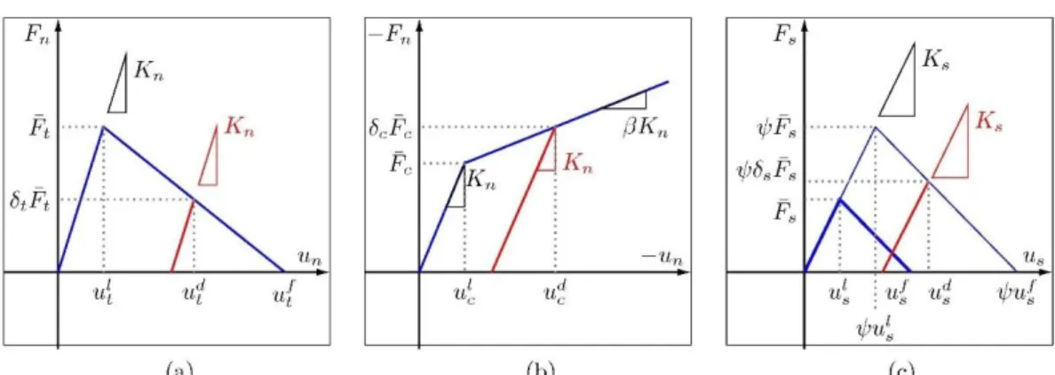
![Figure 2. 3 The constitutive relationships in normal and shear directions of the model [165]](https://thumb-eu.123doks.com/thumbv2/123doknet/14526236.723017/35.892.212.682.770.1033/figure-constitutive-relationships-normal-shear-directions-model.webp)
![Figure 2. 5 Normal force-displacement contact law for the modified parallel bond [169]](https://thumb-eu.123doks.com/thumbv2/123doknet/14526236.723017/36.892.260.649.580.868/figure-normal-force-displacement-contact-modified-parallel-bond.webp)
![Figure 3. 8 The schematic of the 3D location of an AE source [258]](https://thumb-eu.123doks.com/thumbv2/123doknet/14526236.723017/74.892.306.597.108.502/figure-schematic-d-location-ae-source.webp)