HAL Id: tel-00327414
https://tel.archives-ouvertes.fr/tel-00327414
Submitted on 8 Oct 2008HAL is a multi-disciplinary open access archive for the deposit and dissemination of sci-entific research documents, whether they are pub-lished or not. The documents may come from teaching and research institutions in France or abroad, or from public or private research centers.
L’archive ouverte pluridisciplinaire HAL, est destinée au dépôt et à la diffusion de documents scientifiques de niveau recherche, publiés ou non, émanant des établissements d’enseignement et de recherche français ou étrangers, des laboratoires publics ou privés.
Analysis and Optimization of a New Family of Parallel
Manipulators with Decoupled Motions
Sébastien Briot
To cite this version:
Sébastien Briot. Analysis and Optimization of a New Family of Parallel Manipulators with Decoupled Motions. Automatic. INSA de Rennes, 2007. English. �tel-00327414�
THESE
Présentée le 20 juin 2007
Devant l’Institut National des Sciences Appliquées de Rennes
En vue de l’obtention du
Doctorat de GENIE MECANIQUE
Par : Sébastien BRIOT
N° d’ordre : D-07-07
Analyse et Optimisation
d’une Nouvelle Famille de Manipulateurs Parallèles
aux Mouvements Découplés
Directeur de Thèse : Vigen ARAKELYAN
Membres du jury :
BIDAUD Philippe
Professeur des Universités
Président
GOGU Grigore
Professeur des Universités
Rapporteur
WENGER Philippe
Directeur de Recherche CNRS
Rapporteur
Abstract
It is well known that, amongst the numerous advantages of parallel manipulators when compared with their serial counterparts, one can notice better velocities and dynamic characteristics, as well as higher payload capacities. However, there are some drawbacks, such as a smaller workspace, a high coupling in the kinematic relationships and more constraining singularities. In order to overcome these disadvantages, the decoupling of the movements of parallel robots has been proposed.
Thus, the research project deals with the design, the optimization and the improvement of a new family of parallel manipulators from 3 to 6 degrees of freedom named PAMINSA (PArallel Manipulator of the I.N.S.A.). The second part of this manuscript presents the characteristics of these architectures, namely the decoupling between the movements of the platform in the horizontal plane from its translations along the vertical axis.
In a third section, we analyse the singular configurations of these manipulators. This analysis is necessary in order to choose the manipulator which has the largest singularity-free workspace.
In sections 4 and 5, we propose novel methods allowing an increase in the size of their singularity-free workspace. The first solution is based on the use of mechanisms with variable structures, i.e. mechanisms of which structural parameters can be altered. Such a solution makes it possible to increase the singularity-free workspace to 100% of the maximal workspace. The second solution deals with the optimization of the dynamic parameters of the manipulators, which makes it possible to pass through the singularities during the displacements of the manipulator.
Finally, in a sixth section, a new, fast and efficient method of computing the accuracy of PAMINSA manipulators is described. In addition, solutions for the improvement of functional characteristics of PAMINSA manipulators are proposed.
Foreword
Before beginning this manuscript, I would like to say a few words for people who have shared time with me and supported me during these past three years.
Firstly, I am very much obliged to my research supervisor, the Prof. Vigen Arakelian, for his tremendous support and his unfailing faith in me. With his comprehensive experience in mechanism and machine theory, he has been a mentor and a great source of ideas. His quiet leadership, a perfect balance between providing direction and encouraging independence, has been a guiding inspiration for me.
I am also grateful to Prof. Victor Glazunov of the Russian Academy of Science. During the three months he passed in Rennes, he helped me understand the screw theory concept. Without this knowledge, I would not have been able to complete some important parts of my thesis. His kindness, patience and our shared affinity for music have left me with wonderful memories.
I would like to thank Dr. Ilian Bonev who supervised me during a three-month visit to his laboratory in Montreal. This stay was very important for me and, through our long discussions, Ilian contributed to my better understanding of certain kinematic concepts. I would also like to thank Prof. Philippe Wenger and Dr. Damien Chablat of the IRCCyN of Nantes for the time they have spent with me and their wise advice during the editing of several articles.
I would like to express my gratitude to Dr. Sylvain Guegan who completed the electronics and the control of the prototype. He also supported me during the experimental validations of my theoretical results, which would never have been completed without his help.
I would like to acknowledge Dr. Eric Courteille for his useful comments and advice during the edition of this dissertation, as well as for his participation in experimental tests.
Special thanks are also due Prof. Jean Le Flecher and to all the members of the C.C.M. (Manufacturing Centre of Mechanics) of I.N.S.A. Without them, and their wonderful and meticulous work, the prototype would never have been so perfectly
Foreword.
iv
I would like to thank the English teachers (Mr. Garrett Moran and Mrs. Ann Cochennec) who voluntarily improved the quality of several papers and parts of this dissertation by their judicious advice and comments.
I also wish to express my gratitude to my thesis defence committee and especially to Profs. Grigore Gogu and Philippe Wenger. Their detailed comments and valuable suggestions have contributed to the quality of this manuscript.
I would like to address a particular acknowledgment to my friend Cedric Baradat, who is finishing its Ph. D. thesis at this time. We have spent very good moments together. I hope that he will enjoy his new life in Montpellier and will have more time to devote to his wife Morgane and their baby Leo. I would also like to address special thanks to the other (current or past) Ph. D. students of our research team (Amine, Behnam, Cunsheng, Dominique, Galou, Mathieu and Sarik). Without them, the work atmosphere would not have been so good. Not forgetting my friend Benjamin Fuchs with whom I have had long discussions about our respective job problems and career projects. I wish him good luck for the future.
I address a special thank to Veronique Martin, Simon Lessard and to Dr. Stephane Caro who made my stay in Montreal one of the greatest memories I will have from this past three years.
I would like to thank the secretaries (Alex, Lily and Vero) of the G.M.A. department and the G.C.G.M. laboratory of I.N.S.A. for their efficiency, kindness and for the good times we have spent during coffee breaks. Thank you to the other technical employees and the teaching team.
Last, but not least, I would like to express all my gratitude and my love to my family and to my girlfriend Sylvie. I am not sure this thesis would have been a success if their patience, comprehension and love had not always been there for me. With these few lines, I would like to express to them how much their presence is necessary to my happiness. Thank you very much.
To the woman I love, To my parents.
Contents
Abstract... i
Foreword ... iii
Contents ... vii
List of Figures ... xi
List of Tables... xvii
Nomenclature ... xix
Introduction ... 1
1. Parallel Robots: from the Gwinnett Platform to the Tripteron ... 5
1.1. The historical evolution of parallel robots ... 6
1.1.1. At the beginnings ... 6
1.1.2. Prototypes and industrial applications of parallel manipulators... 10
1.2. Towards the kinematic decoupling of parallel structures... 16
1.2.1. From the decoupling between position and orientation ... 16
1.2.2. ... to the full-decoupling of the movements ... 22
1.3. Summary ... 26
2. PAMINSA: A New Family of Decoupled Parallel Manipulators ...29
2.1. Design analysis of PAMINSA manipulators ... 30
2.1.1. A new approach to the problem of the design of decoupled parallel manipulators ... 31
2.1.2. Mechanical architecture of PAMINSA ... 31
2.1.3. The manipulators from 3 to 6 DOF ... 37
2.1.4. A particular structure with 3 fully-decoupled translatory motions... 41
Contents.
viii
2.3.1. Workspace analysis ... 46
2.3.2. On the design of the prototype elements ... 48
2.3.2.1. Design of the pantograph linkages ... 49
2.3.2.2. Design of the passive prismatic pairs ... 50
2.3.2.3. Design of the guides of the vertical limbs BiGi ... 51
2.3.2.4. Motorization for the horizontal displacements ... 52
2.3.2.5. Motorization for the vertical translations... 53
2.3.3. Experimental validation of the decoupling concept ... 54
2.4. Summary ... 55
3. Singularity Analysis of PAMINSA Manipulators... 57
3.1. Determination of the singularity loci ... 58
3.1.1. Inverse kinematics of PAMINSA manipulators ... 59
3.1.2. Singularity analysis of the PAMINSA-6D3L ... 60
3.1.3. Singularity analysis of the PAMINSA-5D3L ... 64
3.1.4. Singularity analysis of the PAMINSA-4D3L ... 65
3.1.5. Singularity analysis of the PAMINSA-4D3L* ... 65
3.1.6. Singularity analysis of the PAMINSA-3D3L* ... 66
3.1.7. Singularity analysis of the PAMINSA-4D2L... 66
3.2. The self motions of PAMINSA manipulators ... 67
3.2.1. Direct kinematics of the 3-RPR planar parallel manipulator ... 68
3.2.2. Analysis of self motions... 74
3.2.2.1. Design conditions leading to Cardanic self motions ... 75
3.2.2.2. Kinematic analysis of the Cardanic self motion ... 77
3.2.3. Examples and experimental validations ... 80
3.3. Summary ... 83
4. Increase of Singularity-Free Zones in the Workspace of PAMINSA Manipulators Using Mechanisms of Variable Structure ... 85
4.1. The quality of motion transmission and the pressure angle ... 86
4.1.1. The pressure angle ... 86
4.1.2. Application on the PAMINSA-4D3L ... 87
4.2. The legs with variable structure ... 92
4.3. Plotting of singularity-free zones taking into account the pressure angles...93
4.4. Trajectory planning ... 97
4.4.1. Example 1 ... 98
Contents.
4.5. Summary ...103
5. Determination of Optimum Dynamic Parameters of Parallel Manipulators for Passing through the Singular Positions ...105
5.1.
Path planning of parallel manipulators in the presence of singular positions ... 106
5.2. Optimal dynamic conditions for passing through Type 2 singularities ...107
5.3. Illustrative examples ...110
5.3.1. Planar 5R parallel manipulator ...111
5.3.1.1. Inverse dynamics...112
5.3.1.2. Motion Planning ...114
5.3.2. PAMINSA-4D3L...117
5.3.2.1. Inverse dynamics...117
5.3.2.2. Motion Planning ...119
5.4. Experimental validation of obtained results ...124
5.5. Summary ...125
6. Optimization of PAMINSA Manipulators ...127
6.1. Accuracy analysis ...128
6.1.1. Mathematical background ...130
6.1.2. Analysis of the orientation and position errors...133
6.1.2.1. Maximum orientation error ...133
6.1.2.2. Maximum position error ...135
6.1.2.3. Conclusions ...139
6.1.3. Examples ...139
6.1.3.1. 3-DOF 3-RPR planar parallel robot ...139
6.1.3.2. 3-DOF 3-PRR planar parallel robot ...143
6.1.4. Conclusion ...147
6.2. Minimization of the deformations ...147
6.2.1. Accuracy analysis ...148
6.2.2. Improvement of positioning accuracy of PAMINSA by means of correcting systems mounted on the drive system ...151
6.2.3. Improvement of positioning accuracy of PAMINSA by means of correcting systems mounted on the platform ...154
6.2.4. Conclusions ...156
Contents.
x
6.3.2. Reduction of input torques in dynamic mode of operation ...158 6.3.3. Experimental validations ...161
6.3.3.1. Reduction of input torques in static mode of operation ...161 6.3.3.2. Reduction of input torques in dynamic mode of operation .162 6.4. Summary ...165
Conclusion ...167
Bibliography...173
Appendix A. Computation of the Coordinates of the Pantograph
Linkages Centre of Masses ...189
Appendix B. Expressions of the Terms of the Conics Representing the Singularity Loci ...195
Appendix C. Expressions of the Intermediary Terms for the Analysis of
the Self Motions ...197
Appendix D. Expressions of the Terms for the Inverse Dynamics of the PAMINSA-4D3L ...199
Appendix E. Characteristics of the PAMINSA Used for the Numerical Simulations ...207
Appendix F. List of Publications about Presented Works ...209
List of Figures
Figure 1.1. Possibly the first spatial parallel mechanism [Gwinnett 1931]... 6
Figure 1.2. The first octahedral hexapod [Gough 1962] ... 7
Figure 1.3. The Stewart platform [Stewart 1965]... 8
Figure 1.4. Various applications of the Gough-Stewart platform... 8
Figure 1.5. Schematic of the Delta parallel robot from Prof. Clavel’s patent [Clavel 1990] ... 9
Figure 1.6. Various applications of the Delta robot ...10
Figure 1.7. Examples of parallel manipulators ...13
Figure 1.8. The decoupled parallel manipulators proposed in [Patarinski 1993] ...17
Figure 1.9. The double parallel manipulators proposed in [Lee 1995] ...18
Figure 1.10. Architecture of the Nabla 6 ...19
Figure 1.11. Architecture of the Polman-6 ...20
Figure 1.12. Structures decoupled between position/orientation with various DOF ...21
Figure 1.13. Other kind of partial decoupling [Jin 2004] ...22
Figure 1.14. Examples of fully-isotropic manipulators proposed by Prof. Gogu ...24
Figure 1.15. Examples of fully-decoupled manipulators with 3 translatory DOF: (a) and (b), two manipulators designed in [Carricato 2004b], (c) and (d), two possible arrangements of manipulators called Tripteron presented in [Gosselin 2004] and [Kong 2002] ...25
Figure 2.1. Gravity work in space: motions in the horizontal plane and along the vertical axis ...31
Figure 2.2. Scheiner pantograph linkage ...32
Figure 2.3. Control of the displacement of the pantograph linkage ...32
Figure 2.4. PAMINSA with 4 DOF (a); kinematic chain of each leg (b) ...33
Figure 2.5. Kinematic models for the displacements of the manipulator under study ...34
List of figures.
xii
Figure 2.6. The angle of the inclination ψ of the platform for the
PAMINSA-5D3L ...40
Figure 2.7. Fully-decoupled PAMINSA with 3 DOF ...41
Figure 2.8. Joints and links description for the static analysis of the studied manipulator ...43
Figure 2.9. CAD model of the PAMINSA manipulator ...45
Figure 2.10. Workspace of the prototype of PAMINSA ...47
Figure 2.11. Prototype of the PAMINSA manipulator ...49
Figure 2.12. CAD model of a pantograph linkage of the PAMINSA manipulator ..49
Figure 2.13. CAD model of an optimized pantograph linkage ...50
Figure 2.14. CAD model of a profile rail guide ...51
Figure 2.15. Design of the guides of the vertical limbs...52
Figure 2.16. Actuation system of each leg ...52
Figure 2.17. Position of the platform for z = —0.6 m and φ = 0 deg ...54
Figure 2.18. Input torques/effort on the actuators with and without an embedded load of 200 N ...55
Figure 3.1. Simplified schematic representation of the i-th actuated leg ...59
Figure 3.2. Schematics of one leg of PAMINSA-6D3L ...59
Figure 3.3. Example of Type 1 singularity ...62
Figure 3.4. Example of Type 2 singularity for PAMINSA-4, 5, 6D3L ...63
Figure 3.5. Example of Type 2 singularity for PAMINSA-3, 4D3L* ...66
Figure 3.6. Example of Type 2 singularity for PAMINSA-4D2L ...67
Figure 3.7. Schematic representation of the studied 3-RPR planar parallel robot ...69
Figure 3.8. Parameterisation of the base and platform triangles ...69
Figure 3.9. Geometric interpretation of the direct kinematics...70
Figure 3.10. Type 2 singularities of the 3-RPR manipulator ...73
Figure 3.11. Cardanic self motion...74
Figure 3.12. Example of Cardanic motion for a 3-RPR planar parallel robot with Rpl = 0.2 m, Rb = 0.35 m, l1 = l2 = 0.05 m, αpl = 36° and βpl = 72° ..75
Figure 3.13. Schematics of a Cardanic self motion of the studied manipulator with Rpl = 0.1 m, Rb = 0.35 m, l1 = l2 = 0.07 m, l3 = 0 m, αb = 30° and βb = 120° ...79
List of figures.
Rpl = 0.1 m, Rb = 0.35 m, αb = 30° and βb = 120°...82
Figure 3.15. Cardanic self motion of the mobile platform of the PAMINSA prototype starting from the configuration x = 0 m, y = —0.25 m, φ = 0° (view from below)...83
Figure 4.1. Planar parallel manipulator 3-RPR...88
Figure 4.2. Representation of the planar parallel manipulator 3-RPR in 3D ...88
Figure 4.3. Leg with variable structure ...92
Figure 4.4. The contrast intensity corresponding to the pressure angle ...94
Figure 4.5. The reachable workspace of the parallel manipulator with modified legs...94
Figure 4.6. Procedure for the determination of the optimal structure of the parallel manipulator taking into account the pressure angles ...98
Figure 4.7. Torques of the actuators ...99
Figure 4.8. Torques of the actuators ... 100
Figure 4.9. Planar parallel manipulator 3-RRR with legs of variable structure .. 101
Figure 4.10. Spatial parallel manipulator 3-RPS ... 102
Figure 4.11. Planar representation of the leg with variable structure ... 102
Figure 5.1. Kinematic chain of the planar 5R parallel manipulator ... 111
Figure 5.2. Type 2 singularities of the planar 5R parallel manipulator... 111
Figure 5.3. Initial, singular and final positions of the planar 5R parallel manipulator ... 114
Figure 5.4. Input torques of the planar 5R parallel manipulator in the case of the sixth order polynomial trajectory planning, obtained by the ADAMS software... 116
Figure 5.5. Input torques of the planar 5R parallel manipulator in the case of the fifth order polynomial trajectory planning, obtained by the ADAMS software... 116
Figure 5.6. Displacement of the PAMINSA along the prescribed straight line (planar equivalent model)...120
Figure 5.7. Input efforts of the PAMINSA in the case of the sixth order polynomial trajectory planning, computed with ADAMS software... 122
Figure 5.8. Input efforts of the PAMINSA in the case of the fifth order polynomial trajectory planning, computed with ADAMS software... 123
List of figures.
xiv
Figure 5.9. Trajectory reproduction on the PAMINSA during the displacement of the platform with the fifth order polynomial law
(view from below) ... 125
Figure 5.10. Trajectory reproduction on the PAMINSA during the displacement of the platform with the sixth order polynomial law (view from below) ... 125
Figure 6.1. Input error bounding box ... 131
Figure 6.2. The leg wrenches applied to the mobile platform...134
Figure 6.3. Pure translational motion following a variation in q3 only... 134
Figure 6.4. Extrema of the first and second type for the function ∆φ2... 134
Figure 6.5. Pure rotational motion following a variation in q3 only ... 136
Figure 6.6. Analysis of a local extremum for which ∂ /x ∂qi is orthogonal to
(
x−x0)
... 138Figure 6.7. Configurations of the 3-RPR parallel manipulator corresponding to local extrema in (a) the orientation error and (b) the position error ... 141
Figure 6.8. Variation in the direction of vector ∂x/∂q1 (degrees) ... 141
Figure 6.9. Maximum orientation and position errors for the 3-RPR manipulator at φ = 0° ... 142
Figure 6.10. Maximum orientation and position errors for the 3-RPR manipulator at φ = 10° ... 142
Figure 6.11. Schematic of the studied 3-PRR manipulator ... 143
Figure 6.12. Configurations of the 3-PRR parallel manipulator corresponding to local (a) minimum and (b) maximum of the orientation error...145
Figure 6.13. Variation in the direction of vector ∂x/∂q1 (degrees) ... 146
Figure 6.14. Max. orientation and position errors for the 3-PRR manipulator (φ = 0°) ... 146
Figure 6.15. Max. orientation and position errors for the 3-PRR manipulator (φ = 10°) ... 146
Figure 6.16. Absolute positioning errors of the platform with orientation φ = 0° at the altitude z = —0.6 m ... 150
List of figures.
Figure 6.17. Absolute positioning errors of the platform along the z-axis with a load of 20 kg (at altitude z = —0.6 m and with platform orientation φ = 0°)... 151 Figure 6.18. Absolute positioning errors of the output point, which is moved away 200 mm from the horizontal plane of the platform ... 152 Figure 6.19. PAMINSA with added compensation systems ... 153 Figure 6.20. Kinematic schema of the added compensation systems for the
correction of the positioning errors of the platform along the
vertical axis ... 153 Figure 6.21. The vertical positioning errors of the platform’s joints C1, C2 and
C3 of the initial and modified manipulators (the examined case
corresponds to the platform with orientation φ = 0° at the altitude
z = —0.6 m)... 154 Figure 6.22. Representation of the correcting system mounted on the platform...154 Figure 6.23. Position λ and orientation α of the correcting mass mc ... 155
Figure 6.24. Variations of the actuator torques for z = —0.6 m and φ = 0° before (dark grey) and after (bright grey) static balancing of legs (motor 1) ... 157 Figure 6.25. The prescribed trajectory for z = —0.7 m and φ = 0° ... 158 Figure 6.26. Actuators’ torques for unbalanced (full line) and statically balanced manipulators (dotted line)... 159 Figure 6.27. Actuators’ torques for unbalanced (full line) and partially balanced manipulators (dotted line)... 160 Figure 6.28. Counterweights added on pantograph linkages ... 161 Figure 6.29. Actuators’ torques without (full line) and with (dotted line) added masses for static balancing ... 163 Figure 6.30. Actuators’ torques without (full line) and with (dotted line) added masses for dynamic optimization... 164
List of Tables
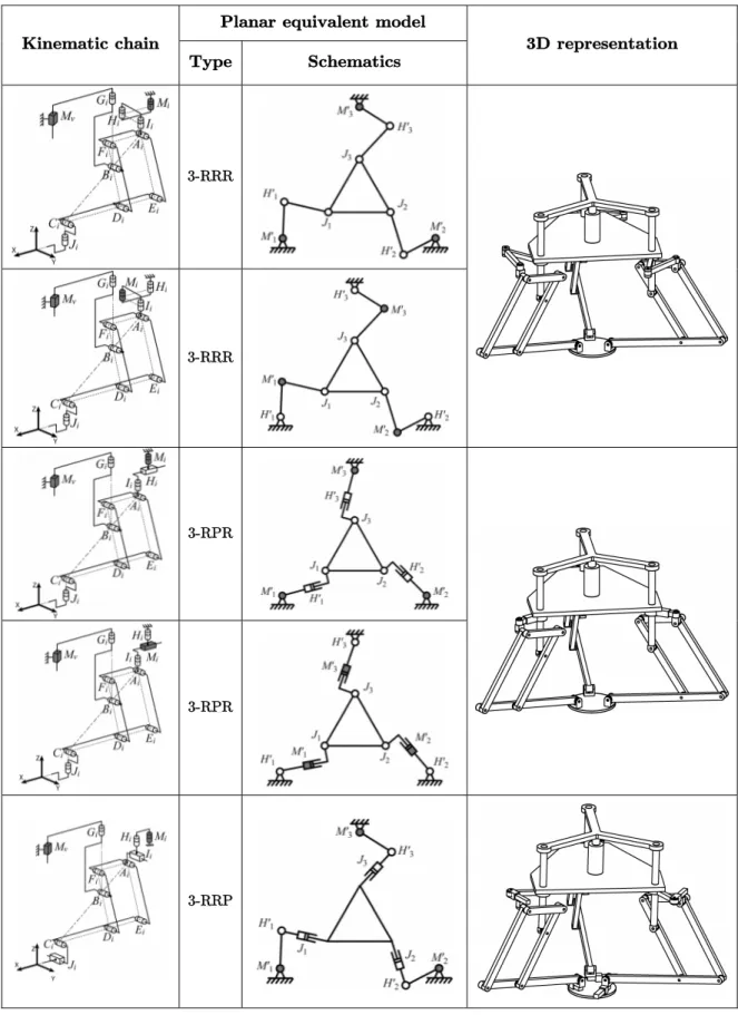
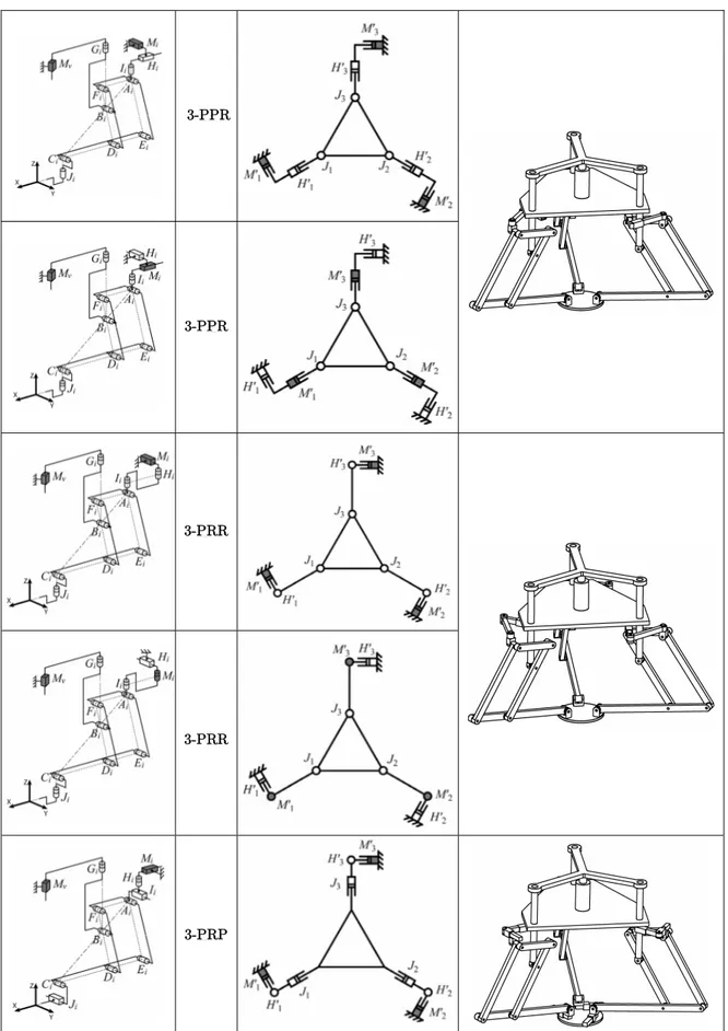
Table 2.1. Examples of motion generation of the input point Ai of pantograph
linkages ...35
Table 2.2. The family of PAMINSA manipulators from 3 to 6 DOF ...38
Table 4.1. Maximum values of the pressure angles (φ = 0°) ...95
Table 4.2. Maximum values of the pressure angles (φ = 45°) ...96
Table 4.3. Total value of singularity-free volumes for each case of actuation ...97
Table 6.1. Dimensions and characteristics of the prototype’s links ... 149
Table 6.2. The poses for the experimental validation of the static balancing .... 162
Table 6.3. The absolute values of the maximal input torques before (case 1) and after (case 2) static balancing...162
Nomenclature
This nomenclature references the principal variables and abbreviations used in this manuscript. The used conventions are the followings:
- vectors and matrices in bold style; - axes names in bold italic style;
- scalar variables and names of points in italic style; - abbreviations of terms in regular style.
A a matrix characterizing the velocity equation of a mechanical system. B a matrix characterizing the velocity equation of a mechanical system. DOF degree(s) of freedom.
g the gravitational acceleration.
i an integer; i = 1, 2, 3.
IBj the inertia matrix of the j-th limb of the pantograph linkage.
Ij the axial moment of inertia of the j-th link of the 5R planar parallel
manipulator.
Ipl the axial moment of inertia of the platform about the z-axis. )
(Bj XX
I the axial moment of inertia about the x-axis of the j-th limb of the pantograph linkage.
) (Bj YY
I the axial moment of inertia about the y-axis of the j-th limb of the pantograph linkage.
) (Bj ZZ
I the axial moment of inertia about the z-axis of the j-th limb of the pantograph linkage.
j an integer.
J the global kinematic Jacobian matrix of a mechanical system.
jDnL references a PAMINSA manipulator with j degrees of freedom and n legs (j = 3 to 6, n = 2, 3).
Nomenclature.
xx
Lj the length of the j-th link of the 5R planar parallel manipulator. li a geometric offset for the design of PAMINSA manipulators. m an integer; m = 0, 1, 2, ...
mBj the mass of the j-th limb of the pantograph linkage.
mj the mass of the j-th axis of the pantograph linkage or of the j-th link of the
5R planar parallel manipulator.
mpl the mass of the platform. n an integer; n = 0, 1, 2, ...
P, P a passive/actuated prismatic joint.
p an integer.
q the vector of the active-joints variables.
qj the j-th active-joint variable for the planar displacements of the PAMINSA
manipulators or for the 5R robot.
qv the active-joint variable for the vertical translations of the PAMINSA-4D3L. qvi the active-joint variable for the vertical translations of points Bi of
pantograph linkages.
R, R a passive/actuated rotoid joint.
Rb the radius of the circumscribed circle of the base triangle.
Ri a wrench applied on the platform by the i-th leg.
rj the relative position of the centers of masses of the j-th limb of the 5R parallel
robot.
Rpl the radius of the circumscribed circle of the platform triangle.
S a passive spherical joint.
T the kinetic energy of a mechanical system. t a twist.
V the potential energy of a mechanical system. W a wrench.
x the position of the platform along the x-axis of the base frame.
x an axis.
x the vector of the coordinates of the platform.
y the position of the platform along the y-axis of the base frame.
y an axis.
z the position of the platform along the z-axis of the base frame.
z an axis.
Nomenclature.
αb an angle characterizing the base triangle. αpl an angle characterizing the platform triangle. βb an angle characterizing the base triangle. βpl an angle characterizing the platform triangle.
δij the Kronecker symbol; δij = 1 if j = i and δij = 0 if j ≠ i δpl an angle; δpl = βpl /2+nπ (n = 0, 1, 2, …).
δx the position error of the platform along the x-axis of the base frame. δx the vector of the errors of the platform.
δy the position error of the platform along the y-axis of the base frame. δz the position error of the platform along the z-axis of the base frame. δφx the orientation error of the platform around the x-axis of the base frame.
δφy the orientation error of the platform around the y-axis of the base frame.
δφz the orientation error of the platform around the z-axis of the base frame. ∆X the norm of the vector of position error due to active-joints errors.
∆φ the orientation error due to active-joints errors.
ε the error bound on the active-joint variables
εi an angle for the kinematic description of the i-th pantograph linkage. εpl an angle; εpl =αpl ±π/2.
φ the orientation of the platform around the z-axis of the base frame.
γi an angle; γi = —5π/6, —π/6, π/2.
λ the vector of the Lagrange multipliers.
θ the orientation of the platform around the z-axis of the second intermediary moving frame (Euler angles description).
ρi the length of the i-th passive prismatic joint of the PAMINSA manipulators.
τ the vector of the actuators torques/efforts.
ψ the orientation of the platform around the x-axis of the first intermediary moving frame (Euler angles description).
Introduction
Context of the thesis.
Over the last decades, researchers and companies have been attracted by the idea of creating new parallel manipulators. Such a mechanical architecture divides the manipulated load between the several legs of the system and, as a result, each kinematic chain carries only a fraction of the total load. Thus, it makes it possible the creation of mechanical structures with higher rigidity, containing movable links having relatively small masses. Many industrial applications of these manipulators in the electronics, food and pharmaceutical sectors, or in aeronautics or medical devices are well-known.
However, parallel manipulators have also some drawbacks, such as a limited workspace, more constraining singularity loci or a high coupling of kinematics and dynamics.
This non-linearity of the kinematic and dynamic models of parallel manipulators is not attractive for industrial applications. In order to solve this problem, over the last few years, new structures have been developed. The literature review of previous research on decoupling of the kinematic and dynamic input/output relationships of parallel manipulators shows that, in most of the cases, two approaches are developed (see chapter 1):
- decoupling between position and orientation;
- full-decoupling, i.e. the decoupling of the displacements in relation to all the degrees of freedom of the platform.
Our observations show that, despite rather encouraging results, it is not easy to develop a simple parallel architecture with fully-decoupled motions whilst conserving its principal advantages: a greater rigidity of the structure with light links.
In order to solve this problem, we have tried to find a compromise between the decoupling of the movements and the architectural characteristics of parallel structures.
Introduction.
2
parallel architecture be fully decoupled, it can also be partially decoupled but it is important to obtain a mechanical architecture with important payload. This problematic has led to the creation of a new family of decoupled parallel manipulators, which is the main topic of this thesis.
Contributions of the thesis.
This manuscript presents several major contributions which are listed below:
- the creation of a new family of decoupled parallel manipulators: the non-linearity of the kinematic and dynamic models of parallel manipulators is not attractive for industrial applications. In order to solve this problem, decoupled structures have been proposed. It appears in chapter 1 that, in order to decouple the kinematic and dynamic input/output relationships of parallel manipulators, two approaches are developed in most of the cases: (i) decoupling between position and orientation; (ii) full-decoupling, i.e. the decoupling of the displacements about all the degrees of freedom of the platform. Despite rather encouraging results, the fully-decoupled manipulators have drawbacks also, such as a lack of rigidity or the increase in the number of joints. This is the reason why we have tried to find a compromise between the decoupling of the movements and the architectural characteristics of parallel structures. In chapter 2, a new design approach is proposed and a family of new parallel manipulators, of which displacements in the horizontal plane are decoupled from the other movements, is developed. These manipulators are called PAMINSA (PArallel Manipulators of the I.N.S.A.); - the singularity analysis of PAMINSA manipulators: one of the most
important drawbacks of parallel manipulators is their singular configurations. Therefore, the chapter 3 analyses the singularities of PAMINSA manipulators. It is shown that one particular case of singularity corresponds to an unusual type of self motion. Thus, the geometric conditions for such a type of self motion are derived and the global behaviour of the manipulators inside the gained degree of freedom is kinematically interpreted. The obtained results can be used to design manipulators without self motions, to optimize the singularity-free workspace of this type of robots and to choose the optimal architectures of PAMINSA manipulators;
Introduction.
- the increase of singularity-free zones by the use of mechanisms of variable structures: the closed-loop of parallel manipulators limits the motion of the platform and creates special singular zones inside the workspace. The workspace of parallel manipulators, which is less than that of serial manipulators, is reduced and limits their functional performances. Therefore, solutions for enlarging the workspace of parallel manipulators are needed. One possible solution consists of using mechanisms with variable structure, i.e. mechanisms of which structure parameters can be altered. This solution is developed in chapter 4. For this purpose, the pressure angle is used as an indicator of force transmission. The optimal control of the pressure angle for a given trajectory of the manipulator is obtained by means of legs with variable structure. The suggested procedure used to determine the optimal structure of PAMINSA manipulators is performed and illustrated by two numerical simulations. Such a solution can be easily extended to other type of parallel structures, such as Gough-Stewart platforms;
- the optimal dynamic conditions for passing through the Type 2 singular configurations: the chapter 5 presents another method, based on the optimization of the dynamic parameters of parallel manipulators, which makes it possible to pass through the Type 2 singular configurations (see chapter 3), and as a result, to enlarge the workspace of parallel mechanisms. The principal contribution of this chapter is the presentation, for the first time, of the general definition of the condition for passing through the singular position which can be formulated as the following: in the presence of Type 2 singular configurations, the platform of a parallel manipulator can pass through the singular positions without perturbation of motion if the wrench applied on the platform by the legs and the external loads is orthogonal to the direction of the uncontrollable motion (in other terms, if the work of applied forces and moments on the platform along the uncontrollable motion is equal to zero). An example of this approach is treated on a PAMINSA manipulator and experimental validations are shown;
- the proposition of a simple method for the accuracy analysis of PAMINSA manipulators: simple and fast methods for computing the accuracy of a given robot design are needed in order to use them in design optimization procedures which seek maximum accuracy. Several performance
Introduction.
4
Therefore, in chapter 6, a simple method for the accuracy analysis of PAMINSA manipulators is presented. This method is achieved by following a detailed mathematical proof that gives important insight into the accuracy of planar parallel robots. The method is illustrated on two practical designs; - the improvement of the performances of PAMINSA manipulators: in
chapter 6, we also propose new compensation schemes, which consist of the introduction into the initial system of complementary units making it possible to cancel the positioning errors. Two different approaches are proposed and the performances of such designs are shown. The reduction of the input torques is also studied. It is shown in simulation and by experimental tests that, for a dynamic mode of operation, the complete static balancing may be ineffective in terms of input torques. In the case of accelerated motions, it is proposed to carry out an optimal redistribution of the movable masses and to achieve a partial mass balancing.
Chapter 1
Parallel Robots: from the Gwinnett
Platform to the Tripteron
1.1. The historical evolution of parallel robots. p. 6 1.2. Towards the kinematic decoupling of parallel structures. p. 16
1.3. Summary. p. 26
This chapter is devoted to the historical evolution of parallel manipulators. First of all, a review of the well-known parallel structures which are applied in industry, patented or prototyped, is presented. The efficiency of such structures is shown and their advantages and drawbacks are discussed.
It is well-known that parallel manipulators have attracted several manufacturers because it was promised, they would have greater rigidity and better dynamic characteristics compared with their serial counterparts. However, despite these very attractive advantages, they also have some drawbacks, as for example, a small workspace, the presence of singular positions and nonlinear coupled kinematics and dynamics. It is obvious that a parallel structure with linear input-output equations is more appealing than a nonlinear one. A literature review shows the principal solutions for motion decoupling of parallel manipulators: (i) decoupling between position and orientation; (ii) full-decoupling, i.e. the decoupling of the displacements around all the degrees of freedom of the platform.
Finally, it is proposed to find a new kind of decoupling, which could be used for the development of new architectures of parallel manipulators with high-load carrying capacity.
Chapter 1: Parallel robots: from the Gwinnett platform to the Tripteron.
6
1.1. The historical evolution of parallel robots.
In this chapter, we propose to make a short presentation of the expansion of parallel structures. However, please note that we do not want to make an exhaustive list of all the existing parallel machines, but to give some key points in the development of these structures.
1.1.1. At the beginnings.
Mechanisms known as parallel manipulators are defined in the terminology for the mechanism and machine science [IFToMM 2003] as manipulators that control the motion of their end-effector by means of at least two kinematic chains going from the end-effector towards the frame.
There exist numerous texts which deal with the true origins of parallel robots, such as [Bonev 2003a] and [Merlet 2006a]. Accordingly to Dr. Bonev, it seems that, the history of parallel kinematic began in 1928 when James E. Gwinnett thought of building a motion platform for the entertainment industry and applied for a patent which presents a device based on a spherical parallel mechanism [Gwinnett 1931] (Fig. 1.1).
Figure 1.1. – Possibly the first spatial parallel mechanism [Gwinnett 1931].
However, the industrial development of parallel structures really began with the development of the Gough platform [Gough 1962]. Dr. Eric Gough is the person who built the first octahedral hexapod, which is probably the most popular parallel robot
1.1. The historical evolution of parallel robots.
(Fig. 1.2). This parallel mechanism was invented in 1947 to respond to problems of aero-landing loads. A universal machine was needed in order to determine the properties of tires under combined loads.
This robot probably has the simplest structure a parallel manipulator can have. It is composed of six legs. Each leg is made of a jack which is connected to both the base and the platform by spherical joints located at the end of each leg. The actuation is achieved by changing the length of the legs.
Figure 1.2. – The first octahedral hexapod [Gough 1962].
The idea of using hexapods for aeronautics appeared only twenty years later when Dr. Stewart described a 6-degrees-of-freedom (DOF) manipulator for use as a flight simulator [Stewart 1965] (Fig. 1.3). In the 1960’s, the expansion of the aeronautic industry, the increasing costs for the training of pilots and the necessity of testing new aircrafts led to the creation of new mechanical structures able to move a platform with a very high payload (which can carry aircraft cockpits for example). The aim of such systems is to create manipulators with high rotational acceleration capacities. For this purpose, hexapods are well suited because they have a high ratio payload/mass-of-the-structure.
Nowadays, thanks to its attractive characteristics, the industrial applications of the Gough-Stewart platform have been diversified (surgical operations, assembling, etc. –
Chapter 1: Parallel robots: from the Gwinnett platform to the Tripteron.
8
Figure 1.3. – The Stewart platform [Stewart 1965].
(a) Fanuc F-100 robot for assembling applications.
(b) Motorized manipulator for surgery. [Lazarevic 1997]
Figure 1.4. – Various applications of the Gough-Stewart platform.
The evolution of parallel manipulators continued with the creation of the Delta robot by Prof. Raymond Clavel in 1986 [Clavel 1990]. The creation of this robot resulted from a simple observation.
During a visit to a chocolate factory, Prof. Clavel noticed that the manual conditioning of the chocolates was a monotone and boring activity for the operators. Moreover, there was a lack of hygiene during the manipulation of the products.
1.1. The historical evolution of parallel robots.
However, he also noticed that the existing industrial robots were not well suited to replacing the operators because of their poor dynamic capabilities which would have resulted in to a poor productivity.
Thus, Prof. Clavel suggested a new original device for positioning and orienting an element in space (Fig. 1.5).
Figure 1.5. – Schematic of the Delta parallel robot from Prof. Clavel’s patent [Clavel 1990].
The displacement of the platform (8) of the Delta robot is the result of the movement of the three articulated arms (4) mounted on the base (1), each of which is connected to a pair of parallel rods (5). The three orientations are eliminated by joining the rods in a common termination and the three parallelograms ensure the stability of the platform (8). This configuration of the robot has three degrees of freedom. The platform (8) stays constantly parallel to the base (1) and cannot rotate about the axis perpendicular to this plane. The platform (8) supports a working element (9) the rotation of which is controlled by a fixed actuator (11) situated on the base (1) by means of the slider (14). Thus, taking into account this supplementary rotation, the Delta robot has four degrees of freedom.
It should be noted that the Delta robot was developed for high-speed manipulations (Fig. 1.6.a) and it is well known in the electronics, food and pharmaceutical sectors as a
Chapter 1: Parallel robots: from the Gwinnett platform to the Tripteron.
10
more attention has been paid to the increasing number of possible industrial applications, such as the manipulation of medical devices (Fig. 1.6.b).
(a) the FlexPicker by ABB. (b) the SurgiScope by ISIS.
Figure 1.6. – Various applications of the Delta robot.
1.1.2. Prototypes and industrial applications of parallel manipulators.
Nowadays, parallel structures are well known and widely developed, mainly for machining applications. While the number of DOF can vary, the actuated systems can be linear or rotary and the number of legs can change, their structures are mostly some declinations of the Gough-Stewart platform and of the Delta robot.
Parallel robots are very attractive for several industrial applications because such mechanical architectures divide the manipulated load between the several legs of the system and, as a result, each kinematic chain carries only a fraction of the total load, which allows the creation of more rigid robots. Such structural architectures also make it possible to reduce the mass of the movable links (all the actuators are mainly fixed on the base and many legs are stressed by traction/compression efforts) and, as a result, make it possible to use less powerful actuators. Moreover, compared with the errors of serial manipulators which are accumulated, it seems the errors of parallel
1.1. The historical evolution of parallel robots.
manipulators are averaged out. Such characteristics promise to create structures with high payload, high dynamic capacities and high accuracy.
These appealing characteristics have attracted the attention of several researchers and companies, and many of them have begun to patent and to build new machines based on parallel structures. Among several examples, we can notice:
- the Variax (Fig. 1.7.a): this machine with 6 DOF, commercialized by Giddings and Lewis, is typically based on an hexapod structure. It has got a large workspace (700 mm × 700 mm × 750 mm). However, the performances of this machine are not equivalent wherever in its workspace;
- the Tricept (Fig. 1.7.b): Neos Robotics has developed a machine tool with 5 DOF based on a serial wrist with two rotary DOF mounted on a tripod which allows one translation and two rotations. The Tricept is mainly used for welding operations and is one of the most successful parallel machines with more than 200 units sold;
- the Sprint Z3 (Fig. 1.7.c): this machine tool, developed by DS Technologies, has 3 DOF (two rotations and one translation) and is mounted on a serial structure with two translatory DOF, one of which can translate along 60 m. Its use is foreseen for the aeronautic industry.
- the double Scara robot (Fig. 1.7.d): probably one of the most popular structures with 4 DOF (with the FlexPicker). It can place components with a precision of 0.005 mm in a workspace around the size of a DIN A6 sheet of paper (150 mm × 105 mm). Its dynamic properties are very appealing (its cycle period for pick-and-place is inferior to 0.5 s);
- the FlexPicker (Fig. 1.6.a): the FlexPicker from ABB, which is an industrial version of the Delta robot with 4 DOF, can produce accelerations and velocities superior to 10 G and 10 m/s respectively (its cycle period is inferior to 0.4 s);
- the Quattro (Fig. 1.7.e): based on the Delta robot concept [Nabat 2005], but having four legs instead of three (the rotation of the end-effector is induced by the shearing of the platform), the Quattro from Adept is specifically designed for high-speed packaging and material handling. Its dynamic properties are better than for the previous manipulators (its cycle period is inferior to 0.25 s).
- the QuickStep (Fig. 1.7.f): the QuickStep (from Krause & Mauser) has been developed for high speed cutting operations. It is a Delta like robot with 3
Chapter 1: Parallel robots: from the Gwinnett platform to the Tripteron.
12
the same plane). Its workspace is quite significant (630 mm × 630 mm × 500 mm) and it can reach velocities about 200 m/min and accelerations superior to 2 G;
- the UraneSX (Fig. 1.7.g): the UraneSX, from Renault Automation, has been designed on the same structure as the QuickStep. It can reach velocities about 150 m/min and accelerations from 3.5 up to 5 G;
- the XYθ stage NAF 3 (Fig. 1.7.h): it is a planar parallel manipulator with 2 translations and one rotation developed by Seiko. This robot has been designed for positioning operations requiring high rigidity and high accuracy in a small workspace (repeatability: 0.7 µm; workspace: 3 × 3 mm for 3 deg. of orientation).
- the Orthoglide (Fig. 1.7.i): this mechanism with 3 translatory DOF was developed at the IRCCyN of Nantes (France) [Chablat 2000] [Chablat 2003]. The use of this robot is foreseen for high-speed machining applications (workspace: 200 mm × 200 mm × 200 mm; velocity of 1.2 m/s and acceleration of 20 m/s2).
- the Schoenflies Motion Generator (SMG – Fig. 1.7.j): the SMG of McGill University (Montreal, Canada) [Angeles 2006] has 3 translatory DOF and one motion of rotation. It is designed for pick-and-place operations. Its cycle period is about 0.5 s.
- the Isoglide (Fig. 1.7.k): this mechanism with 4 DOF [Gogu 2007] (3 translations and one rotation) was developed at the LAMI of Clermont-Ferrand (France). This manipulator is decoupled (see section 1.2.2) and can be used in machining applications where great accuracy is necessary.
- the CaPaMan (Cassino Parallel Manipulator – Fig. 1.7.l): this family of
spatial parallel manipulators with 3 controlled DOF was developed in the LARM of Cassino (Italy) [Ottaviano 2001]. Several prototypes have been completed for different types of applications, such as earthquake simulations. Surprisingly, despite numerous promises of parallel structures, companies such as Giddings & Lewis and Ingersoll with long-standing expertise in machining have failed with their hexapods even though they were the first to deliver them to the market. Why did have they met such a defeat? Were the promises of high payload capacity, high velocities and high accuracy too ambitious?
1.1. The historical evolution of parallel robots.
(a) the Variax by Giddings and Lewis. (b) the Tricept by Neos Robotics.
(c) the Sprint Z3 by DS Technologies. (d) the Scara robot from Mitsubishi.
Chapter 1: Parallel robots: from the Gwinnett platform to the Tripteron.
14
(g) the UraneSX by Renault Automation. (h) the XYθ stage NAF 3 by Seiko.
(i) the Orthoglide of the IRCCyN. (j) the SMG of McGill University.
(k) the Isoglide of the LAMI. (l) the CaPaMan of the LARM.
1.1. The historical evolution of parallel robots.
Indeed, the fact that virtually all the hundreds, or even thousands, of motion simulators with load capacities of up to several tons are based on parallel robots (mostly hexapods), compared with serial robots, which are able to carry at most five hundred kilograms, unquestionably demonstrates that the promise of high payload capacities has been fulfilled. The commercial success of the Delta parallel robot and the performance of the recently launched Quattro confirms the fulfillment of the promise of high productivity, though serial robots are not far behind (Scara serial robots can operate at up to 140 cycles per minute and cheaper linear motors make Cartesian robots operate even faster). But the promise of high accuracy has not been fulfilled yet. Among several factors which may lead to the poor accuracy of these mechanisms, we may note:
- the presence of singularities in the workspace, some of them leading to huge positioning errors (the Type 2 singularities – see chapters 3 and 6); such a problem may however be avoided by the use of actuation redundancy (which is a costly solution) or by reducing the size of the workspace (which is already smaller than for their serial counterparts);
- the use of links with lighter masses which leads to a loss of rigidity of the structure; such a problem may be easily avoided by the use of more rigid links;
- manufacturing errors and joint clearances, which can be rectified by calibration and an appropriate design;
- the non-linearity and the complexity of the kinematic and dynamic models of the parallel manipulators which leads to positioning errors. It seems obvious that if the position (or the orientation) of a manipulator depends on fewer input parameters, it will be less sensitive to input errors.
The non-linearity of the static and dynamic models of parallel manipulators is really not attractive for industrial applications and leads to insurmountable problems of accuracy. This is the reason why, over the last few years, new structures of parallel architectures have been developed in order to simplify and linearize the kinematic and dynamic input/output relationships.
Chapter 1: Parallel robots: from the Gwinnett platform to the Tripteron.
16
1.2. Towards the kinematic decoupling of parallel
structures.
In order to improve the accuracy of the parallel structures, researchers have thought of decoupling/simplifying the control laws of such structures. This is an interesting point of view because:
- decoupling the control laws implies decreasing the number of error parameters able to influence the accuracy of a parallel manipulator;
- decoupling makes it possible to improve the dynamic performances of parallel manipulators because there is no need to synchronize the different actuators. Several approaches of decoupling the control laws have been proposed in the literature. Let us consider these approaches.
1.2.1. From the decoupling between position and orientation...
Designing for decoupled parallel manipulators began when Prof. Clavel developed the 4-DOF Delta robot (Fig. 1.5), of which position is decoupled from its orientation. However, it seems decoupling really started to attract the interest in the 90’s. One of the first works on this subject was proposed in [Patarinski 1993].
In this paper, the authors proposed four new manipulators with 6 DOF derived from the Gough-Stewart platforms, in which the laws controlling the position of the end-effector are decoupled from the laws controlling its orientation (Fig. 1.8). For each of them, three legs control the position P of the moving platform while the orientation is controlled by the actuation of the six legs.
In this article, the authors also present the kinematic analysis of such manipulators. It is shown that their Jacobian matrices (which make it possible to obtain the twist of the platform as a function of the velocities of the articulated joints) have a block triangular structure, which simplifies the kinematic control laws.
The principal drawback of such structures is the necessity of using a triple spherical joint at point P. The use of such a triple spherical joint complicates the design and can create serious technological problems. However, such design conditions are improved in the works [Di Gregorio 2001] and [Legnani 2005].
In 1995, Prof. Min Ki Lee presented a new decoupled structure [Lee 1995] that he named the double parallel manipulator (Fig. 1.9).
1.2. Towards the kinematic decoupling of parallel structures.
(a) basic structure. (b) double tetrahedron.
(c) decoupled parallel manipulator with R1
joints (at Cj, j = 1 to 6).
(d) decoupled parallel manipulator with both P and R joints (at Cj, j = 1, 2, 3).
Figure 1.8. – The decoupled parallel manipulators proposed in [Patarinski 1993].
This manipulator is made up of two parallel manipulators with a common central axis. The first manipulator with three linear actuators places a movable platform-1 at the desired position. In the second manipulator, two linear actuators tilt the platform-2 to the desired orientation with respect to the base-2 which is rigidly located above platform-1. Linear actuators are attached to base-1 and base-2 via universal joints and connected to platform-1 and platform-2 via spherical joints. The purpose of the
Chapter 1: Parallel robots: from the Gwinnett platform to the Tripteron.
18
common central axis is to constrain each parallel manipulator in order to have respectively 3 and 2 DOF. Adding a rotary actuator on platform-2 allows the decoupled parallel manipulator to have 6 DOF.
Figure 1.9. – The double parallel manipulators proposed in [Lee 1995].
The same design approach is applied by Prof. Lallemand in the double-Delta parallel robot [Lallemand 1997]. The first Delta manipulator places a movable platform at the desired position. The second Delta robot makes it possible to orient the end-effector with respect to the base frame.
Obviously, the control laws of such structures are simplified because one manipulator makes it possible to position the end-effector and the other makes it possible to orientate it. However, their major drawback is their design complexity.
1.2. Towards the kinematic decoupling of parallel structures.
In 1995 again, the Nabla 6 was presented in [Bernier 1995]. This manipulator is a spatial robot with 6 DOF actuated by six linear motors (Fig. 1.10). The centre of the platform is linked to the extremity of three rods via a triple spherical joint. The other extremity of each rod is linked via spherical joints to a moving solid (B1, B2 and B3
respectively) which has a linear movement along a linear guide. The three guiding axes lie on a same plane and intersect at point G. The angle between the axes is equal to 120 deg. Three other rods are connected via spherical joints to the platform and to the moving solids (B4, B5 and B6). The orientation of the platform is controlled by the
displacement of the six linear actuators.
Figure 1.10. – Architecture of the Nabla 6.
As for the manipulators of [Patarinski 1993], the Jacobian matrix has a block triangular structure, which simplifies the kinematic control laws.
Three years later, in the study [Mianowski 1998] the Polman-6 (Fig. 1.11) was developed. This manipulator consists of three identical driving mechanisms in the form of 2-DOF five bar planar parallelograms mounted in the base in such a way that their axes are situated in the lines parallel to x, y and z-axes of the Cartesian coordinate system. The moving platform has a form of a half spatial cross with spherical joints and is connected to driving mechanisms by the way of three identical parallelograms similar to those used in the Delta robot. With such a structure, the position of the end-effector is controlled by the rotation of the rods (1), (2) and (3) while the orientation is controlled by the rotation of the rods (4), (5) and (6). This time, the position of the end-effector is totally independent on its position, which implies that the laws are much
Chapter 1: Parallel robots: from the Gwinnett platform to the Tripteron.
20
Figure 1.11. – Architecture of the Polman-6.
All the presented works dealt with the decoupling between the position and the orientation of the parallel manipulators with 6 DOF. However, the robots with 6 DOF are not the only manipulators of which control laws can be simplified. The decoupling between position and orientation can also be obtained on structures with different DOF. As examples, we can notice:
- spatial structures with two translations and one rotation (Fig. 1.12.a): some examples of such structures have been presented in [Chablat 2003]. The position of the point P in the xOy plane is controlled by the displacement of one planar mechanism controlled by prismatic joints of which direction are e1
and e2, and the orientation is given by the displacement of the link B3P which
is actuated through a prismatic joint of which direction is e3.
- spatial structures with two translations and two rotations (Fig. 1.12.b): the example we present for such structures is based on the previous manipulator. While the position is controlled by the displacement of one planar mechanism, the orientations are obtained by the displacement of the link CP. The position of point C is controlled by the simultaneous displacement of linear actuators of which directions are e3 and e4;
- spatial structures with one translation and two rotations (Fig. 1.12.c, d, e): presented in [Jin 2004], it is specified that, for all these manipulators, the position (S2/R2) is controlled by the displacement of one leg and the
1.2. Towards the kinematic decoupling of parallel structures.
(a) (b)
(c) (d)
(e) (f)
Chapter 1: Parallel robots: from the Gwinnett platform to the Tripteron.
22
- planar structures with three translations and one rotation (Fig. 1.12.f): for this manipulator presented in [Yu 2006], the displacement along the x-axis is fully independent. The translation along the y-axis is allowed by the simultaneous displacements of the prismatic pairs ρ2 and ρ3 and the orientation is obtained
by their antagonistic displacements.
It should be noted that the decoupling between position and orientation is not the only case of partial decoupling of parallel structures. There are also other kinds of simplification of the control laws, as for example the partial decoupling between the DOF of manipulators with only translatory movements (Fig. 1.13). For the presented mechanism, the translation along the x-axis is decoupled from the translations along the other axes.
Thus, the control laws of the manipulators of which positions are decoupled from their orientations have evolved in order to be dependent on fewer parameters, and, as a result, to become simpler. However, even if the simplification is already tangible, the kinematics relationships are still coupled. Therefore, researchers have continued to seek architectures with the simplest control law possible.
Figure 1.13. – Other kind of partial decoupling [Jin 2004].
1.2.2. ... to the full-decoupling of the movements.
The next step of the simplification of the control laws of the manipulators is the apparition of fully-isotropic manipulators.
Isotropicity of a robotic manipulator is related to the condition number of its Jacobian matrix, which can be calculated as the ratio of the largest and smallest singular value. A robotic manipulator is fully-isotropic if its Jacobian matrix is isotropic
1.2. Towards the kinematic decoupling of parallel structures.
throughout the entire workspace, i.e. the condition number of the Jacobian matrix is equal to one. The condition number is an interesting index characterizing the distortion of a unit hypersphere under the linear mapping [Angeles 2003]. It has been developed as a kinetostatic performance index of robotic mechanical systems [Merlet 2006b]. Thus, the isotropic design aims at ideal kinematic and dynamic performance of the manipulator [Fattah 2002].
Several works have dealt with the synthesis of fully-isotropic parallel manipulators [Bouzgarrou 2004] [Carricato 2002] [Carricato 2004a] [Carricato 2004b] [Gogu 2004] [Gogu 2005a] [Gogu 2005b] [Gogu 2005c] [Gogu 2005d] [Gogu 2006a] [Gogu 2006b] [Gogu 2006c] [Gogu 2007] [Gosselin 2004] [Gosselin 2007] [Kong 2002a] [Kong 2002b] [Li 2004] [Richard 2007]. An analysis of these works shows that the Jacobian matrix J of such structures mostly corresponds to the identity matrix. Thus the kinematic control laws are very simple:
q V & = ⎥ ⎦ ⎤ ⎢ ⎣ ⎡ ω (1.1)
where V corresponds to the Cartesian velocity of the platform, ω to its rotational velocity and q& is the vector of the articular velocities. Thus these architectures are fully-decoupled, i.e. the displacements around all the degrees of freedom of the platform are decoupled.
The figure 1.14 presents several examples of fully-isotropic manipulators. The manipulator of figure 1.14.a is a manipulator with one translation and two rotations. The translational displacement of the end-effector along the x-axis is directly obtained by the movement of the prismatic pair (2A). One rotation of the platform is performed
by the displacement of one rotating actuator (2B) and the rotation about the other axis
is given by the displacement of a second rotating actuator (2C).
Figure 1.14.b presents a manipulator with two translations and two rotations. The laws controlling the position and orientation of the end-effector are fully-decoupled, i.e. the displacement of the controlled point along the x and z-axes are respectively obtained by the actuation of the prismatic guides (2A) and (2B) and the two
orientations of the platform are obtained by the rotation of actuators (2C) and (2D)
respectively.
The architecture of figure 1.14.c represents a fully-isotropic manipulator with 3 translations and 1 rotation. Once again, the position and orientation of the end-effector
Chapter 1: Parallel robots: from the Gwinnett platform to the Tripteron.
24
axes are respectively obtained by the actuation of the prismatic guides (2A), (2B) and
(2C) and the rotation of the platform is given by the rotation of link (2D). The same
design concept is proposed in the manipulator of figure 1.14.d.
(a) 1 translation and 2 rotations. (b) 2 translations and 2 rotations.
(c) 3 translations and 1 rotation. (d) 3 translations and 1 rotation.
1.2. Towards the kinematic decoupling of parallel structures.
It may be mentioned that many works on full-decoupling of the movements deal with manipulators with translatory motions. Such a result has been obtained in publications as [Carricato 2002] [Carricato 2004b] [Gosselin 2004] [Kong 2002a] [Kong 2002b] [Li 2004]. Some examples of such structures are presented in figure 1.15. For all these manipulators, it is possible to see that the displacement of only one actuator controls the translation of the platform along one direction.
(a) (b)
(c) (d) Figure 1.15. – Examples of fully-decoupled manipulators with 3 translatory DOF:
(a) and (b), two manipulators designed in [Carricato 2004b], (c) and (d), two possible arrangements of manipulators called Tripteron presented in [Gosselin 2004]
Chapter 1: Parallel robots: from the Gwinnett platform to the Tripteron.
26
Obviously, the most important advantage of such fully-decoupled manipulators is their very simple input/output kinematic relationships (and as a result their input/output dynamic equations).
However, despite these very encouraging results, fully-decoupled structures have also many drawbacks, such as:
- the increase in the number of joints, which multiplies the number of parameters which can induce errors during the manufacturing stage;
- the loss of rigidity of the structures; on figures 1.15.a, b and d, one can see that the payload is only supported by one leg. This is in contradiction with one of the main advantages of the parallel manipulators (each kinematic chain carries only a fraction of the total load, which leads to the creation of more rigid robots).
It seems obvious that trying to simplify the control laws of parallel structures and conserving their principal advantages is a complicated problem. This is the reason why we have tried to find a compromise between the decoupling of the movements and the architectural characteristics of the parallel structures, i.e. to find a new kind of decoupling which makes it possible to develop parallel manipulators with high-load carrying capacities.
1.3. Summary.
In this chapter, we have presented a short review of the well known parallel structures which were patented and developed for industry. Parallel manipulators have attracted several manufacturers because it was promised, they would have greater rigidity, better velocities and dynamic characteristics and greater accuracy compared with their serial counterparts. However, despite these very attractive advantages, companies have mostly failed to deliver parallel structures to the market.
While the promises of great rigidity and high velocities have already been obtained on several structures, the promise of a high degree of accuracy has not been fulfilled yet, which can explain the industrial defeat of parallel manipulators.
Among several factors which may lead to the poor accuracy of the mechanisms, we may note:
- the presence of singularities in the workspace, some of them leading to huge positioning errors; however, solutions have already been proposed and validated;
1.3. Summary.
- the use of links with lighter masses which leads to a loss of rigidity of the structure; such a problem may be easily avoided by the use of more rigid links; - manufacturing errors and joint clearances, which can be rectified by calibration
and an appropriate design;
- the non-linearity of the kinematic and dynamic models of the parallel manipulators which leads to tracking errors.
In order to solve the problem of the poor accuracy of the parallel structures, several researchers have thought of decoupling/simplifying the control laws of such structures. Our literature review shows that, in most of the cases, two approaches are developed:
- decoupling between position and orientation;
- full-decoupling, i.e. the decoupling of the displacements around all the degrees of freedom of the platform.
Despite these rather encouraging results, the fully-decoupled manipulators have drawbacks also, such as a lack of rigidity or the increase in the number of joint.
In the following chapter, a new approach to the decoupling of parallel structures is presented. This approach seeks to find a compromise between the decoupling of the movements and the architectural characteristics of the parallel structures.
Chapter 2
PAMINSA: A New Family of Decoupled
Parallel Manipulators
2.1.
Design analysis of PAMINSA manipulators. p. 30
2.2. Static analysis of the PAMINSA structures. p. 42
2.3. Design of a prototype and experimental validations. p. 45
2.4. Summary. p. 55
In this chapter, a new family of decoupled parallel manipulators is presented. These manipulators are called PAMINSA (PArallel Manipulator of the I.N.S.A.). The characteristic of these manipulators is the decoupling of the displacements in the horizontal plane from the displacements along/about the other directions. Their conceptual design, in which the copying properties of pantograph linkage are used, makes it possible to obtain a large payload capability.
Based on these considerations, parallel structures with 4 DOF are firstly synthesized and a systematic approach for motion generation of input point of each limb is presented. It is then shown that this approach can be extended to manipulators from 3 to 6 DOF.
A basic structure with 4 DOF is studied in order to analytically demonstrate the design concept.
A prototype of PAMINSA manipulator is presented and, then, the experimental validation of the design concept is carried out. It is shown experimentally that the static loads on the rotating actuators, which move the platform in the horizontal plane, are cancelled.
![Figure 1.5. – Schematic of the Delta parallel robot from Prof. Clavel’s patent [Clavel 1990]](https://thumb-eu.123doks.com/thumbv2/123doknet/7792175.260063/34.892.331.590.333.667/figure-schematic-delta-parallel-robot-clavel-patent-clavel.webp)
![Figure 1.9. – The double parallel manipulators proposed in [Lee 1995].](https://thumb-eu.123doks.com/thumbv2/123doknet/7792175.260063/43.892.288.604.285.837/figure-double-parallel-manipulators-proposed-lee.webp)