HAL Id: tel-01232187
https://tel.archives-ouvertes.fr/tel-01232187
Submitted on 23 Nov 2015
HAL is a multi-disciplinary open access archive for the deposit and dissemination of sci-entific research documents, whether they are pub-lished or not. The documents may come from teaching and research institutions in France or abroad, or from public or private research centers.
L’archive ouverte pluridisciplinaire HAL, est destinée au dépôt et à la diffusion de documents scientifiques de niveau recherche, publiés ou non, émanant des établissements d’enseignement et de recherche français ou étrangers, des laboratoires publics ou privés.
Oxide and composite electron transport layers for
efficient dye-sensitized solar cells
Yuly Kusumawati
To cite this version:
Yuly Kusumawati. Oxide and composite electron transport layers for efficient dye-sensitized solar cells. Inorganic chemistry. Université Pierre et Marie Curie - Paris VI; Institut teknologi Bandung, 2015. English. �NNT : 2015PA066240�. �tel-01232187�
Université Pierre et Marie Curie
Insitut Teknologi Bandung
Ecole doctorale chimie physique et analytique (ED 388)
OXIDE AND COMPOSITE ELECTRON TRANSPORT LAYERS
FOR EFFICIENT DYE-SENSITIZED SOLAR CELLS
par
Yuly KUSUMAWATI
Thése de doctorat
Prèsentee et soutenue publiquement le 10 Juin 2015
Devant un jury compose de:
Dr. Thierry Pauportè Directeur de Recherche-CNRS Directeur de thèse Dr. M. A. Martoprawiro Professeur – ITB Co-directeur de these Prof. Fabrice Goubard Professeur Université Cergy-Pontoise Rapporteur
Prof. Gilles Wallez Professeur – UPMC Examinateur
Dr. Samir Farhat Maître de Conférérence – Université Paris XIII
Examinateur
Prof. Dr. Ir. Akhmad Herman Yuwono, M.Phil.Eng
Professeur – UI Rapporteur
ACKNOWLEDGEMENT
It would not have been possible to write this doctoral thesis without the help and support of the kind people around me to only some of them it is possible to give particular mention here.
I would like to express the deepest appreciation to my supervisor in France, Dr. Thierry Pauporté, for his guidance and advice during finishing the research and writing publications in France, also for his patience to correct my thesis.
I would also like to express my sincere gratitude to my supervisors in ITB Dr. M. A. Martoprawiro, Prof. Dr. Ing. Cynthia L. Radiman and Dr. Bambang Prijamboedi. Without them I cannot pass the tricky administration that let the student to graduate. There are no words to exprees my grateful to Prof. Dr. Ing. Cynthia L. Radiman’s patience. I would also like to thank Dr. Bambang Prijamboedi for the intense discussion and for correcting my draft.
Dr. Samir Farhat and Prof. Noureddin Jouni from Laboratoire des Sciences des
Procédés et des Matériaux, LSPM UPR 3407, Université Paris 13, Villetaneuse, France, are
acknowledged for providing ZnO nanorod-like particles and Dr. Cèline Olivier from Institut
des Sciences moléculaires, Université de Bordeaux, France is acknowledged for providing
carbazole dye sensitizer.
I would like to acknowledge Prof. Dr. Djulia Onggo, the head of doctoral school chemistry, ITB, for her time and her effort in manage the academic and administration requirement. I would also like to acknowledge Prof. Dr. Ir. Triyogi Yuwono, the rector ITS (Institut Teknologi Sepuluh Nopember), Prof. Dr. Perry Burhan (Dean of Mathematics and Natural Science Faculty, ITS) and Hamzah Fansury, Ph.D (Head of Chemistry Departement, ITS), who have gave me the permission to take a study.
I would like to acknowledge the financial support from Campus France and the Higher Education Ministry of Indonesian (DIKTI) government in the framework of the DDIP collaboration program. I would also like to acknowledge Prof. Fida Madayanti Warganegara and Mrs. Tri for their effort to manage the program and DDIP’s students, including me.
In addition, of course I would like to thank to all my friends in MPOE, Chimie-Paristech. Thank you Mongia for the dinner in your home, thank you Alexandra for keeping your finger crossed for me, thanks also to Jie, Ricardo, Xue, Frederic, Dora and Sana. Special
thank to all my friends the DDIP scholarship holder and my friends in computational chemistry group ITB. Big thank is addressed to Atthar for helping the calculation and Hasan for keeping the HPC work well. The last, there are no words that can describe the support of my family, my husband, my mother, my father, my sisters and my daughter.
ABSTRACT
OXIDE AND COMPOSITE ELECTRON TRANSPORT LAYERS FOR EFFICIENT DYE-SENSITIZED SOLAR CELLS
Dye-sensitized solar cell (DSSC) is built with combining many components in order to convert the solar energy to electricity. One of the DSSC components is a metal oxide semiconductor which plays the role of electron transport layer (ETL). It receives electrons from photoexcited dyes attached on its surface and ensures the electron transfer to the back contact of the solar cell. Developing the metal oxide that fulfills the requirements as an ETL is one of the effort to increase the DSSC power conversion efficiency. Three kinds of ETL have been developed and studied in this present work as a photoelectrode in DSSC. Those composed of (1) two kinds of TiO2-brookite nanoparticles, (TiO2_B1 and TiO2_B2), (2) the
composite of anatase and graphene (TiO2_Gr) and (3) the nanorods like ZnO nanoparticles
(ZnO_NR), respectively. All photoelectrode are prepared by doctor blading technique. The morphology of photoelectrodes have been characterized using transmission electron microscopy (TEM) and scanning electron microscopy (SEM). The layer thicknesses were measured using profilometry. For the film structural characterizations, a high-resolution X-ray diffractometer was used. The Fourier transform infrared (FTIR) and micro Raman measurement have been carried out to verify the TiO2_Gr composite preparation. The optical
film properties (total transmission and total reflection) were recorded with a spectrophotometer equipped with an integrating sphere techniques. The cell performances were obtained by measuring the I-V curves of the cells undr calibrated illumination. To achieve an in-deep understanding of the cell functioning, the impedance spectroscopy (IS) technique has been studied over a large applied potential range. By doing IS study, the electronic structure, charge carrier lifetime (n), transport/collection time (tr) and electron
transport parameters of the layers have been determined.
The IS study of brookite-based photoelectrode has revealed that, compared to anatase, the brookite surface is less active for the recombination side reaction. A large charge transfer resistance, Rct, is shown which explains the high open circuit voltage of the brookite cells.
However, the charge transport is much slower in the brookite phase due to a lower electrical conductivity. The computational study that has been performed, are in excellent agreement with the experimental results.
The incorporation of 1.2 wt% of graphene into TiO2photoelectrode led to an increase
in conductivity by 60%. This increase induced a faster electron transport in photoelectrode. Moreover, the addition of graphene provoked the improvement in sensitized-layer sensitization and light absorbance. Both improvements resulted in a Jsc enlargement which is promising to apply in cobalt-based DSSCs. The composite of anatase and graphene, TiO2_Gr12 photoelectrode, that was sensitized by the Z907 and was coupled with
[Co(phen)3]2+/3+, showed better cell performance compared to that the one coupled with I3-/I
-redox couple. This cell had performances comparable to the TiO2_A (as reference cell
composed of pure anatase) photoelectrode that was sensitized using the Z907 and was coupled with I3-/I-. The ZnO_NR showed good cell performances. D149 sensitized ZnO_NR cell
coupled with I3-/I-redox-couple had Power Conversion Efficiency (PCE) of 4.82%. The TG6
sensitized ZnO-NR cell showed the best ZnO-based DSSC performances and reached a PCE of 5.3%. We observed that, the outstanding properties of ZnO_NR lie in their large pores size that facilitates more dye to attach to their surface upon the sensitization process. Their advantages then become an interesting point to apply this photoelectrode in cobalt-based DSSC. The cobalt redox-couple species have bulky structures, they need large pores in order to transport through the photoelectrode. Our test employing carbazole dyes as the sensitizer revealed that the ZnO_NR photoelectrode has good performances with cobalt-based redox-couple compared to that triiodide/iodide one. The computational studies have been carried out to investigate the electronic properties of utilized dye sensitizers which are important to support the cell performances explanation.
Briefly, all ETLs that have been developed in the present work have promising properties to be applied as photoelectrode in DSSC. The carefully study of their properties has revealed not only their advantages but also their limitation. This information will be beneficial as a consideration for the future work.
Keywords: Dye-sensitized solar cell, electron transport layer, photoelectrode, TiO2, ZnO, graphene, impedance spectroscopy
Table of Contents
ACKNOWLEDGEMENT ... i
ABSTRACT ... iv
Table of Contents ... vii
List of Figures ...viiii
List of Tables... xiix
List of Appendix... xiii
List of the Important Abbreviations and Symbols ... iv
Chapter I: Introduction ... 1
I.1. Background ... 1
I.1.1. Solar Energy as an Alternative of Renewable Energy... 1
I.1.2. Dye-sensitized solar cells: towards iodine free devices... 3
I.2. Objectives ... 6
I.3. Research Approach ... 6
1.3.1. TiO2Brookite Based DSSC ……… ... 6
1.3.2. TiO2/graphene Based DSSC………... 7
1.3.3. ZnO_NR Based DSSC.. ... 7
1.4. Thesis Organization... 7
References ... 9
Web References: ... 10
Chapter II: Literature Review... 11
II. 1. Fundamental of DSSC ... 11
II. 1.1. DSSC Component... 11
II. 1.2. Electron Transport in DSSC ... 27
II.1.3 Basic Principle in Cell Characterization... 34
II.2 Theoretical Background in Computational Methods... 40
II.2.1 Quantum Chemistry... 40
II.2.2 Density Functional Theory ... 42
II.2.3 Models in Computational Chemistry... 44
II.2.5 TDDFT ... 50
References ... 51
Chapter III: Research Methods ... 60
III.1. Synthesis of particles for the photoanodes ... 61
III. 2. Cell Preparation... 63
III.3. Characterizations ... 68
References ... 70
Chapter IV: TiO2-Based DSSC I: Comparison of Anatase and Brookite-Based Dye-Sensitized Solar Cells... 72
IV. 1. Introduction ... 72
IV.2 Characteristics of the particles ... 72
IV. 3. Cell Performance and Impedance Study ... 76
IV.3.1. I-V Measurement Result ... 76
IV.3.2 Analysis of the open circuit voltage... 78
IV.3.3. Analysis of charge transport and recombination in the photoelectrodes ... 82
IV.4 Computational Study: Comparison of adsorption of Iodine (I2) on Anatase (101) and Brookite (210) planes ... 86
IV. 5 SUMMARY ... 93
References ... 94
Chapter V: TiO2-Based DSSC II: The Effect of Graphene Incorporation in TiO2/graphene for Photoelectrode ... 96
V. 1. Introduction ... 96
V.2 Composite TiO2/Graphene (TiO2_Gr) Preparation ... 99
V.3 The cell performance of TiO2/Gr in iodine based DSSCs: The investigation of graphene’s role in TiO2photoelectrode... 105
V.4 The cell performance of TiO2/Gr in cobalt based DSSC ... 115
V. 5 SUMMARY ... 122
References ... 123
Chapter VI: ZnO Nanorod Based Electron Transport Layer for DSSC... 127
VI. 1. Introduction ... 127
VI. 2. Particle Characterization ZnO_NR ... 129
VI. 3. Utilization ZnO_NR for the comparison of the performance of an organic and an inorganic sensitizer... 131
IV. 4. Impedance Study D149- and TG6-sensitized ZnO_NR cell... 133
IV. 5. Computational investigation of the electronic and optical properties in D149 and TG6 dyes ... 138
VI. 6. Use of photoelectrode ZnO_NR for iodine free DSSC... 142
VI. 7. Computational investigation of the electronic and optical properties of SD4, JM131 and JM164 dyes... 150
VI.8 SUMMARY ... 157
References ... 157
Chapter VII: General Conclusions and Suggestions for Future Works ... 160
List of Publications, Seminars and Workshop ... 164
List of Figures
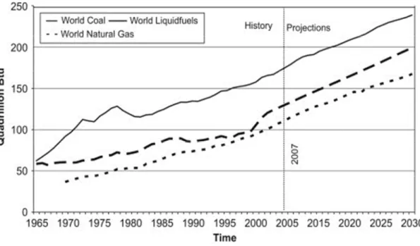
Figure 1.1: Consumption of the fossil fuel in the world from 1965 to 2030 ...1
Figure 1.2: Average annual global solar radiation... 2
Figure 1.3: Some applications of solar cells ... 3
Figure 1.4: Total installed PVs capacity in the world... 4
Figure 1.5: Number of papers on DSSC published since their discovery... 5
Figure 1.6: Two DSSC panels installations in Switzerland. ...5
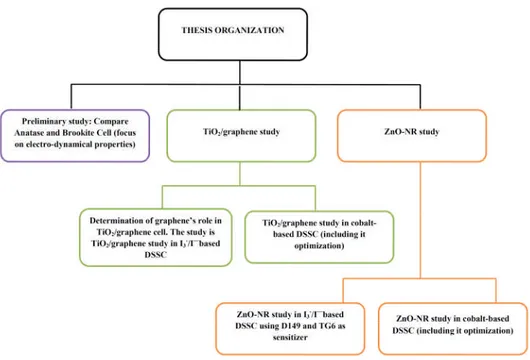
Figure 1.7: Thesis organization ...9
Figure 2.1: Schematic diagram of DSSC using I3 -/I-redox-couple ...12
Figure 2.2: Molecular structures of the dyes, popular in the DSSC literature. ...13
Figure 2.3: D-π-A systems in organic sensitizer SD1... 14
Figure 2.4: Normalized dye absorbance of individual D131, D149 and D205 dyes and of equimolar dye mixtures... 16
Figure 2.5: J–V curves and IPCE curves of ZnO DSSCs sensitized with D131, D149 and D131/D149 ... 16
Figure 2.6: Energy diagram schematic of insulator, semiconductor and metal ...20
Figure 2.7: Energy diagram of several semiconductors together with potential redox of several redox-couples ... 21
Figure 2.8: Crystal structure of rutile, anatase and brookite... 22
Figure 2.9: Wurtzite ZnO crystal stucture, consisting of a ( 2x2x2) unit cell. ...24
Figure 2.10: Simulation of optical absorption of N749 dye attached on TiO2surface ...29
Figure 2.11: Various traps location in the semiconductor. ... 30
Figure 2.12: I-V curves of a cell A with FF = 0.46; and a cell B with FF = 0.67. P-V curve of cell B ... 35
Figure 2.13: Air Mass calculation ...36
Figures 2.14: Typical Nyquist plot of electro impedance spectra ...37
Figure 2.15: Electrical equivalent circuit of typical DSSC... 38
Figure 2.16: Examples of a unit cell for calculations using periodic boundary conditions for system x that contains one unit cell, a crystal surface that has a high lattice parameter in one of direction and a supercell ...47
Figure 2.17: All electron (AE) and pseudopotential (PP) wave functions for Au at l=2. rcis the radius cuttoff in a. u... 48
Figure 3.1: Hydrothermal reactor used for TiO2nanopartciles preparation. ...62
Figure 3.2: Ultrasonic horn to prepare TiO2and ZnO paste... 63
Figure 3.3: Scheme of doctor blade technique layer deposition ... 65
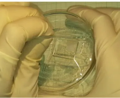
Figure 3.5: Scheme of sealed cell cross-section and picutre of sealed cell that has been
prepared... 67
Figure 4.1: TEM images of particle B1 and B2 ...73
Figure 4.2: Size distribution of the brookite nanoparticles B1 and B2... 73
Figure 4.3: XRD pattern of B1; B2 and Brookite standard ...74
Figure 4.4: XRD patterns of Dyesol and Anatase standard ...74
Figure 4.5: Absorbance spectra of sensitized layer of Dyesol; B1; B2 with immersion time 24 hours and Dyesol with immersion time 4 hours ...75
Figure 4.6: I-V curves of TiO2_B1, TiO2_B2 and TiO2_D under 100 mW.cm -2 , AM 1.5G filtered illumination... 77
Figure 4.7: IPCE action spectra of brookite TiO2_B1 and TiO2_B2 solar cells and of the TiO2_D reference cell. ...77
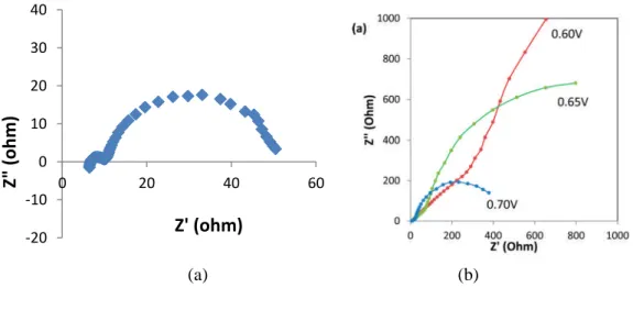
Figure 4.8: Typical impedance spectra in the dark of of B1 brookite cell polarized at 0.775 and effect of applied voltage on the impedance spectra of TiO2_B1 solar cell in the dark. ...79
Figure 4.9: Variation of C with Vcor for TiO2_B1 and TiO2_B2 brookite solar cells and TiO2_D anatase solar cells. ...79
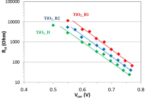
Figure 4.10: Variation of Rctwith Vcorfor TiO2_B1, TiO2_B2 and TiO2_D solar cells... 81
Figure 4.11: Plot of Rct versus Vecb, TiO2_B1, TiO2_B2 and TiO2_D, the applied voltage corrected of the shift due to different conduction band energy level ... 82
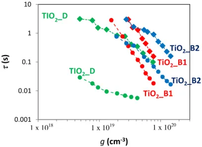
Figure 4.12: Effect of the phase and particle size on the charge carrier lifetimen andtr versus ࢍ... 83
Figure 4.13: Effect of photoelectrode TiO2 crystal phase on Rtr as a function of the corrected applied voltage, TiO2_B1, TiO2_B2 and TiO2_D ... 83
Figure 4.14: Effect of photoelectrode TiO2crystal phase on the charge collection efficiency ...84
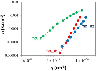
Figure 4.15: Effect of photoelectrode TiO2 crystal phase on the electronic conductivity as a function of the electron concentration,ࢍ. ...85
Figure 4.16: Effect of photoelectrode TiO2crystal phase on Dnparameter ...85
Figure 4.17: Mean diffusion length of electrons, Ln, in mesoporous brookite TiO2 films measured by IS. ... 86
Figure 4.18: Optimized geometry of adsorbed iodine on anatase and brookite surface ... 88
Figure 4.19: DOS of bare anatase (101) bare brookite (210) ...90
Figure 4.20: LDOS of Ti-61, Ti-85, Ti-2 and Ti-62 on anatase ...90
Figure 4.21: PDOS of anatase/I2and brookite/I2... 91
Figure 4.22: The LDOS of Ti-61 3d and I-97 5p in anatase/I2system, LDOS of Ti-82 Ti 3d and I-97 5p in brookite/I2system ...91
Figure 5.1: The Schemes of the carbon allotrope; Graphene, fullerene carbon nanotube, graphite... 96
Figure 5.2: FTIR Spectra of SGO, ethycellulose, TiO2_Gr before heat treatment, TiO2_Gr after heat treatment, TiO2_A after heat treatment ... 100
Figure 5.3: Zoom out of FTIR Spectra of TiO2_Gr after heat treatment and TiO2_A after heat treatment from 950 to 1150 cm-1...100
Figure 5.6: X-ray difractogram of TiO2_A and TiO2_Gr12 ...103
Figure 5.7: BET Isotherm curve ...103
Figure 5.8: Transmission spectra of TiO2_A, TiO2_Gr06, TiO2_Gr12 and TiO2_Gr30 ...104
Figure 5.9: Absorbance spectra of N719 sensitized on TiO2_A, TiO2_Gr06 and TiO2_Gr12 ...105
Figure 5.10: Dark current of FTO without TiCl4treatment, one, two and three preliminary TiCl4 treatment ...106
Figure 5.11: IV-curves of various times TiCl4treatment once, twice and three times ...106
Figure 5.12: I-V curves of TiO2_A, TiO2_Gr06, TiO2_Gr12, TiO2_Gr30 ... 107
Figure 5.13: The I-V parameters plot as function of SGO content:, Jsc, Vocand FF ...108
Figure 5.16: IS Spectra of TiO2_A and TiO2_Gr12 at Vocand TiO2at 0.75 V ...109
Figure 5.17: Variation of Rct and Cwith the corrected applied voltage. ... 110
Figure 5.18: DOS distribution of TiO2_A cell and TiO2_Gr12 ...111
Figure 5.19: Variation of n and tr with the corrected applied voltage of TiO2_A and TiO2_Gr12 cell 112 Figure 5.20: Effect of graphene on the variation of Dnwith the corrected applied voltage ...112
Figure 5.21: Effect of graphene on the variation of Lnwith the corrected applied voltage ...113
Figure 5.22: Effect of graphene on layer conductivity as function ofࢍ ...114
Figure: 5.23 Effect of graphene oncoll...114
Figure 5.24: IPCE spectra of TiO2_A and TiO2_Gr12 ...115
Figure 5.25: Optimized struture of Z907and N719 ...116
Figure 5.26: The effect of thickness on cell performance of cells using electrolyte Co-2 ... 118
Figure 5.27: The effect of TBP concentration on Voc, Jsc, FF and ...119
Figure 5.28: I-V curves of Z907 sensitized solar cells of TiO2_A-iodine, TiO2_Gr12-iodine, TiO2_A-cobalt, TiO2_Gr12-cobalt ... 120
Figure 5.29: Absorbance of Z907-sensitized TiO2_A and TiO2_Gr12 layer... 121
Figure 5.30: IPCE spectra of Z907 sensitized cell TiO2_A and TiO2_Gr12 coupled with I3 -/I-; and TiO2_A and TiO2_Gr12 couple with Co 2+/3+ ...122
Figure 6.1: Various one-dimensional structures of ZnO ... 128
Figure 6.2: Structure of (branched-ZnO-NW and ZnO nano-forest ... 129
Figure 6.3: TEM image of ZnO_NR nanopartciles and SEM image of ZnO_NR layer ...130
Figure 6.4: Particles size distirbution of ZnO_NR ...130
Figure 6.5: XRD pattern of NR partcile based ZnO layer after heat treatment ... 131
Figure 6.6: I-V curves of ZnO_NR sensitized with TG6 and D149. ...132
Figure 6.7: Absorbance spectra of D149 and TG6 sensitized layer of ZnO_NR ...133
Figure 6.8: Typical IS spectra measured in the dark of ZnO_NR_TG6 cell at various appllied potential... 133
Figure 6.9: Variation of Rctof ZnO_NR_D149 and ZnO_NR_TG6 with Vcor ...134
Figure 6.10: Variation of Cof ZnO_NR_D149 and ZnO_NR_TG6 with Vcor...134
Figure 6.11: The logarithmic plots of tr and n of ZnO_NR_D149 and ZnO_NR_TG6 as a function of g ...135
Figure 6.12: The variation of charge collection efficiency (coll) of ZnO_D149 and ZnO_TG6 with Vcor...136
Figure 6.13: The variation of with g of ZnO_NR_D149, ZnO_NR_TG6, TiO2_D, TiO2_B1, TiO2_B2, TiO2_A and TiO2_Gr12 ...136 Figure 6.14: Variation of Dnwith݃ of ZnO_NR_D149, ZnO_NR_TG6 and TiO2_A ...137 Figure 6.15: Variation of Lnwith ݃ of ZnO_NR_D149, ZnO_NR_TG6 and TiO2_A ... 137 Figure 6.16: Calculation and experimental results of UV-Vis spectra of D149 in DMF and TG6
in CH2Cl2...138 Figure 6.17: HOMO and LUMO orbitals of D149 dye. ...140 Figure 6.18: HOMO and LUMO orbitals of TG6 dye... 140 Figure 6.19: Energy diagram of the D149 and TG6 dye orbitals, active in the charge transfer,
conduction band (CB) and valence band (VB) of ZnO and I3
-/ I- redox couple ...141 Figure 6.20: Position of anchoring site (carboxylate function) on the dye D149 and TG6 ...142 Figure 6.21: Structue of SD4, JM131 and JM164 ...142 Figure 6.22: The position of E0of I3
-/I-, [Co(bpy)3] 2+/3+ , [Co(phen)3] 2+/3+ and [Co(bpy-pz)2] 2+/3+ redox-couples ... 144 Figure 6.23: I-V curve of the best ZnO_NR-based cells using [Co(bpy-pz)2]
2+/3+
and I3
-/I- as redox couple with JM164 as senstizer and has ~ 5 µm photoelctrode thickness. ...147 Figure 6.24: The ZnO_NR cell stability of I-V parameters (a) JSC(b) Voc (c) FF and (d). The
cell use [Co(bpy-pz)2] 2+/3+
as redox-couple and JM164 as sensitizer ... 148 Figure 6.25: TEM Image of ZnO_C20 ...149 Figure 6.26: Absorbance spectra a of JM164 in UV-Vis range based on experimental
measurement and on calculation using TD-DFT method and level theory B3LYP, b97XD and CAM-B3LYP... 151 Figure 6.27: Calculation and experimental results of absorbance spectra in UV-Vis range of
SD4, JM131 and JM164 dyes. ...152 Figure 6.28: LUMO, HOMO-1 and HOMO molecular orbitals of SD4, JM131 and JM164 dyes
(positive = green; negative = purple, isovalue = 0.001) ...154 Figure 6.29: Graphical representative of dCTof SD4, JM131 and JM164 ... 155
List of Tables
Table 2.1 The different between ZnO and TiO2 ...24
Table 2.2 Some cobalt-complexes that have been studied ... 33
Table 3.1 Name and composition of electrolytes used in the thesis... 66
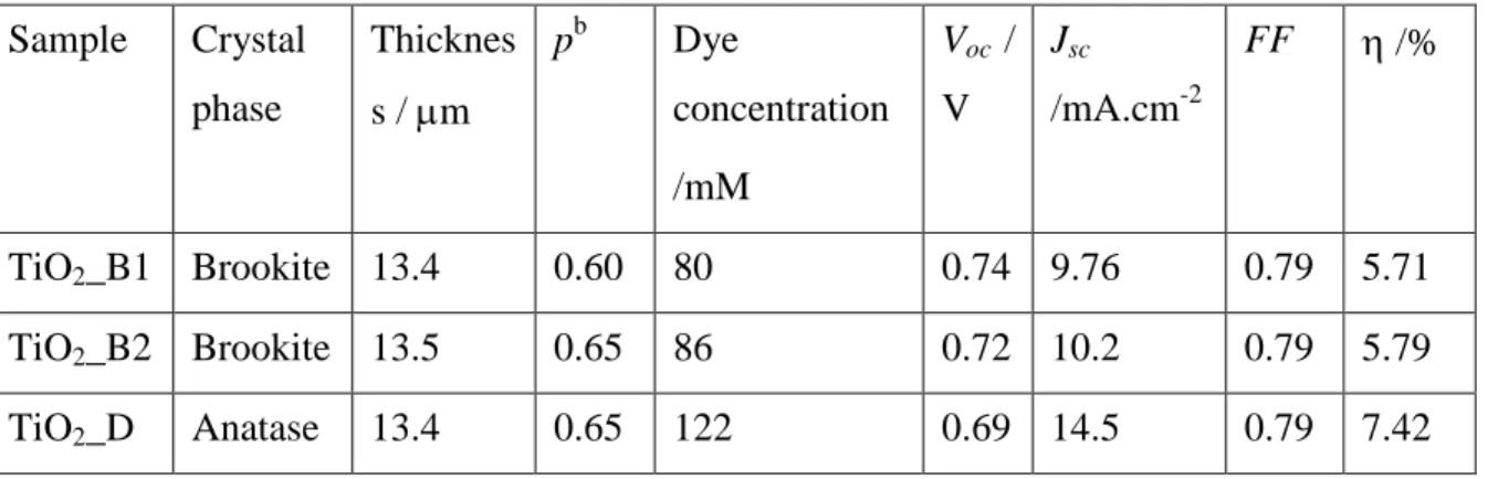
Table 4.1 Dye loading and cell characteristics under 100 mW.cm-2, AM 1.5G filtered illumination. ... 76
Table 4.2 , T0andparameters extracted from the C(Vcor) and Rct(Vcor) curve analysis. ...80
Table 4.3 Analysis of the open circuit voltage difference between anatase and brookite cells... 80
Table 4.4 Calculation of∆ࡱࢇࢊ࢙of I2adsorption on anatase (101) and brookite (210) surface ....89
Table 5.1: Effect of composite SGO content on the specific surface area determined by BET (SBET), on the sensitized layer dye concentration and on the maximum of absorbance at 530 nm... 104
Table 5.2 I-V curve parameters of TiO2_A and various TiO2_Gr cells ...107
Table 5.3 ,and T0value of TiO2_A and TiO2_Gr that is extracted from IS Spectra ...110
Table 5.4. The comparison of Z907 sensitizd cell performances using (Co[bpy]2) 3+ and NOBF4as source of Co 3+ ...117
Table 5.5. The effect of ligand on cell performances ...117
Table 5.6 Effect of Co(II)/NOBF4molar ratio on Z907-sensitized cell performances ...118
Table 5.7. Cell parameters for TiO2_Gr12 cobalt-based DSSC experiment ...120
Table 5.8 I-V parameters of Z907 sensitized TiO2_A and TiO2_Gr12 solar cells with iodine (I2-2 ) and cobalt-based electrolytes (Co-6) ...121
Table 6.1 Dye molar extinction coefficient and I-V curve characteristic under 100 mW.cm-2, AM 1.5 G filtered illumination ...132
Table 6.2. Calculated TD-DFT spectra of TG6 and D149 above 350 nm with oscillator strength, f > 0.1 ... 139
Table 6.3 I-V characteristics using iodine redox-couple (I2-2) ...143
Table 6.4 I-V characteristics of SD4 using various cobalt redox-couples ...144
Table 6.5: I-V characteristics of JM164- and JM131-based cell using [Co(bpy-pz)2]2+/3+ and I3-/I- redox-couples ...145
Table 6.6. I-V measurement of JM164 cell using [Co(bpy-pz)2] 2+/3+ and I3 -/I-as redox couple, without the addition of TBP in electrolyte. ...146
Table 6.7 The I-V chareacteristics of cell with a 5 µm photoelectrode thickness using JM164 sensitizer... 147
Table 6.8 The I-V characteristics of JM164 sensitized ZnO_C20 based cells ...150
Table 6.9 Calculated TD-DFT spectra of SD4, JM131 and JM164 above 350 nm with oscillator strength, f > 0.1 ...153
Table 6.10 The qCTand dCTof SD4, JM131 and JM164 calculated using CT model ... 155
Table 6.11 The calculated excited states lifetime of SD4, JM131 and JM164 ...156
List of Appendix
APPENDIX A: Crystallites Size Determination ... 164
APPENDIX B: Porosity Determination using Direct Method ... 168
APPENDIX C: Optical Band-gap Calculation... 169
APPENDIX D: Dye Loading Calculation ... 173
APPENDIX E: Molar Extinction Coefficient Calculation ... 176
APPENDIX F: Photocatalytic Properties of TiO2_Gr layer ... 179
APPENDIX G: Cobalt Complexes Preparation ... 185
APPENDIX H: Input File Gaussian Explanation ... 185
APPENDIX I: Input File CP2K Explanation ... 189
APPENDIX J: The Computational Procedure to Quantify Charge Transfer ... 191
List of the Important Abbreviations and Symbols
a Absorbance
B3LYP Three-parameter hybrid functional
bpy 2,2’-bipyridine
bpy-pz 6-(1H-pyrazol-1-yl)-2,2’-bipyridine
CAM-B3LYP Three-parameter hybrid functional that involved long-range correction
CB Conduction band
VB Valence band
c Speed of light : 3.108 m.s-1
Cµ Chemical capacitance of semiconductor due to electron trapping in states distributed below the conduction band edge
Deff Diffusion coefficient of electron in material
DEG Diethylene Glycol
DFT Density Functional Theory
DMF Dimethylformamide
DMPII 1,2-diméthyl-3-proplylimidazolium
DSSC Dye-sensitized solar cell
DOS Density of state
e or q Charge of electron : -1,6.10-19C
EC Ethylcellulose
ETL Electron Transport Layer
eV Electron volt
f Oscillator strength
FF Fill Factor
FTO Flouride dopped Tin Oxide
h Planck constance : 6,6.10-34J.s
HOMO Highest Occupied Molecular Orbital
HTL Hole Transport Layer
IPCE Incident photon-to-electron conversion efficiency
Jsc Short circuit current
kB Boltzman constance : 1,38.10-23J.K-1
KOH Potassium hydroxide
ln Diffusion length
LUMO Lowest Unoccupied Molecular Orbital
p Porosity of photoelectrode
phen 1,10-phenanthroline
PCE Power Conversion Efficiency
Rce Counter electrode resistance
Rct Resistance to charge transfer (recombination) across the sensitized oxide-electrolyte interface
RS Series resistance
Rtr Transport resistance of the electrons traveling in the mesoporous metal oxide films
R Light reflectance
SEM Scanning Electron Microscope
SGO Single Graphene Oxide
T Light transmission
TEM Transmission Electron Microscope
TiO2_A TiO2 particles which have anatase structure and were synthesized in this
TiO2_B TiO2 particles which have brookite structure and were synthesized in
collaboration with the Laboratoire de Chimie de la Matière Condensée de Paris, Collège de France, Paris, France
TiO2_D TiO2 particles which have anatase structure and were buy from DSSC
Company, Dyesol® as a paste
TiO2_Gr Composite of TiO2anatase and graphene
TCO Transparent Conductiove Oxyde
XRD X-Ray Diffraction
Voc Open circuit voltage
Z Elextrical Impedance
ZnO_NR ZnO rod-like nanoparticles
α a parameter that corresponds to the depth of the distribution
β an empirical estimation of the reaction order
ε Coefficient extinction molar
ε0 Vacuum permittivity = 8.85419 x 10⁻¹²F.m-1 ℏ Reduced planck constant = 1.05 x 10⁻³⁴J.s
η Cell efficiency = PCE
ηcoll Charge collection effeciency
λ Wavelength
ν Light frequency
σ Conductivity
τtr Transport time of electron in semiconductor
Chapter I: Introduction
I.1. Background
I.1.1. Solar Energy as an Alternative of Renewable Energy
Energy is one of the primary needs of human life. Nowadays, the consumption of energy is increasing not only because the population increase, but also because many activities are more and more energy dependent. Modern people who live in the high technology era need energy for various purposes including communication and transportation.
The fossil fuels, including coal, liquid fuels (oil/petroleum) and natural gas, are the major energy sources in the world that supplies 80% of the world energy demands (Asif and Muneer, 2007). Figure 1.1 displays the consumption of the fossil fuels from 1965 until 2030. This figure shows that the demand increases with time. As non-renewable energy source, the fossil fuels have disadvantages of a limited availability. In their article, Shafiee and Topal have calculated that the oil, coal and gas stocks are only sufficient for about 40, 200 and 70 years, respectively if assumed that the world-consumption rate is constant as 2006’s rate (Shafiee and Topal, 2009).
Another disadvantage of the fossil fuels is their negative effect on the environment. Their combustion releases the greenhouse CO2 gas in the atmosphere that provokes climate
change and global warming (Steinberg, 1999).
The issue of the fossil fuels limited availability and the global warming effect has become a global problem and has been discussed for years. This situation has encouraged many researchers to exploit the renewable energy sources. There are many kinds of renewable energy that have potency to be used, such as: wind, solar, geothermal, hydrogen, hydro-electric or biomass energies (Jacobson and Delucchi, 2011; Salameh, 2003).
One of the potential sources of renewable energy is the solar energy. It meets three criteria as energy source which are sustainability, cleanness and low-risk. These three criteria are important to maintain the energy system for a long term (Jacobson and Delucchi, 2011). The availability of the solar energy depends on geographical area and season/time. Solar irradiance on earth’s surface can reach 0.06 kW/m2 (at high latitudes) to 0.25 kW/m2(at low latitudes) (Timilsina et al., 2012). Figure 1.2 shows the average annual global solar irradiation. Many areas in the world, especially in the equator area, have high annual solar radiation. As a tropical country, Indonesia which is located between latitudes 6oN -11oN and longitudes 95oE-141oE, receives a solar radiation ranging between 4.6 kWh/m2 and 7.2 kWh/m2. The highest radiation is received in August and in September (Rumbayan et al., 2012). This makes Indonesia has a promising potential to develop a solar energy system.
Figure 1.2: Average annual global solar radiation (Devabhaktuni et al., 2013).
The solar energy can be utilized directly as a heat radiation without any changing to another form for instance in traditional drying process. This is a simple and low technology utilization. Since many of household and industrial equipments need electricity source, the solar energy can be more valuable by converting it to electricity. Solar technologies have an
important role to play and it has become a promising competitor for fossil fuels as the energy sources. The pioneer technology to convert the solar energy into a more usable one appeared in 1860. At that time they developed the technology to capture the sun’s heat. This heat was used to generate steam for running engines and irrigation pumps. Another typical electricity generating technology from the solar energy is photovoltaic (PV). The photovoltaic effect was discovered by Alexandre Edmond Becquerel in 1839. It is produced in semiconductor that can absorb light in the solar radiation spectrum range. This light absorption generates excitation charges, which are separated, provokes electron/hole flows, produces a voltage difference then finally generates the electricity. Since the first silicon solar cells fabrication in 1954 at the Bell Laboratories in the United States, until now there are many kinds of the PV technologies that have been developed. Figure 1.3 shows some example of the applications of solar cells.
(a) (b) (c)
Figure 1.3: Some applications of solar cells: (a) PV Solar parking canopy at the Autonomous University of Madrid, Spain; (b) Solar panels on the International Space Station; (c) Photovoltaic SUDI shade is an autonomous and mobile station in France that provides energy for electric vehicles
using solar energy; (http://en.wikipedia.org,2015).
Crystalline silicon-based solar cells are the leading technology in the solar cell market. Novel technologies to find out alternative materials which are less energy demanding to produce an that could replace the silicon one are also developing (Devabhaktuni et al., 2013; Timilsina et al., 2012). Figure 1.4 shows that global installed PVs capacity has increased exponentially from 1.4 GW in 2000 to 40 GW in 2010.
I.1.2. Dye-sensitized solar cells: towards iodine free devices.
Improvements in the solar cell field aim at increasing their efficiency and decreasing their production costs. One emerging technology of solar cells use a dye for sunlight harvesting in devices referred to as Dye Sensitized Solar Cells (DSSCs). They consist of a mesoporous semiconductor layer deposited on a transparent conductive oxide (TCO),
sensitized by a monolayer of dyes, and coupled with an electrolyte and a counter electrode. All components of DSSCs interacts each other at molecular level to build a stable and an efficient solar cell device. DSSCs can be small and light, so they can be easily applied to various electronic devices. They are mentioned as a candidate for the third generation of solar cells (Hagfeldt et al., 2010). Despite their advantages, their efficiency is still lower compared to the silicone-based solar cells. The research on improving their performances has been on-going for more than two decades. Figure1.5 shows that the number of publication on DSSCs has increased exponentially over this period, indicating that the interest on DSSC research is increasing. Moreover, they are emerging on the market of up-scaled energy provision with for instance the installation of large DSSC panels in Switzerland by Solaronix end G2e (Figure 1.5).
Figure 1.4: Total installed PVs capacity in the world (Timilsina et al., 2012).
Figure 1.5: Number of papers on DSSC published since their discovery. Data is taken from www.scopus.com with search keywords ”dye sensitized” and ”solar”
18 134 671 2789 7072 0 2000 4000 6000 8000 1990-1995 1996-2000 2000-2005 2006-2010 2011-2015 N um be ro fp ub lic at io ns Year range
(a) (b)
Figure 1.6: Two DSSC panels installations in Switzerland. (a) DSSC panel at EPFL campus, the world’s first solar window (http://actu.epfl.ch, 2011) (b) DSSC panel at Geneva Airport that is installed
by g2e in collaboration with EPFL (http://g2e.ch, 2013)
The “classical” DSSC, that was first introduced by Gratzel et. al. (O’Regan and Grätzel, 1991) in 1991 and has been became a standard for years, is composed of a mesoporous TiO2 electron transport layer sensitized by ruthenium complex dye as the
photoelectrode, an electrolyte containing the I3-/I- redox-couple and platinized conducting
glass as the counter electrode. In order to increase the cell efficiency, researchers have competed to modify each of the components. The highest efficiency of DSSC was achieved by using the TiO2mesoporous as the photoanode, the [Co(bpy)2]2+/3+as the redox-couple and
a porphyrin-dye, the SM 315 as the sensitizer. A record efficiency of 13% was achieved with this cell developed by Mathew and co-workers in the EPFL laboratory (Mathew et al., 2014). The usage of cobalt as redox-couple to replace the iodide one was based on the observation that employing the I3-/I-as the redox-couple has several limitation because it causes corrosion,
absorb the light in the 350-450 nm wavelength region and it has limited open circuit voltage due to its potential reduction value (Feldt et al., 2011, 2010; Hamann et al., 2006). On the other hand, the use of cobalt redox shuttles requires, (1) thinner photoelectrode layer to accommodate transport of bulky cobalt-complex and (2) special structure of sensitizer with long-alkyl chain and D-π-A characteristic to provide better charge separation and avoid the close approach of cobalt-complex to the photoanode surface and then reduce the recombination (Murakami et al., 2014; Yella et al., 2011). Mathew et. al. work focused on modifying the porphyrin sensitizer to improve cobalt based DSSC performance (Mathew et al., 2014). Since the synthesis of organic molecules need special technique and experience, it is important to do modification of others DSSC’s component in order to meet a better result when combined with cobalt-based electrolyte. Another strategy that can be applied to increase the DSSC effeciency is to improve the semiconductor as Electron Transfer Layers (ELT) in DSSC to have faster electron transport so it can compete with the charge recombination.
I.2. Objectives
Based on the above consideration and motivation, therefore, the objectives of this work have been set-up as follows: (1) to develop the use of new porous ETLs in DSSC application; (2) to investigate their functioning, for this pupose the cells were investigated in the I3-/I- based electrolyte; and (3) to investigate their use with new redox couples to get
iodine-free efficient devices, for this purposes the cell were investigated using Co2+/3+ based electrolyte. In order to perform in-depth investigations, there are three kind ETLs were developed in this work, i.e., the TiO2-brookite, the composite of TiO2/graphene and ZnO
nanorods (ZnO_NR) based DSSC. Furthermore, to have a description about the researches in this work, in the next section will be described the research approaches and the specific objectives of this work.
I.3. Research Approaches and Specific Objectives
This section will be devided based on the kinds of ETLs that were developed in this works; the TiO2-brookite, the composite of TiO2/graphene and ZnO nanorods (ZnO_NR)
based DSSC
I. 3.1. TiO2Brookite Based DSSC
TiO2-anatase has been used widely as semiconductor in DSSC application. Instead of
anatase, the other polymorph of TiO2, brookite also has promising potential to be used in
DSSC application. It has been done in the previous work in our laboratory that the Brookite based DSSC has a higher Voc, unfortunately the Jsc of brookite based DSSCs are lower
compare to the anatase ones (Magne et al., 2012). Revealing the origin of cell parameters will be beneficial as the material development consideration.
Based on this motivation, therefore, the specific objective of the work on this part is aimed at performing a comprehensive study using impedance spectroscopy to find out the origin of the cell paramteres to the cell functioning.
I. 3.2. TiO2/graphene Based DSSC
Graphene incorporation into TiO2 particle for DSSC photoelectrode is potentially of
great interest. Many reports show that graphene can improve the cell efficiency by increasing the current density (Jsc) without significantly decrease in the open circuit voltage (Voc) and fill factor (FF) (Cheng et al., 2013; Fang et al., 2014; Tang et al., 2010; J. Wang et al., 2012; Yang et al., 2010). One of factors that makes Jscincreasing is because there is an enhancement
in charge transport leading to electron transport increasing in photoelectrode after graphene incorporation (Fan et al., 2012; H. Wang et al., 2012). Although many reports have shown the improvement of DSSC performances by the addition of graphene, the effect ofthis additive on the cell functioning still needs to be clarified. In the present work, we have prepared anatase TiO2/graphene composite films using a simple sol−gel technique and graphene oxide single
layer sheets (SGO) as the graphene source.
On the basis of the above considerations, the specific objectives of this work are: (1) to clarify the role of RGO in cell improvement using comprehensive study of impedance
spectroscopy. This study was done using classical DSSCs, in the I3-/I-based electrolyte.
(2) to apply the TiO2/graphene composite on the cobalt-based DSSC. To the best of our
knowledge, there has been no previous report concerning the application of TiO2/graphene
DSSCs coupled with cobalt-based DSSCs. This works are motivated by the fact that the cobalt-complexes have a bulky structure that restricts their movement in the photoelectrode and provokes a reduction of the Jsc. We hope graphene presence in this cell can overcome the Jscreduction.
I. 3.3. ZnO_NR Based DSSC
As an alternative to TiO2, ZnO can also be used in DSSC. The use of ZnO is
promising due to the electronic properties of this oxide. Electron mobility and diffusion coefficient in ZnO is much higher than that in anatase TiO2. These properties are profitable
for DSSCs application because they support fast charge transport and electron recombination reduction (Quintana et al., 2007; Zhang et al., 2009). Moreover, the crystallization and anisotropic growth of ZnO crystal is relatively easy and allows the preparation of structures with various structural shapes.
In order to obtain further understanding, therefore, the specific objectives of the work on ZnO-based DSSCs study are as follows:
(1) to investigate the cell performances in classical I3-/I- using two kinds of sensitizers
(D149 as representative of organic sensitizer and TG6 as representative of organometallic/ruthenium sensitizer;
(2) to apply the ZnO_NR in the cobalt based DSSC. The used ZnO_NR particles were 35x110 nm in size. The layers presented also quite large pores. Their structural
properties have been shown promising to facilitate cobalt-complexes transport in their porous network.
1.4. Thesis Organization
The heart of this thesis is placed from Chapter IV to Chapter VI which is described about the result of the works. Before reach that part, there is an introduction in Chapter I which is described about the background, the objectives and the research map of this work. Whereas Chapter II explains about the literature review and Chapter III describes the experimental and computational procedure.
The impedance study results of anatase and brookite DSSC are presented in the Chapter IV. The computational study of iodine adsorption on Anatase and Brookite surface that support experimental result is also presented in this Chapter.
The study of TiO2/graphene-based DSSC is presented in the Chapter V. This work is
divided into two parts: the first work presents the key role of graphene incorporation into the TiO2 photoelectrode. For this study, we used the I3-/I- as a redox-couple and the N719 as a
sensitizer. In a second part we have investigated the TiO2/graphene cobalt-based DSSC. Z907
was used as a sensitizer then. Some optimizations have been done to find out the best cell performances.
The Chapter VI presents the result on ZnO_NR based DSSCs. In first part, the ZnO-NR cells were tested in the I3-/I- based electrolyte using D149 and TG6 as sensitizer. The
D149 was chosen as representative of organic dye, whereas the TG6 was chosen as representative of ruthenium dye. In a second part of Chapter VI, we discuss the optimization and the performance of the ZnO-NR based cells in the cobalt-based electrolyte system. The TD-DFT computational study of the dye used in this chapter is also discussed. The scheme of thesis organization is showed in Figure 1.7.
The experimental techniques used in the thesis are presented in the Chapter III. The Chapter II presents the literature review on the DSSCs that has attracted our consideration in making a work plans in this thesis. Some supporting experimental procedures are gathered in the Appendix. We have also enclosed in the Appendix the results of photocatalytic degradation of 4-chlorophenol using TiO2/graphene layer, a work that has been done in
collaboration with the J. Heyrovsky Institute of Physical Chemistry, v.i.i., Academy of Sciences of the Czech Republic.
Figure 1.7: Thesis organization. The purple, green and orange box will be discussed in chapter IV, V and VI, respectively.
References
Asif, M., Muneer, T., 2007. Energy supply, its demand and security issues for developed and emerging economies. Renew. Sustain. Energy Rev. 11, 1388–1413. doi:10.1016/j.rser.2005.12.004
Cheng, G., Akhtar, M.S., Yang, O.-B., Stadler, F.J., 2013. Novel Preparation of Anatase TiO2@Reduced Graphene Oxide Hybrids for High-Performance Dye-Sensitized Solar Cells. ACS Appl. Mater. Interfaces 5, 6635–6642. doi:10.1021/am4013374
Devabhaktuni, V., Alam, M., Shekara Sreenadh Reddy Depuru, S., Green II, R.C., Nims, D., Near, C., 2013. Solar energy: Trends and enabling technologies. Renew. Sustain. Energy Rev. 19, 555–564. doi:10.1016/j.rser.2012.11.024
Fang, X., Li, M., Guo, K., Liu, X., Zhu, Y., Sebo, B., Zhao, X., 2014. Graphene-compositing optimization of the properties of dye-sensitized solar cells. Sol. Energy 101, 176–181. doi:10.1016/j.solener.2013.12.005 Fan, J., Liu, S., Yu, J., 2012. Enhanced photovoltaic performance of dye-sensitized solar cells based on TiO2
nanosheets/graphene composite films. J. Mater. Chem. 22, 17027–17036. doi:10.1039/C2JM33104G Feldt, S.M., Gibson, E.A., Gabrielsson, E., Sun, L., Boschloo, G., Hagfeldt, A., 2010. Design of Organic Dyes
and Cobalt Polypyridine Redox Mediators for High-Efficiency Dye-Sensitized Solar Cells. J. Am. Chem. Soc. 132, 16714–16724. doi:10.1021/ja1088869
Feldt, S.M., Wang, G., Boschloo, G., Hagfeldt, A., 2011. Effects of Driving Forces for Recombination and Regeneration on the Photovoltaic Performance of Dye-Sensitized Solar Cells using Cobalt Polypyridine Redox Couples. J. Phys. Chem. C 115, 21500–21507. doi:10.1021/jp2061392
Hagfeldt, A., Boschloo, G., Sun, L., Kloo, L., Pettersson, H., 2010. Dye-Sensitized Solar Cells. Chem. Rev. 110, 6595–6663.
Hamann, T.W., Brunschwig, B.S., Lewis, N.S., 2006. Comparison of the Self-Exchange and Interfacial Charge-Transfer Rate Constants for Methyl- versus tert-Butyl-Substituted Os(III) Polypyridyl Complexes†. J. Phys. Chem. B 110, 25514–25520. doi:10.1021/jp0649697
Jacobson, M.Z., Delucchi, M.A., 2011. Providing all global energy with wind, water, and solar power, Part I: Technologies, energy resources, quantities and areas of infrastructure, and materials. Energy Policy 39, 1154–1169. doi:10.1016/j.enpol.2010.11.040
Magne, C., Dufour, F., Labat, F., Lancel, G., Durupthy, O., Cassaignon, S., Pauporté, T., 2012. Effects of TiO2 nanoparticle polymorphism on dye-sensitized solar cell photovoltaic properties. J. Photochem. Photobiol. Chem. 232, 22–31. doi:10.1016/j.jphotochem.2012.01.015
Mathew, S., Yella, A., Gao, P., Humphry-Baker, R., Curchod, B.F.E., Ashari-Astani, N., Tavernelli, I., Rothlisberger, U., Nazeeruddin, M.K., Grätzel, M., 2014. Dye-sensitized solar cells with 13% efficiency achieved through the molecular engineering of porphyrin sensitizers. Nat. Chem. 6, 242–247. doi:10.1038/nchem.1861
Murakami, T.N., Koumura, N., Kimura, M., Mori, S., 2014. Structural Effect of Donor in Organic Dye on Recombination in Dye-Sensitized Solar Cells with Cobalt Complex Electrolyte. Langmuir 30, 2274– 2279. doi:10.1021/la4047808
O’Regan, B., Grätzel, M., 1991. A low-cost, high-efficiency solar cell based on dye-sensitized colloidal TiO2 films. Nature 353, 737–740. doi:10.1038/353737a0.
Quintana, M., Edvinsson, T., Hagfeldt, A., Boschloo, G., 2007. Comparison of Dye-Sensitized ZnO and TiO2 Solar Cells: Studies of Charge Transport and Carrier Lifetime. J. Phys. Chem. C 111, 1035–1041. doi:10.1021/jp065948f
Rumbayan, M., Abudureyimu, A., Nagasaka, K., 2012. Mapping of solar energy potential in Indonesia using artificial neural network and geographical information system. Renew. Sustain. Energy Rev. 16, 1437– 1449. doi:10.1016/j.rser.2011.11.024
Salameh, M.G., 2003. Can renewable and unconventional energy sources bridge the global energy gap in the 21st century? Appl. Energy, Energex 2002 - Oil and Gas - Topic III and Nuclear Energy - Topic IV 75, 33–42. doi:10.1016/S0306-2619(03)00016-3
Shafiee, S., Topal, E., 2009. When will fossil fuel reserves be diminished? Energy Policy 37, 181–189. doi:10.1016/j.enpol.2008.08.016
Steinberg, M., 1999. Fossil fuel decarbonization technology for mitigating global warming. Int. J. Hydrog. Energy 24, 771–777. doi:10.1016/S0360-3199(98)00128-1
Tang, Y.-B., Lee, C.-S., Xu, J., Liu, Z.-T., Chen, Z.-H., He, Z., Cao, Y.-L., Yuan, G., Song, H., Chen, L., Luo, L., Cheng, H.-M., Zhang, W.-J., Bello, I., Lee, S.-T., 2010. Incorporation of Graphenes in Nanostructured TiO2 Films via Molecular Grafting for Dye-Sensitized Solar Cell Application. ACS Nano 4, 3482–3488. doi:10.1021/nn100449w
Timilsina, G.R., Kurdgelashvili, L., Narbel, P.A., 2012. Solar energy: Markets, economics and policies. Renew. Sustain. Energy Rev. 16, 449–465. doi:10.1016/j.rser.2011.08.009
Wang, H., Leonard, S.L., Hu, Y.H., 2012. Promoting Effect of Graphene on Dye-Sensitized Solar Cells. Ind. Eng. Chem. Res. 51, 10613–10620. doi:10.1021/ie300563h
Wang, J., Tsuzuki, T., Tang, B., Hou, X., Sun, L., Wang, X., 2012. Reduced Graphene Oxide/ZnO Composite: Reusable Adsorbent for Pollutant Management. ACS Appl. Mater. Interfaces 4, 3084–3090. doi:10.1021/am300445f
Yang, N., Zhai, J., Wang, D., Chen, Y., Jiang, L., 2010. Two-Dimensional Graphene Bridges Enhanced Photoinduced Charge Transport in Dye-Sensitized Solar Cells. ACS Nano 4, 887–894. doi:10.1021/nn901660v
Yella, A., Lee, H.-W., Tsao, H.N., Yi, C., Chandiran, A.K., Nazeeruddin, M.K., Diau, E.W.-G., Yeh, C.-Y., Zakeeruddin, S.M., Grätzel, M., 2011. Porphyrin-Sensitized Solar Cells with Cobalt (II/III)–Based Redox Electrolyte Exceed 12 Percent Efficiency. Science 334, 629–634. doi:10.1126/science.1209688
Zhang, Q., Dandeneau, C.S., Zhou, X., Cao, G., 2009. ZnO Nanostructures for Dye-Sensitized Solar Cells. Adv. Mater. 21, 4087–4108. doi:10.1002/adma.200803827
Web References:
Photovoltaics. Wikipedia, the free encyclopedia , 2015. at
<http://en.wikipedia.org/w/index.php?title=Photovoltaics&oldid=642545739>, downloaded on January 28th, 2015.
EPFL's campus has the world's first solar window, 5thNovember 2011 at <http://actu.epfl.ch/news/epfl-s-campus-has-the-world-s-first-solar-window/>, downloaded on January 28th, 2015.
g2e launches first installation at Geneva International Airport, 9th April 2013 at <http://g2e.ch/views/media_newsletter/g2e_gva-vitre-orange-300dpi.jpg>, downloaded on January 28th, 2015
Chapter II
Literature Review
The important concepts at the background of the present thesis will be explained in this chapter. Dye-sensitized solar cell (DSSC) concepts will be explained in the first section including the device structure, charge transport in the device and the principle of cell characterizations that have been carried out in the present work. Computational investigation has been also carried out in this thesis to support experimental result; therefore the fundamental concepts in computational chemistry will be explained in the second section.
II. 1. Fundamental of DSSC
As defined in Chapter 1 DSSCs are photovoltaic devices that convert solar energy into electricity. For the conversion process to occur, it requires a dye that will act as the sensitizer to harvest the solar light, a semiconductor material which collects the charge generated in the excited dye and transfer it to the transparent front contact. The charge then must reach the counter electrode and oxidized dye is regenerated by a redox-couple dissolved in an electrolytic solution. We can note that chemical additives are added to the sensitizing dye solution and to the electrolyte to improve DSSC performances. Due to the versatility of the system, many different kind of DSSC have been described in the literature. The present thesis will focus on n-type DSSC devices, in which a wide bandgap n-type oxide plays a role as the electron transport layer (ETL) and a liquid electrolyte is used as the hole transport layer (HTL).
II. 1.1. DSSC Component
A Schematic illustration of a DSSC and of its components is presented in the Figure 2.1.
Dye Sensitizer
To achieve good performances, the dye sensitizer has to fulfill several requirements. (i) Ideally, it should be able to absorb all incident solar light below the near-IR wavelength of approximately 920 nm. (ii) Structurally, it must have functional groups that allow the anchoring of the dye onto semiconductor surface, classically a carboxylate or a phosphonate functional group. (iii) It must have the Lowest Unoccupied Molecular Orbital (LUMO) energy localized above the conduction band of the semiconductor to guaranty the electron
be localized below the redox potential of electrolyte. (v) At last, it must have good stability. If the dye still has good performance after 108 turnovers, it will equal to 20 years stability exposure to sunlight (Hagfeldt et al., 2010; Jena et al., 2012).
Figure 2.1: Schematic diagram of DSSC using I3
-/I-redox-couple
We can distinguish two main families of dyes that have been investigated for use in DSSCs. The first there are the metal complex compounds such as ruthenium, osmium, iron or zinc-based complexes and the second are the organic dyes including the indoline, coumarine or carbazole ones. Recently, Mathew, et. al. have successfully prepared cells with a 13% of efficiency using Zinc-Porphyrin complex dye (Mathew et al., 2014). Examples of dye molecular structure successfully used as sensitizer in DSSC are presented in Figure 2.2
The investigation of the dye electronic properties is very important to find out the electronic excitation behavior of the molecule which is related to its molecular structure. An efficient intramolecular charge transfer is required for a good cell performance. For this purpose, computational calculations are very helpful since they can describe electron density in the molecule. Moreover a first principle-based calculation technique, call TD-DFT (Time Dependent Density Functional Theory; see section II.2.2), it allows to reveal the electron excitation direction in the molecule upon the excitation process (Le Bahers et al., 2009; Marques and Gross, 2004; Runge and Gross, 1984). By comparing the calculated absorption spectrum with the experimental one, one can verify the accuracy of computational procedure.
Ruthenium dyes N N N N Ru2+ CO2H HO2C HO2C CO2H SCN SCN N3 N N N N Ru2+ CO2 -HO2C HO2C CO2 -SCN SCN N719 N N N N Ru2+ C9H19 H19C9 HO2C CO2H SCN SCN Z907 Porphyrin dye Zn N N O C8H17 O H17C8 N N O H17C8 O C8H17 N H13C6O H13C6O H13C6O H13C6O COOH S N N SM315 Indoline dyes D149 N S N OH O S N S CH3 O O D102 N S N OH O S O D131 N CN COOH Coumarine dye C343 N O COOH O Carbazole dye SD1 N N NC S S NC COOH N
The intense charge transfer must be oriented from the donor group in contact with the electrolyte solution towards the acceptor group localized near the semiconductor-surface anchoring group. In the case of ruthenium-complex dyes, the MLLCT (Metal and Ligand to Ligand Charge Transfer) process from ruthenium and thiocyanate groups to the bipyridine ligand carrying the carboxylate group is an efficient charge transfer that contributes to the high cell performances (Le Bahers et al., 2014). The presence of CN or NO group functions, for instance, that can increase the electron density near the carboxylate group are preferable (Funaki et al., 2014). On the contrary, the presence of substitute group that make electron density decrease around carboxylate moiety or shift far from carboxylate group must be avoided. Moreover, it is preferable to avoid the use of a ligand that is able to absorb light in the visible region or can undergo intra-Ligand to Ligand Charge Transfer (LLCT), since this type of charge transfer will not effectively increase electron density near the carboxylate group and the oxide surface (Le Bahers et al., 2014).
For organic dyes, the molecules that have D-π-A (donor- π spacer-acceptor) structure (Figure 2.3) are described to give the highest performances. The π-bridge between D-A systems acts as a light absorber unit. A longer π-bridge extends the absorption towards the longer wavelength region (Kim et al., 2013). The advantages of organic dye compared to metal-complexes are: (i) they are easier and cheaper to produce, (ii) they have a higher molar extinction coefficient that leads to highly efficient light-harvesting properties and (iii) it is possible to tune the desirable properties by inserting suitable substituent (Le Bahers et al., 2014; Ham and Kim, 2010).
Motivated by these potential advantages of organic dyes, many researchers have developed these sensitizers DSSC application (Alarco et al., 2007; Ganesan et al., 2014; Guérin and Pauporté, 2011; Hara et al., 2005; Ito et al., 2008; Magne et al., 2013b; Marinado et al., 2009). However, unfortunately, these efforts have not been fully successful yet. Based on the records of DSSC, metal complex compounds are still leading compared to the organic ones as a sensitizer in DSSC. As mentioned above, the highest efficiency reported for a DSSC employing an inorganic dye used a zinc-porphyrin complex dye, was coupled with cobalt-based electrolyte and reached 13% of (Mathew et al., 2014) On the other hand, the best performance of a DSSC employing an organic dye is 10.3 % using C219, as sensitizer (Zeng et al., 2010). Both are TiO2-based DSSCs.
The limitation of organic dyes notably lies on the aggregation of molecules that can happen. To achieve the best light-harvesting spectrum and a good electron intramolecular transfer, it requires a long-π bond and a planar geometry. However, this structure induces π- π stacking, and then causes aggregation of molecules (Kim et al., 2013). To overcome this, the addition of an anti-aggregation agent, for example chenodeoxycholic acid (CDA), is required. This agent will be adsorbed on semiconductor surface, it will make the inter-dyes distance longer and then limit the intermolecular aggregation. Based on their working principle, they are also called “co-adsorbent agent”. Magne, et. al. have investigated a series of fatty acids as co-adsorbents. They have shown that octanoic acid gives rise to better performances than CDA when combined with indoline dyes for ZnO-based DSSCs (Magne et al., 2012).
Another limitation is due to the poor electron to electricity conversion character of the D-π-A organic molecules. The presence of strong electron withdrawing molecule functions near to the anchoring group causes a charge entrapment effect that induces electron recombination. The phenomenon has been overcome by inserting another π-bridge into the molecule, to get the D- π-A π-A structure. This resulted in an increase of the incident-photon-to electron conversion efficiency from 20% incident-photon-to 90% (Haid et al., 2012; Kim et al., 2013).
Co-sensitization by two or more dyes is another strategy to improve the DSSC performances. By using two or more dyes that have different maximum absorption wavelength ranges, the absorption spectrum of the system will be broaden and become panchromatic. They will complement each other and then, finally, the light-harvesting efficiency will be increased. This approach has been used for instance using D131 as the co-sensitization dye of D205 and D149 dyes for ZnO based DSSCs. The absorption spectra of
the max of D149 and D205 dyes are localized at about 520-530 nm with a little weak
absorbance at 450 nm. By combining D131 with D149 and D131 with D205, the light harvesting was gave rise to an increase of the short circuit current Jsc(Figure 2.5.a). IPCE spectra of both systems, shown in Figure 2.5.b, confirm this result (Magne et al., 2013b).
Figure 2.4: Normalized dye absorbance of individual D131, D149 and D205 dyes and of equimolar dye mixtures (Magne et al., 2013b)
Figure 2.5: (a) J–V curves and (b) IPCE curves of ZnO DSSCs sensitized with D131, D149 and D131/D149 (Magne et al., 2013b)
The porphyrin family of inorganic dyes has attracted a considerable attention during the last few years. Porphyrins have important roles in biological processes, including catalysis, oxygen binding, electron transfer and photosynthesis. Their electronic absorption characteristic are interesting with two kinds of intense bands called Soret band (400-450 nm) and Q-bands (550-600 nm) (Kang et al., 2012). Their characteristics have inspired many researchers to prepare porphyrin derivatives compounds that can be applied as sensitizers in
DSSCs (Griffith et al., 2012; Kang et al., 2012; Lee et al., 2010; Mathew et al., 2014; Yella et al., 2014, 2011). Molecular modifications are needed in order to improve the light-harvesting properties of the basic porphyrin, especially at around 500 nm and beyond 600 nm. Inserting bulky donor moiety and combining with as the transition metal is the best approach up to now to achieve high performance prophyrin-based DSSCs (Griffith et al., 2012; Mathew et al., 2014; Yella et al., 2011). It has been mentioned above that the highest DSSC efficiency up to now is utilize Zinc-porphyrins dye as a sensitizer (Mathew et al., 2014). A non-certified power conversion efficiency of 13% was measured under full sun.
Transparent and Conductive Oxides (TCO)
TCO coated glass sheets are employed as substrates to deposit the photoanodes and the counter-electrodes. For the application, they must be transparent (Transmittance > 80%) and conductive (resistance < 10-3 cm). The two kinds of TCO mostly used in DSSC are ITO (indium tin oxide) composed of 90 wt % In2O3; 10 wt % SnO2and FTO (fluorine doped
tin oxide) (Magne, 2012). The effect of TCO on the DSSC performance has been studied by Sima, et. al. and they have shown that the cell that used FTO as substrate had efficiency 9.6 %. This result was very high compared to that of ITO substrate, for which the efficiency just reached 2.24%. Both of cell employed N3 dye sensitizer and AN50 iodolyte electrolyte from Solaronix. The outstanding performance of FTO was due to its resistivity which is smaller than that of ITO (8.5 /sq vs 18 /sq). Moreover, the FTO resistivity is more thermally stable. It did not change after heat treatment at 450°C, whereas ITO resistivity increased to 52 /sq after the same treatment (Sima et al., 2010) .
Unfortunately, FTO is a brittle material. Its mechanical brittleness then limit its usage (Jena et al., 2012). Flexible DSSCs are important for application, to make cells installed easily in building or electronic devices such as computer or mobile phone. Moreover, flexible DSSCs would be important for fabrication issue, to realize roll-to-toll mass production (Weerasinghe et al., 2013). Others materials, such as metal, carbon, plastic or others polymer have been studied to apply in order to make flexible DSSC.
Replacement of rigid substrate must address two issues, first the replacement of the photoelectrode substrate and second of the counter-electrode one. ITO/PEN (indium tin oxide coated polyethylene naphthalate sheets) or ITO/PET (indium tin oxide coated polyethylene terephthalate sheets) has been used widely as plastic substrate for photoelectrode. But, their utilization has limitations since these substrates have poor thermal stability require low
temperature photoelectrode processing. In the classical TiO2layer preparation, it will result in
the poor necking of TiO2nanoparticles and poor connection between TiO2 and the substrate.
Consequently the cell performances will be low due to limited electron transport (Wang et al., 2014; Wu et al., 2014b). Based on this issue, the research on flexible-photoelectrode have focused on finding the best metal-substrate (Kang et al., 2006; J.-Y. Liao et al., 2012; Wu et al., 2014b) or on overcoming electron transport issue in low-heat-treatment preparation (Jin et al., 2014; Jung et al., 2013).
We give now examples of the utilization of metal-based substrates for working electrode. Kang et. al. have prepared flexible working electrodes that consisted of TiO2coated
on both ITO and SIOx-sputtered stainless steel foils. Their cell reached an efficiency of 4.2%
under 100 mW/cm2 illumination (Kang et al., 2006). Liao et.al used Ti-Foil as substrate for the photoelectrode. They deposited hierarchical TiO2nanowire arrays on Ti-foils by two steps
hydrothermal reaction. Combining this working electrode with transparent PEDOT/ITO-PET (PEDOT poly-(3,4-ethylenedioxytiphene)) resulted in flexible DSSCs with a power conversion efficiency (PCE) of 4.32% (J.-Y. Liao et al., 2012). Ti based materials for flexible photoelectrode is the best choice compared to other metal due to their low corrosion properties but their opaque properties and the possibility of electron to trap in the TiO2
particle has limited cell performance (Wang et al., 2014; Wu et al., 2014b). Recently, Wu, et. al have prepared flexible photoelectrode that consisted of TiO2 nanoparticles on Ti-Foil
substrates. This photoelectrode had three layers of TiO2 with different structures, 1-D
nano-tubes, 3-D hierarchical microsized spheres and 0-D nanoparticles. The three layer design of photoanode TiO2 could enhance light harvesting and charge collection thus delivering a cell
PCE as high as 9.10% (Wu et al., 2014b).
Two main properties guide the research on flexible counter-electrodes: the conductivity and the capability of reducing tri-iodide (Chen et al., 2011; Hashmi et al., 2014; Hou et al., 2011; Yeh et al., 2011). Yeh, et. al have shown that the addition of titainum nitride nano-particles into poly(3,4-ethylene dioxythiophene):poly(styrene sulfonate) (PEDOT:PSS) matrix can increase the conductivity and they obtained flexible counter-electrode of DSSC with 5.82% of efficiency (Yeh et al., 2011). Other materials that have recently been studied as counter-electrode are carbon derivatives, such as activated carbon (Chen et al., 2011), carbon nanotube (Hashmi et al., 2014) and graphene (Roy-Mayhew et al., 2010). Carbon based materials have promising potential due to their inexpensiveness, chemical stability and good conductivity properties especially for carbon nanotubes and graphene allotrope.
Semiconductor
The semiconductor oxide plays an important role in DSSC. It receives electrons from photoexcited dyes attached on the surface and plays the role of the electron transport material ensuring the electron transfer to the front contact of the solar cell. To understand why wide bandgap semiconductors are used in DSSC photoanode, one has to describe the material’s electronic properties.
Based on their electric conductivity, solid states materials are divided into three categories, insulators, semiconductors and conductors. Their conductivity properties can be explained by revealing their solid state electronic properties. To start, let us take a look at the atomic scale. Every atom has atomic orbitals fulfilled by electrons and others that are empty. Orbitals filled with electrons have lower energy compare to the empty ones. The filled orbital that has the highest energy is called HOMO (Highest Occupied Molecular Orbital), and that one lowest-empty energy is called LUMO (Lowest Unoccupied Molecular Orbital). In the case of solid materials there are a large amount of atoms. As a consequence, the outermost shell, subshell and orbitals merge, providing a greater number of available energy levels, then finally form a continues energy-bands. Therefore the HOMO in an atom becomes valence band in solids whereas the LUMO becomes conduction band. In some solids, there is a distance between conduction and valence band called band gap. It is also called a forbidden band where there is no possibility to find electrons. Information regarding energy level energy in solid states materials can be presented in energy diagrams.
Figure 2.6 shows energy diagram of insulator, semiconductor and conductor. The bandgap in Insulator is the largest, above 6 eV at room temperature. It indicates that energy above this value must be transferred to excite electron from the valence band to the conduction band. On the contrary, conductor materials do not have a band gap and their conduction band is partially filled. Semiconductors have an intermediate electronic property between insulator and conductor. The most commonly used semiconductors are germanium and silicon which have a bandgap energy of 0.72 eV and 1.1 ev respectively (Sharma, 1996). The bandgap energies for oxide semiconductor are generally quite large, for example TiO2 =
Figure 2.6: Energy diagram schematic of insulator, semiconductor and metal
Due to these unique electronic properties, semiconductors are widely used in electronic devices. Their conductivity can be controlled by applying certain energy which is suitable with the band-gap energy. In the case of photovoltaic solar cell devices, solar light energy is the source to generate electric energy. There are many different kinds of solar cell devices. DSSC development is motivated by replacing the widespread silicon solar cells by low-cost solar cells. Anatase TiO2 has been chosen as a heart of DSSC due to its lower-cost,
availability, chemical stability and adsorption ability. However, the electronic properties of this material limit its application since the TiO2-band-gap energy (around 3.2 eV) is only
suitable for UV light absorption, which represents only ~ 5% of the solar spectrum. To broaden their absorbance spectral range towards the solar spectrum, TiO2 is sensitized with a
dye. Their conduction band energy level is suitable too with excited-sites energy level of many dyes. The breakthrough has been founded by Gratzel and O’Regan, who used mesoporous TiO2to apply in DSSC (O’Regan and Grätzel, 1991).
Aside from TiO2, there are others semiconductor that have promising potential to be
used since their electronic properties electronic properties is similar to TiO2. Figure 2.7 shows
an energy diagram of alternatives semiconductors along with energy level of some of redox-couples (Gong et al., 2012). ZnO is the most-commonly-studied semiconductor after TiO2.
This section will focus on TiO2 and ZnO, the two oxide semiconductor used in the present