Dual threshold voltage organic thin-film transistor technology
The MIT Faculty has made this article openly available.
Please share
how this access benefits you. Your story matters.
Citation
Nausieda, Ivan et al. “Dual Threshold Voltage Organic Thin-Film
Transistor Technology.” IEEE Transactions on Electron Devices 57.11
(2010): 3027–3032. Web.
As Published
http://dx.doi.org/10.1109/TED.2010.2072550
Publisher
Institute of Electrical and Electronics Engineers
Version
Final published version
Citable link
http://hdl.handle.net/1721.1/71816
Terms of Use
Article is made available in accordance with the publisher's
policy and may be subject to US copyright law. Please refer to the
publisher's site for terms of use.
flexible large-area integrated circuits is presented. The near-room-temperature (≤ 95◦C) process produces integrated dual
VT pentacene-based p-channel transistors. The two VT’s are
en-abled by using two gate metals of low (aluminum) and high (plat-inum) work function. The Al and Pt gate OTFTs exhibit nominally identical current–voltage transfer curves shifted by an amount ΔVT. The availability of a high-VT device enables area-efficient
zero-VGSoutput-resistance current sources, enabling
high--gain inverters. We present positive noise margin inverters and rail-to-rail ring oscillators powered by a 3-V supply—one of the lowest supply voltages reported for OTFT circuits. These results show that integrating n- and p-channel organic devices is not mandatory to achieve functional area-efficient low-power organic integrated circuits.
Index Terms—Digital integrated circuits, inverters, organic
compounds, thin-film transistors (TFTs).
I. INTRODUCTION
T
HIN-FILM transistors (TFTs) based on organic semicon-ductors offer the potential of large-area mechanically flex-ible integrated circuits due to their low temperature processing. For this reason, organic TFTs (OTFTs) have received much attention in the past ten years, during which there have been sig-nificant advances in OTFT performance. Pentacene is currently the organic semiconductor of choice for OTFTs due to its high hole mobility and environmental stability. Mobilities have been reported in excess of 1 cm2/Vs, equaling the performance ofamorphous silicon [1], [2].
Although pentacene OTFTs have been demonstrated with impressive electronic performance, there have been very few reports of functional digital OTFT circuits. OTFT technologies make circuit design challenging for three reasons: 1) the ab-sence of a complementary device; 2) the value of the VT; and
3) the lack of resistors. To improve OTFT technology, a number of technological enhancements have been proposed.
Manuscript received October 20, 2009; revised July 5, 2010; accepted July 27, 2010. Date of current version November 5, 2010. This work was supported in part by the Focus Center Research Program (FCRP) Center for Circuits and Systems Solutions (C2S2) under Contract 2003-CT-888. The review of this paper was arranged by Editor J. Kanicki.
The authors are with the Microsystems Technology Laboratory, Massachusetts Institute of Technology (MIT), Cambridge, MA 02139 USA (e-mail: [email protected]).
Color versions of one or more of the figures in this paper are available online at http://ieeexplore.ieee.org.
Digital Object Identifier 10.1109/TED.2010.2072550
organic semiconductors are typically hole transporters, small molecule materials such as hexadecafluorocopperphthalo-cyanine (F16CuPc) have been demonstrated to be suitable
electron transporters [3]. State-of-the-art organic digital circuits were created by Klauk et al. by shadow-mask patterning pen-tacene and F16CuPc. Unfortunately, the use of shadow masking
prohibits patterning large areas with small features due to bowing of the metal shadow mask. Yan et al. also report printed hole and electron transporting semiconductors but employed shadow masking in the device fabrication [4]. In addition, the integration of an n-channel device is only clearly advantageous if the electron mobility is comparable with the hole mobility of pentacene. For example, the electron mobility in [3] is 30× less than the hole mobility.
Another approach is to fabricate OTFTs with top and bot-tom gates, one of which is used to control the threshold voltage. Conventional enhancement-mode devices with back gates have been demonstrated in inverters with improved noise margins [5], [6]. This process requires the control of both pentacene–dielectric interfaces to achieve reproducible gate control. The added complexity and second power supply make this method unattractive.
In this paper, we present a dual-gate metal process to achieve integrated pentacene OTFTs with two threshold voltages. The current–voltage transfer characteristics of the aluminum and platinum devices are nominally identical but shifted by ΔVT.
To the best of the author’s knowledge, this is the first report of OTFT VT control by changing gate materials. The
high-work-function platinum gate device exhibits a high VT (i.e.,
more depletion like) and, by shorting its gate to source, can be used as an area-efficient current source with high output resistance. The integrated process is used to fabricate inverters and ring oscillators and can support the design of analog circuits such as amplifiers and comparators. These dual VT
circuits use 30× less area than a single VT implementation, assuming a trip voltage of VDD/2. Powered by a 3-V supply,
the nonoptimized inverter was measured to have a noise margin low (NML) of 1.3 V, a noise margin high (NMH) of 0.3 V,
and a current of 8 pA at the switching point. An 11-stage ring oscillator swings near rail-to-rail (0.05–2.85 V), with an inverter delay of 27 ms. Due to the low voltage operation and the small feature size enabled by photolithography, this paper has significantly better power-delay products than other works [3]. The inverters shown here use one of the lowest VDDs of any
3028 IEEE TRANSACTIONS ON ELECTRON DEVICES, VOL. 57, NO. 11, NOVEMBER 2010
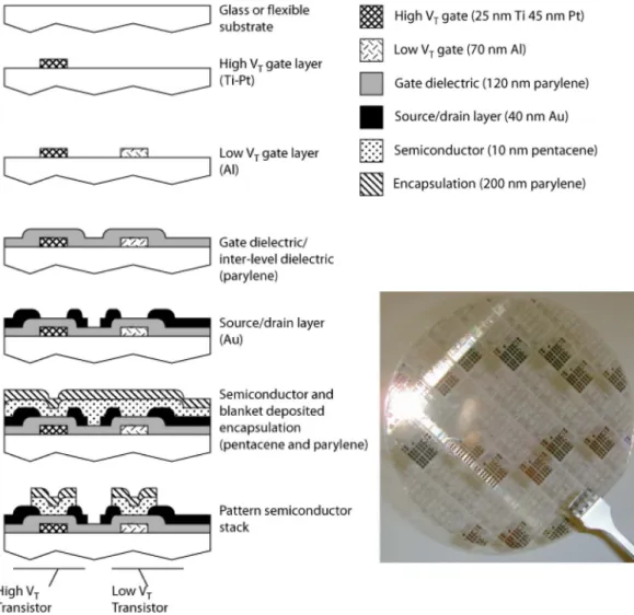
Fig. 1. Process flow for integrated dual VTOTFTs and photograph of a finished 100-mm wafer.
OTFT technology, photolithographically processed or not [4], [7]–[10].
II. DUALVT PROCESSFLOW
A near-room-temperature (≤ 95 ◦C) photolithographic process is used to fabricate integrated gate bottom-contact dual VT OTFTs. The process is implemented using
glass substrates, but its low temperature allows the use of flexible substrates. The process flow is depicted in Fig. 1, along with a photograph of a finished wafer.
All fabrication steps are done in a class 100 clean room. Float glass wafers (100 mm) are first cleaned in a 3:1 H2O2:
H2SO4 (piranha) solution for 10 min. The high-VT (more
depletion-like) gate pattern is transferred by image reversal photolithography, followed by a descum for 10 min in a bar-rel asher. Ti (25 nm) followed by Pt (45 nm) is electron-beam evaporated. The wafers are immersed in acetone and left overnight. A sonication in fresh acetone completes the liftoff process. Image reversal photolithography is next done for the low-VT gate (more enhancement-like) in the same
man-ner. After descum, 70 nm of Al is electron-beam evaporated. Liftoff is done in the same way as the Pt gate. After removal from acetone, the wafers are rinsed in deionized (DI) water,
blown dry with nitrogen, and immediately loaded for dielectric deposition.
Parylene-C, an organic polymer, is used as the gate dielec-tric. Parylene (130 nm) (Galaxyl) is deposited by hot filament chemical vapor deposition while the substrate remains at room temperature. The run-to-run variation of the gate dielectric thickness is about 5%. We have not concentrated on optimizing this yet.
Via holes are patterned by photolithography and a reactive ion etch in oxygen plasma. Photoresist is stripped by immersion in a solvent photoresist stripper (Microstrip 2001), followed by a DI wafer rinse and nitrogen blow dry.
Au (40 nm) is deposited by electron-beam evaporation and patterned by standard photolithography. Since the process is not self-aligned, a gate–source and gate–drain overlap of 5 μm is included. The gold layer is wet etched in a solution of 5 : 1 H2O:Transene TFA gold etchant (KI/I2). The photoresist
is removed with Microstrip, and the wafers are rinsed in DI water and blown dry. Pentacene (10 nm) is thermally evaporated at 0.5 nm/min. Since the dielectric and the semiconductor of the two VTdevices are processed at the same time, we expect
nom-inally identical dielectric–semiconductor interfaces for both devices. The pentacene deposition is immediately followed by a 200-nm blanket deposition of parylene-C. The parylene serves
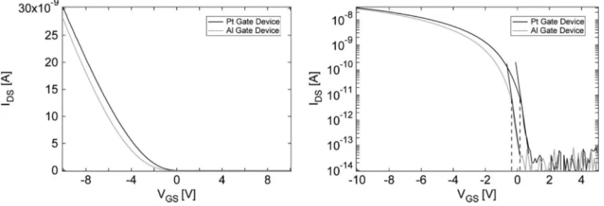
Fig. 2. (a) Measured linear transfer curves for adjacent W/L = 200 μm/15 μm sized Al and Pt OTFTs at VDS=−1 V. (b) Measured semilogarithmic transfer
curves for the same 200 μm/15 μm OTFTs at VDS=−1 V. The VTis extracted by drawing a straight line fit in the subthreshold region and taking the voltage
at which it pulls away. In this case, VT ,Al=−0.5 V, VT ,Pt= 0.1 V. The Pt device conducts 100× more current at VGS= 0 than the Al device.
as an encapsulant and prevents pentacene from exposure to subsequent solvent processing [11]. The pentacene–parylene stack is patterned photolithographically and etched in oxygen plasma, thereby defining the active region for each OTFT.
III. DUALVT DEVICEPERFORMANCE
The fabricated devices are electrically characterized using an Agilent 4156C semiconductor parameter analyzer. Current– voltage and capacitance–voltage measurements are taken to ex-tract device parameters such as Cox, subthreshold slope, contact
resistance, and mobility. The Coxis 22.3 nF/cm2, and at a VSG
of 3 V, we measure a typical mobility of∼0.01 cm2/Vs [12].
We observe no difference in these parameters compared with the standard single VT photolithographic process previously
reported [13]. In addition, no difference in these parameters is observed between the Al and Pt gate devices. We observe a variation between the as-drawn and measured device width of 2 μm. Therefore, we choose 20 μm as the minimum device width in circuit designs. The channel length is patterned via a different wet chemical etch, and optical microscopy indicates that the fabricated channel length differs from the as-drawn by 100 nm or less.
Fig. 2(a) plots the linear and semi-log transfer characteristics for typical dual VT devices. The threshold voltage is extracted
by applying a linear fit to the subthreshold regime in the semi-log curve and noting the VGSat which the I–V pulls away from
the line. This process is shown in Fig. 2(b). The current–voltage curves are nominally identical, except shifted by an amount we call ΔVT. A consistent ΔVT of 0.6 V is observed over multiple
wafers and lots. In each die, we extract the VT of the Al and
Pt gate devices and the shift in VT between them ΔVT. Table I
shows the mean and standard deviation of the threshold voltages and ΔVT.
The flatband condition for the TFT is written as
VT = (ΦGate− ΦPentacene)−
Qf CGate
(1) where Qf is the fixed charge (in coulombs per square
centime-ter) at the pentacene–parylene interface [6]. Since these devices operate in accumulation, we have referred to this voltage as VT
TABLE I
STATISTICS OFVTANDΔVTACROSSTHREEWAFERS. VTEXTRACTED ASSHOWN INFIG. 2. FOUR TOFIVEDIESMEASURED PERWAFER
to be consistent with OTFT literature. The work function values are referenced to the vacuum level.
By writing (1) for both metal gate devices, inserting the work functions of platinum and aluminum, and taking the difference, one can calculate the expected VT difference between the two
devices. Assuming uniform pentacene potential and parylene thickness across the wafer and no variation in fixed charge, the difference in flatband voltages should be proportional to the difference in metal work functions. Using work functions of 5.65 and 4.28 eV for platinum and aluminum, respectively, one would expect a difference in VT between devices to be around
1.3 V [14].
We suggest two reasons for the difference in expected and observed threshold voltages. It is known that the presence of water on a metal surface will change the surface potential [15], [16]. Contamination of the metal surfaces through processing or residual water layers on the gates may lead to the effective work function difference of 0.6 V.
IV. INVERTERDESIGN ANDCHARACTERISTICS
Conventional OTFT technologies are resistorless and con-tain a single VT p-channel device. The lack of a
3030 IEEE TRANSACTIONS ON ELECTRON DEVICES, VOL. 57, NO. 11, NOVEMBER 2010
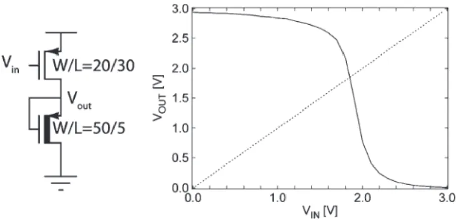
Fig. 3. (a) Dual VTinverter with low VTdriver and high VTzero-VGSload. (b) Measured transfer characteristics VDD= 3 V. Noise margin high (NMH) =
0.3 V, noise margin low (NML) = 1.3 V, VDD= 3 V.
difficult. In a p-channel-only process, there are two approaches one could take: use 1) a diode-connected OTFT load or 2) a zero-VGSload [17].
Diode-load inverters have asymmetric transfer characteristics and low gain, making it difficult to achieve positive noise mar-gins [7]. The zero-VGSload provides a higher output resistance
and thus higher gain, while allowing the inverter to be designed to trip near VDD/2. Given the gate-voltage-dependent mobility
in OTFTs, the zero-VGSload must be significantly wider than
the driver to achieve positive noise margins [12], [18]. Not only does this make the area of the inverter large, it also increases the CGD of the load transistor, decreasing the inverter speed.
A dual threshold voltage technology alleviates this problem by enabling area-efficient high-output-resistance zero-VGScurrent
sources. Since the Pt gate device sinks 100× more current than the Al device at VGS= 0, using the high VT device as the load
reduces its area by two orders of magnitude.
An area-minimized inverter schematic is shown in Fig. 3. Hand calculations were used to size the devices. The inverter was designed to maximize noise margins and trip at VDD/2
while also minimizing the area. The measured transfer curve is asymmetric, as are the noise margins, since the fabricated load device’s VT was 200 mV more negative than was used in the
hand designs.
The dual VT inverter uses 30× less area and reduces the load
capacitance by 17× compared with a single VT implementa-tion, assuming the single VT topology is sized such that VM = VDD/2. The measured inverter characteristics are pictured in
Fig. 3. The inverter was found to have a noise margin high of 0.3 V and a noise margin low of 1.3 V when powered by a 3-V supply [19]. The Pt gate device’s VTwas slightly more negative
than was used in hand calculations, causing the inverter to trip at 1.8 V instead of at 1.5 V. The load would need to be twice as wide (W = 100 μm, L = 5 μm) to trip at 1.5 V. The current at the trip point VIN= VOUTwas 8 pA. The off currents
(VIN= 0 V, VIN= VDD) were 9 pA and 480 fA, respectively.
If the inverter was instead optimized for speed and not area, then we estimate that an inverter delay of 7.7 ms would be expected with a driver W/L = 20 μm/5 μm and load W/L = 300 μm/5 μm while sinking 48 pA at its trip point.
These results compare favorably to state-of-the-art shadow-masked organic complementary metal–oxide–semiconductor
digital circuits. The dual VT inverter presented here uses 40×
less area, 10 000× less switching current, and 10–20× less static current (VIN= 0 V, VIN= VDD, respectively) compared
with the complementary inverters reported in [4]. The dual
VT inverter’s power-delay product is over 50× lower at 5.6 × 10⁻¹³J compared with an estimated 3× 10⁻¹¹J. The improved power-delay product is due to the small feature sizes enabled by using a photolithographic process.
It should be noted that integrating an n-channel device does not necessarily improve performance compared with the p-channel-only dual VTprocess. In the dual VT design, the load
is sized with a W/L of 15× larger than the driver in order for the inverter to trip at VDD/2. If we were to replace the
zero-VGS load with an NMOS device, then assuming a symmetric
VT with the p-channel TFT, the NMOS would need to be sized
Z times wider than that p-channel driver. Z is equal to the ratio
of the PMOS hole mobility to the NMOS mobility Z = μh/μe. Therefore, an n-channel device would only be clearly superior to the zero-VGSload if Z < 15.
V. RINGOSCILLATOR
An 11-stage ring oscillator with output buffer is fabricated and tested using the dual VT process. The inverter topology is
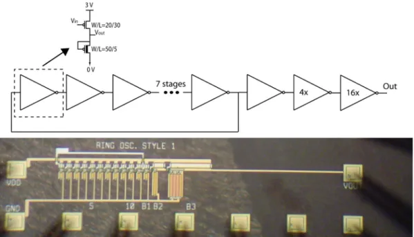
the same design as shown in Fig. 3. The circuit schematic for the ring oscillator is shown in Fig. 4.
The ring oscillator is powered by a 3-V supply. Fig. 5 plots the measured 1.7-Hz waveform, which corresponds to an inverter propagation delay of 27 ms [20]. In comparison, the inverter propagation delay reported in [3] is 2.3 ms, and 700 μs in [10]. Despite our small feature size, the gate de-lay is larger in the dual VT implementation due to the low
mobility. This is a result of the unoptimized pentacene depo-sition and poorer charge transport compared with other films reported [1]–[3]. This is in part due to our bottom-contact device architecture, which is necessary to ensure compatibility with standard photolithography. In addition, it has been widely reported that the vertical electric field increases mobility, and these devices operate at lower vertical fields than other reports [3], [10].
The ring oscillator output swings from 0.05 to 2.85 V. Although other OTFT ring oscillators have been published,
Fig. 4. Schematic and die photo of 11-stage dual VTring oscillator with output buffer.
Fig. 5. Measured 1.7-Hz ring oscillator output, corresponding to an inverter delay of 27 ms. VDD= 3 V.
many do not swing near rail-to-rail and thus are not an accurate measure of the inverter propagation delay.
VI. CONCLUSION
A near-room-temperature process with two gate metals for integrated dual VT OTFTs has been introduced. Devices are
electrically characterized and are found to be nominally identi-cal but shifted by ΔVT = 0.6 V.
An area-minimized integrated dual VT inverter is fabricated
and characterized, offering 30× area savings over a single VT topology. The inverter has NMH = 0.3 V and NML= 1.3 V
and uses∼24 pW of power with a 3-V supply.
An 11-stage ring oscillator using the inverter design is fab-ricated and tested, demonstrating rail-to-rail operation and an inverter delay of 27 ms.
ACKNOWLEDGMENT
I. Nausieda would like to thank M. Bieniosek for help in characterizing devices. The devices were fabricated in MIT’s Microsystems Technology Laboratory.
REFERENCES
[1] H. Klauk, M. Halik, U. Zschieschang, G. Schmid, and W. Radlik, “High-mobility polymer gate dielectric pentacene thin film transistors,” J. Appl. Phys., vol. 92, no. 9, pp. 5259–5263, Nov. 2002.
[2] D. J. Gundlach, H. Klauk, C. D. Sheraw, C. C. Kuo, J. R. Huang, and T. N. Jackson, “High-mobility, low voltage organic thin film transistors,” in IEDM Tech. Dig., Dec. 1999, pp. 111–114.
[3] H. Klauk, U. Zschieschang, J. Pflaum, and M. Halik, “Ultralow-power organic complementary circuits,” Nature, vol. 445, no. 7129, pp. 745– 748, Feb. 2007.
[4] H. Yan, Z. Chen, Y. Zheng, C. Newman, J. R. Quinn, F. Dotz, M. Kastler, and A. Facchetti, “A high-mobility electron-transporting polymer for printed transistors,” Nature, vol. 457, no. 7230, pp. 679–687, Feb. 2009. [5] M. Takamiya, T. Sekitani, Y. Kato, H. Kawaguchi, T. Someya, and
T. Sakurai, “An organic FET SRAM with back gate to increase static noise margin and its application to Braille sheet display,” IEEE J. Solid-State Circuits, vol. 42, no. 1, pp. 93–100, Jan. 2007.
[6] M. Spijkman, E. C. P. Smits, P. W. M. Blom, D. W. de Leeuw, Y. Bon Saint Come, S. Setayesh, and E. Cantatore, “Increasing the noise margin in organic circuits using dual gate field-effect transistors,” Appl. Phys. Lett., vol. 92, no. 14, pp. 143 304-1–143 304-3, Apr. 2008. [7] E. Cantatore, T. C. T. Geuns, G. Gelnick, E. van Veenendaal,
A. F. A. Gruijthuijsen, L. Schrijnemakers, S. Drews, and D. M. de Leeuw, “A 13.56-MHz RFID system based on organic transponders,” IEEE J. Solid-State Circuits, vol. 42, no. 1, pp. 84–92, Jan. 2007.
[8] M. G. Kane, J. Campi, M. S. Hammond, F. P. Cuomo, B. Greening, C. D. Sheraw, J. A. Nichols, D. J. Gundlach, J. R. Huang, C. C. Kuo, L. Jia, H. Klauk, and T. N. Jackson, “Analog and digital circuits using or-ganic thin-film transistors on polyester substrates,” IEEE Electron Device Lett., vol. 21, no. 11, pp. 534–536, Nov. 2000.
[9] N. Gay, W. J. Fischer, M. Halik, H. Klauk, U. Zschieschang, and G. Schmid, “Analog signal processing with organic FETs,” in Proc. ISSCC Dig. Tech. Papers, Feb. 2006, pp. 1070–1079.
[10] Y. Xia, W. Zhang, M. Ha, J. H. Cho, M. J. Renn, C. H. Kim, and C. D. Frisbie, “Printed sub-2 V gel-electrolyte-gated polymer transistors and circuits,” Adv. Funct. Mater., vol. 20, no. 4, pp. 587–594, Feb. 2010. [11] I. Kymissis, A. I. Akinwande, and V. Bulovi´c, “A lithographic process for
organic field-effect transistors,” J. Display Technol., vol. 1, no. 2, pp. 289– 294, Dec. 2005.
[12] K. Ryu, I. Kymissis, V. Bulovi´c, and C. G. Sodini, “Direct extraction of mobility in pentacene OFETs using C– V and I– V measurements,” IEEE Electron Device Lett., vol. 26, no. 10, pp. 716–718, Oct. 2005. [13] I. Nausieda, K. Ryu, I. Kymissis, A. I. Akinwande, V. Bulovi´c, and
C. G. Sodini, “An organic active-matrix imager,” IEEE Trans. Electron Devices, vol. 55, no. 2, pp. 527–532, Feb. 2008.
[14] H. B. Michaelson, “The work function of the elements and its periodicity,” J. Appl. Phys., vol. 48, no. 11, pp. 4729–4733, Nov. 1977.
3032 IEEE TRANSACTIONS ON ELECTRON DEVICES, VOL. 57, NO. 11, NOVEMBER 2010
[15] E. E. Huber, Jr. and C. T. Kirk, Jr., “Work function changes due to chemisorption of water and oxygen on aluminum,” Surf. Sci., vol. 5, no. 4, pp. 447–465, Dec. 1966.
[16] S. Meng, E. G. Wang, and S. Gao, “Water adsorption on metal surfaces: A general picture from density functional theory studies,” Phys. Rev. B, Condens. Matter, vol. 69, no. 19, pp. 195 404-1–195 404-13, May 2004. [17] S. De Vusser, J. Genoe, and P. Heremans, “Influence of transistor
parame-ters on the noise margin of organic digital circuits,” IEEE Trans. Electron Devices, vol. 53, no. 4, pp. 601–610, Apr. 2006.
[18] T.-C. Huang and K.-T. Cheng, “Design for low power and reliable flexible electronics: Self-tunable cell-library design,” J. Display Technol., vol. 5, no. 6, pp. 206–215, Jun. 2009.
[19] R. T. Howe and C. G. Sodini, Microelectronics: An Integrated Approach. Upper Saddle River, NJ: Prentice-Hall, 1997.
[20] J. M. Rabaey, A. Chandrakasan, and B. Nikolic, Digital Integrated Circuits: A Design Perspective. Upper Saddle River, NJ: Pearson Educational, 2003.
Ivan Nausieda (S’00) was born in Milwaukee, WI, in 1982. He received the B.S. degree in electrical and computer engineering from Carnegie Mellon University, Pittsburgh, PA, in 2004, the M.S. de-gree in applied physics from Harvard University, Cambridge, MA, in 2005, and the Ph.D. degree in electrical engineering from the Massachusetts Insti-tute of Technology (MIT), Cambridge, in 2009.
He is currently with the Microsystems Technology Laboratory, MIT.
Dr. Nausieda was the recipient of the Martin Fel-lowship for Sustainability.
Kevin Kyungbum Ryu (S’00) received the B.S. degree in electrical engineering from the Cooper Union for the Advancement of Science and Art, New York, NY, in 2003 and the M.S. and Ph.D. degrees in electrical engineering and computer sci-ence from the Massachusetts Institute of Technology (MIT), Cambridge, in 2005 and 2009, respectively.
He is currently with the Microsystems Technology Laboratory, MIT. His current research interests in-clude the processing and characterization of devices using novel materials such as graphene, organic, and metal–oxide thin-film transistors.
David Da He (S’08) received the B.A.Sc. degree in electrical engineering in 2005 from the University of Toronto, Toronto, ON, Canada, and the S.M. degree in electrical engineering in 2008 from the Massa-chusetts Institute of Technology (MIT), Cambridge, where he is currently working toward the Ph.D. degree in electrical engineering.
His current research interests include organic inte-grated circuits and biomedical electronics.
Akintunde Ibitayo (Tayo) Akinwande (S’81– M’86–SM’04–F’08) received the B.Sc. degree in electrical and electronic engineering from the Uni-versity of Ife, Ile-Ife, Nigeria, in 1978 and the M.S. and Ph.D. degrees in electrical engineering from Stanford University, Stanford, CA, in 1981 and 1986, respectively.
In 1986, he was with Honeywell Inc., where he was initially engaged in research on GaAs comple-mentary FET technology for very high speed signal processing and later on pressure sensors, accelerom-eters, thin-film field emission, and display devices. Since 1995, he has been with the Massachusetts Institute of Technology (MIT), Cambridge, where he is currently a Professor in the Department of Electrical Engineering and Computer Science. He is the holder of several patents in microelectromechanical systems (MEMS) and display technologies. His current research interests include de-vices for smart displays, large-area electronics, field emission, field ionization, gas analysis, electrospray, and electric propulsion.
Prof. Akinwande is a member of the Materials Research Society, the Society of Information Display, and the Electrochemical Society. He was on Technical Program Committees for various conferences, including the Device Research Conference, the International Electron Devices Meeting, the International Solid-State Circuits Conference, the International Display Research Confer-ence, and the International Vacuum Microelectronics Conference. He was the recipient of the 1996 National Science Foundation (NSF) CAREER Award.
Vladimir Bulovi´c received the B.S.E. and Ph.D. degrees from Princeton University, Princeton, NJ, in 1991 and 1998, respectively.
He is currently an Associate Professor of electri-cal engineering with the Massachusetts Institute of Technology (MIT), Cambridge, where he leads the Organic and Nanostructured Electronics Laboratory, codirecting the MIT-ENI Solar Frontiers Center and the MIT Solar Revolutions Project, and is coheading the MIT Energy Studies Minor. He is the Founder of QD Vision, Inc., Watertown, MA, which is focused on the development of quantum dot optoelectronics, and Kateeva, Inc., Menlo Park, CA, which is focused on the development of printed organic electronics. He is an Inventor of 45 U.S. patents in areas of organic and nanostructured light-emitting diodes, lasers, photovoltaics, photodetectors, chemical sensors, and programmable memories. His research interests include studies of the physical properties of organic and organic/inorganic nanocrystal composite thin films and structures, and the development of novel optoelectronic organic and hybrid nanoscale devices.
Charles G. Sodini (M’82–SM’90–F’95) received the B.S.E.E. degree from Purdue University, West Lafayette, IN, in 1974 and the M.S.E.E. and the Ph.D. degrees from the University of California, Berkeley, in 1981 and 1982, respectively.
He was a member of the technical staff at Hewlett-Packard Laboratories from 1974 to 1982, where he worked on the design of MOS memory. He joined the faculty of the Massachusetts Institute of Tech-nology, Cambridge, in 1983, where he is currently a LeBel Professor of electrical engineering. He was a cofounder of SMaL Camera Technologies, a leader in imaging technology for consumer digital still cameras and machine vision cameras for automotive applications. He also studied the Hong Kong/South China electronics industry from 1996 to 1997 and has continued to study the globalization of the electron-ics industry. Along with Prof. R. T. Howe, he is a coauthor of an undergraduate text on integrated circuits and devices entitled Microelectronics: An Integrated Approach. His research interests are focused on mixed-signal integrated circuit and systems with emphasis on analog, RF, and millimeter-wave circuit design. Dr. Sodini has served on a variety of IEEE Conference Committees, includ-ing the International Electron Device Meetinclud-ing, where he was the 1989 General Chairman. He has served on the IEEE Electron Devices Society Administrative Committee and was President of the IEEE Solid-State Circuits Society from 2002 to 2004. He is currently the Chair of the Executive Committee for the VLSI Symposia.