Publisher’s version / Version de l'éditeur:
Vous avez des questions? Nous pouvons vous aider. Pour communiquer directement avec un auteur, consultez la première page de la revue dans laquelle son article a été publié afin de trouver ses coordonnées. Si vous n’arrivez pas à les repérer, communiquez avec nous à PublicationsArchive-ArchivesPublications@nrc-cnrc.gc.ca.
Questions? Contact the NRC Publications Archive team at
PublicationsArchive-ArchivesPublications@nrc-cnrc.gc.ca. If you wish to email the authors directly, please see the first page of the publication for their contact information.
https://publications-cnrc.canada.ca/fra/droits
L’accès à ce site Web et l’utilisation de son contenu sont assujettis aux conditions présentées dans le site LISEZ CES CONDITIONS ATTENTIVEMENT AVANT D’UTILISER CE SITE WEB.
1st International Symposium on Laser Ultrasonics [Proceedings], pp. 1-7, 2008
READ THESE TERMS AND CONDITIONS CAREFULLY BEFORE USING THIS WEBSITE.
https://nrc-publications.canada.ca/eng/copyright
NRC Publications Archive Record / Notice des Archives des publications du CNRC :
https://nrc-publications.canada.ca/eng/view/object/?id=69eeebb6-d22a-439c-9caa-e3298eade692 https://publications-cnrc.canada.ca/fra/voir/objet/?id=69eeebb6-d22a-439c-9caa-e3298eade692
NRC Publications Archive
Archives des publications du CNRC
This publication could be one of several versions: author’s original, accepted manuscript or the publisher’s version. / La version de cette publication peut être l’une des suivantes : la version prépublication de l’auteur, la version acceptée du manuscrit ou la version de l’éditeur.
Access and use of this website and the material on it are subject to the Terms and Conditions set forth at
Integrated Piezoelectric Ultrasonic Receivers on Metals for Laser Generated Ultrasound
Integrated Piezoelectric Ultrasonic Receivers on Metals
for Laser Generated Ultrasound
Kuo-Ting WU 1,2, Cheng-Kuei JEN 1, Makiko KOBAYASHI 1 and Alain BLOUIN 1
1
Industrial Material Institute, National Research Council Canada, Boucherville, Quebec, J4B 6Y4 Canada; Tel: 450-641-5176, Fax: 450-641-5106, email: cheng-kuei.jen@cnrc-nrc.gc.ca;
kuo-ting.wu@cnrc-nrc.gc.ca; makiko.kobayashi@cnrc-nrc.gc.ca, alain.blouin@cnrc-nrc.gc.ca
2
Department of Electrical and Computer Eng., McGill University, Montreal, Quebec, H3A 2A7 Canada
Abstract
Thick (>50µm) piezoelectric ceramic films have been deposited directly onto metal substrates as integrated ultrasonic transducer (IUT) receivers to detect the laser generated ultrasound. The film fabrication is based on a sol-gel spray technique. In this investigation IUTs intrinsically acting as bulk longitudinal wave receivers use various mode conversion approaches and serve as longitudinal, shear, symmetric, anti-symmetric and shear horizontal plate wave receivers. Steel and aluminum having different sizes, shapes and thicknesses and coated with IUTs have been used for the study. Different laser generation conditions such as point and line sources of different sizes are also applied to investigate the capabilities of IUT receivers. Ultrasonic measurements up to 400°C of metal substrates with planar and curved surfaces using laser generated and IUT received ultrasound are demonstrated.
Keywords: Laser ultrasound, integrated ultrasonic transducer, high temperature, longitudinal and shear waves, plate acoustic waves, non-destructive testing (NDT)
1. Introduction
The generation of detectable ultrasound using pulsed lasers has been known since 1963 [1]. The mechanisms of laser generated ultrasound were reported and certain examples presented in [2,3]. Using lasers to generate ultrasound is an attractive and effective non-contact method in which the laser and the object may be meters away. In order to fully take advantage of such non-contact nature many detection approaches using optical means such as knife edge or position-sensitive detector [4,5] and various interferometers [6-8] to receive laser generated ultrasound were developed. Other non-contact detection techniques such as electromagnetic acoustic transducers [9], micro-machined capacitive [10] and piezoelectric air-coupled ultrasonic transducers (UTs) [11] have been also demonstrated. Merits of these contact methods include the ability to perform non-destructive testing (NDT) or characterization of materials having curved surfaces and at high temperatures. Furthermore laser beams can be considered as versatile UTs which may have adjustable transducer size, shape, and power and be arranged in array configuration and scanned in a reasonable speed using mirrors.
Recently sol-gel fabricated piezoelectric thick (>40µ m) films have been demonstrated being able to be coated onto planar and curved surfaces as integrated IUTs [12-14]. Such IUTs were successfully used in pulse/echo or transmission mode and operated at elevated temperatures in previous works [13-15]. The objective of this investigation is to explore the merits of combining the usage of lasers as the remote and versatile ultrasound generating UTs with that of IUTs as the receivers. When IUTs are used just as receivers, it is expected that the required electric power is low and thus battery driven or harvested energy driven approaches including wireless communication for NDT are feasible. The other expected advantages are that IUTs are miniature, light weight and
workable on curved surfaces and at high temperatures [13-15]. They can be also easily arranged in array configuration and have high piezoelectric sensitivities.
2. IUT fabrication and receiver sensitivity evaluation
2.1 Sol-gel fabrication technique
The piezoelectric composite film fabrication based on a sol-gel spray technique consists of six main steps [13,14]; (1) preparing high dielectric constant lead-zirconate-titanate (PZT) solution, (2) ball milling of piezoelectric ceramic powders such as PZT or bismuth titanate (BIT) [13,14] to submicron size, (3) sensor spraying using slurries from steps (1) and (2) to produce the thin film, (4) heat treating to produce a thin solid composite ceramic film such as PZT/PZT or BIT/PZT, (5) corona poling to obtain piezoelectricity, and (6) electrode painting or spray for top electrodes which define the IUT active area. Metal substrate itself serves as the bottom electrode of IUT. Steps (3) and (4) are used multiple times to produce optimal film thickness for specified ultrasonic operating frequencies of IUTs. The chosen electrode fabrication approach enables to achieve desired sensor configurations including interdigital transducers [14] and arrays conveniently.
2.2 Receiver sensitivity evaluation at 150°C
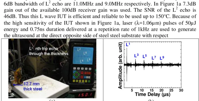
Figure 1a shows an IUT made of 51µ m thick PZT/PZT composite film and deposited onto a 12.7mm thick steel plate and measured by a handheld EPOCH model LT pulser-receiver (from Olympus-Panametrics, USA) at 150°C. EPOCH LT is commonly used for NDT by many industries. The relative dielectric constant of such composite film is around 80. The diameter of the top silver paste electrode of this IUT is 6.0mm. The measured ultrasonic data in pulse-echo mode is also presented in Figure 1a, where Ln is the nth trip L echo through the plate thickness. At 150°C the centre frequency and the 6dB bandwidth of L2 echo are 11.0MHz and 9.0MHz respectively. In Figure 1a 7.3dB gain out of the available 100dB receiver gain was used. The SNR of the L2 echo is 46dB. Thus this L wave IUT is efficient and reliable to be used up to 150°C. Because of the high sensitivity of the IUT shown in Figure 1a, laser (λ=1.06µ m) pulses of 50µ J energy and 0.75ns duration delivered at a repetition rate of 1kHz are used to generate the ultrasound at the direct opposite side of steel steel substrate with respect
(a) 5 10 15 20 25 30 A m p li tu d e ( a rb . u n it ) Time Delay (µs) L1 L3 L5 L7 L9 (b)
Figure 1. (a) Measurement setup for an IUT made of PZT/PZT composite film at 150°C using an EPOCH LT in pulse-echo mode; (b) Measured transmitted ultrasonic signals using laser
to the IUT. The laser beam spot size is 0.5mm diameter. Figure 1b shows the IUT received ultrasonic signals averaged of 10 laser pulses at 150°C. The centre frequency and 6dB bandwidth of L1 echo are 14.5MHz and 11.4MHz, respectively. The SNR of the L1 echo is 15.3dB. It is demonstrated that IUT made of PZT/PZT composite film is capable to be an excellent receiver for a 50µJ laser generated ultrasound up to 150°C.
3. Pulsed laser generation and IUT receiving of ultrasound at curved
surface and 400°C
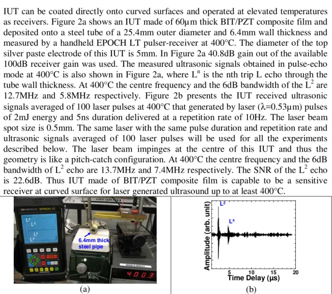
IUT can be coated directly onto curved surfaces and operated at elevated temperatures as receivers. Figure 2a shows an IUT made of 60µ m thick BIT/PZT composite film and deposited onto a steel tube of a 25.4mm outer diameter and 6.4mm wall thickness and measured by a handheld EPOCH LT pulser-receiver at 400°C. The diameter of the top silver paste electrode of this IUT is 5mm. In Figure 2a 40.8dB gain out of the available 100dB receiver gain was used. The measured ultrasonic signals obtained in pulse-echo mode at 400°C is also shown in Figure 2a, where Ln is the nth trip L echo through the tube wall thickness. At 400°C the centre frequency and the 6dB bandwidth of the L2 are 12.7MHz and 5.8MHz respectively. Figure 2b presents the IUT received ultrasonic signals averaged of 100 laser pulses at 400°C that generated by laser (λ=0.53µm) pulses of 2mJ energy and 5ns duration delivered at a repetition rate of 10Hz. The laser beam spot size is 0.5mm. The same laser with the same pulse duration and repetition rate and ultrasonic signals averaged of 100 laser pulses will be used for all the experiments described below. The laser beam impinges at the centre of this IUT and thus the geometry is like a pitch-catch configuration. At 400°C the centre frequency and the 6dB bandwidth of L2 echo are 13.7MHz and 7.4MHz respectively. The SNR of the L2 echo is 22.6dB. Thus IUT made of BIT/PZT composite film is capable to be a sensitive receiver at curved surface for laser generated ultrasound up to at least 400°C.
L2 L4 L6 L8 6.4mm thick steel pipe (a) 5 10 15 20 A m p li tu d e ( a rb . u n it ) Time Delay (µs) L2 L4 (b)
Figure 2. (a) Measurement setup and sample for an IUT made of BIT/PZT composite film at 150°C using an EPOCH LT and performed in pulse-echo mode; (b) Measured ultrasonic signals using
laser generated ultrasound and IUT as the receiver in pitch-catch mode at 400°C.
4. Pulsed laser generation and IUT receiving of bulk and plate waves
In this study, IUTs intrinsically acting as bulk longitudinal (L) wave receivers will use various mode conversion approaches [14,15] and serve as L, shear (S), symmetric, anti-symmetric and shear horizontal (SH) plate acoustic waves (PAWs) receivers.
4.1 Both L and S bulk waves
Figure 3a shows an IUT made of 80µ m thick BIT/PZT composite and deposited onto an edge of the steel block. The Lwave generated by the laser beam at the laser impinging plane will propagate along the block along the path parallel to the IUT plane and be reflected by the 45° angle plane shown in Figure 3a into the IUT L wave receiver. The S wave generated by the laser beam will propagate the similar way but be reflected with mode conversion [14] with an angle of 61.5° into the IUT L wave receiver. Figure 3b shows ultrasonic signal in time domain obtained from the same laser described in Section 3 but with pulses of 2mJ energy and spot size of 0.5mm diameter. The sample temperature is 400°C. In Figure 3b the L1 and S1 waves are obtained simultaneously. The ratio of their amplitudes can be controlled by the adjustment of the IUT top electrode area or the laser spot size and location below or above the dividing line. The L1 and S1 represent the first trip L and S wave echo, respectively, traversing between the laser impinging plane and L wave IUT. The center frequencies of the L1 and S1 echoes are 8.8MHz and 9.7MHz and the 6 dB bandwidths are 7.4MHz and 7MHz, respectively. Thus, laser generated L and S waves can be detected by IUT at 400°C simultaneously.
Laser Impinging Plane IUT 38mm 25mm 25mm θ=61.5° Dividing Line (a) 5 10 15 20 A m p li tu d e ( a rb . u n it ) Time Delay (µs) L1 S1 (b)
Figure 3. (a) Sample and measurement arrangement for both L and S waves; (b) Measured ultrasonic signals using laser generated ultrasound and IUT shown in Figure 3a as the receiver at 400°C.
4.2 Symmetric PAW in Al plate
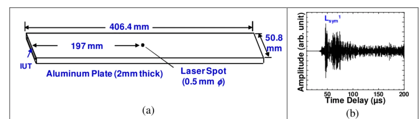
50.8 mm 406.4 mm
IUT
Aluminum Plate (2mm thick) 197 mm Laser Spot (0.5 mm φφφφ) (a) 50 100 150 200 A m p li tu d e ( a rb . u n it ) Time Delay (µs) Lsym1 (b)
Figure 4. (a) Sample and measurement arrangement for symmetrical PAWs; (b) Measured ultrasonic signals at room temperature.
An IUT made of 88µ m thick PZT/PZT composite with a top electrode area of 1.2mm in height and 46mm in length as the receiver is coated onto the edge of a 2mm thick, 50.8mm wide and 406.4mm long Al plate as shown in Figure 4a. Figure 4b presents the IUT received ultrasonic signals at room temperature that generated by the same laser described in Section 3 but with pulses of 4.4mJ energy and spot size of 0.5mm diameter.
The laser generation spot is about 197mm away from the IUT of the Al plate. Because the IUT shown in Figure 4a preferably receives symmetrical PAWs, Lsym, the PAWs
shown in Figure 4b are predominantly symmetrical PAWs. The centre frequency of the received Lsym1 echo is around 3.3MHz. It is demonstrated that symmetrical PAWs
generated by the laser can be detected by IUT on an Al plate.
4.3 Anti-symmetric PAW in steel plate
A 79µ m thick PZT/PZT composite with a top electrode area of 1mm in width and 45mm in length as the IUT receiver is coated onto the top of the edge of a 1.9mm thick, 50.8mm wide and 406.4mm long stainless steel (SS) plate as shown in Figure 5a. Figure 5b presents the IUT received ultrasonic signals at room temperature that generated by the same laser described in Section 3 but with pulses of 25mJ energy and line spot of 30mm long and 0.5mm wide. The generation laser line spot is about 228mm away from the IUT of the steel plate. The laser generated anti-symmetrical PAWs are mode converted [14,15] into L waves and received by IUT. The mode conversion angle φ is 62.6°. The centre frequency and the 6dB bandwidth of the received Lasym1 echo are
0.7MHz and 0.6MHz, respectively. This illustrates that anti-symmetrical PAWs generated by the laser can be detected by IUT on a SS plate.
62.6°
50.8 mm 406.4 mm
IUT
Stainless steel (1.9mm thick) 228 mm Laser Line (30 mm long 0.5mm wide) (a) 50 100 150 200 A m p li tu d e ( a rb . u n it ) Time Delay (µs) Lasym1 (b)
Figure 5. (a) Sample and measurement arrangement for anti-symmetrical PAWs; (b) Measured ultrasonic signals at room temperature.
4.3 SH PAW in Al plate and defect detection
61.7°
50.8 mm 406.4 mm
IUT Aluminum Plate (2mm thick)
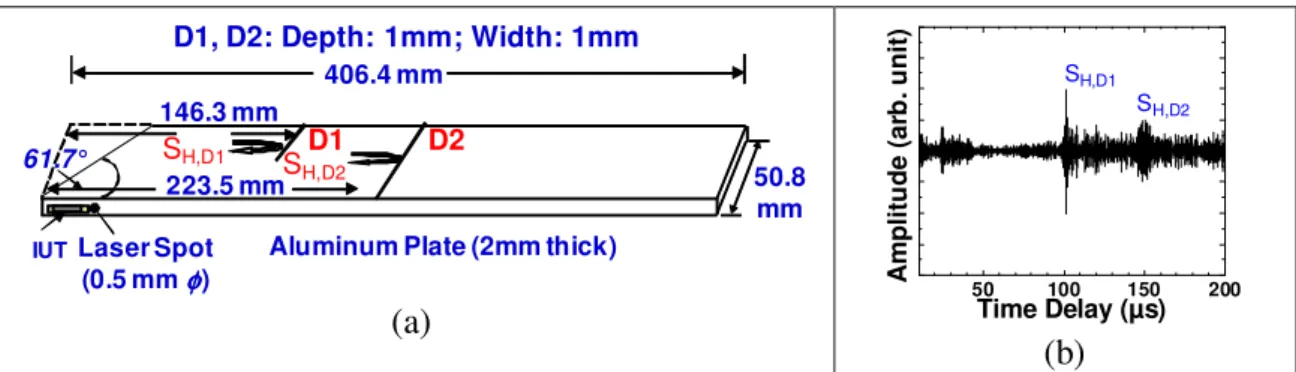
146.3 mm 223.5 mm Laser Spot (0.5 mm φφφφ) D1 D2 D1, D2: Depth: 1mm; Width: 1mm SH,D1 S H,D2 (a) 50 100 150 200 A m p li tu d e ( a rb . u n it ) Time Delay (µs) SH,D1 SH,D2 (b)
Figure 6. a) Sample and measurement arrangement for SH PAWs; (b) Measured ultrasonic signals at room temperature.
An IUT made of 90µ m thick PZT/PZT composite with a top electrode area of 1.6mm in height and 20mm in length as the receiver is coated onto the side near the edge of a 2mm thick, 50.8mm wide and 406.4mm long Al plate as shown in Figure 6a. Two artificial line defects, D1 and D2 with 1mm depth and 1mm width were also made for the demonstration of the ability of SH PAW to detect such defects in a long distance.
D1 and D2 have width of 25.4 mm and 50.8 mm, respectively. Figure 6b presents the IUT received ultrasonic signals at room temperature that generated by the same laser described in Section 3 but with pulses of 4.1mJ energy and spot size of 0.5mm diameter. The laser generation spot is at the edge beside the IUT. The laser generated L waves are mode converted [14,15] into SH PAWs waves. They are reflected by the D1 and D2 defects and received by IUT. The mode conversion angle θ is 61.7° [15]. SH,D1 and
SH,D2 are the reflected echoes from the defects D1 and D2, respectively. The centre
frequencies of the received SH,D1 and SH,D1 echoes are 3.3MHz and 3.5MHz,
respectively. Figures 6a and 6b show that IUT can be used to receive laser generated and mode converted SH PAWs for the defect detection.
5. Conclusions
IUTs made of thick (>50µ m) piezoelectric PZT/PZT or BIT/PZT films have been deposited directly onto metal substrates as receivers to detect the laser generated ultrasound up to 400°C. The film fabrication is based on a sol-gel spray technique. IUTs intrinsically acting as bulk L wave receivers used various mode conversion approaches [14,15] and served as L, S, symmetric, anti-symmetric and SH PAW receivers. The high sensitivity of IUTs allows the use of low energy (50µJ) high repetition (1kHz) pulsed lasers to produce ultrasonic signals of high SNR. Steel, SS and Al having different sizes, shapes including curved surfaces and thicknesses have been used as substrates. Different laser generation conditions such as different spot sizes, pulse durations and energy were also applied to investigate the capabilities of IUT receivers. When IUTs are used just as receivers, the required electric power is minimum and thus battery or harvested energy driven methods including wireless networks are feasible.
References
1. R.M. White, ‘Generation of elastic waves by transient surface heating’, J. Appl.
Physics, 34, pp 3559-3567, 1963.
2. C.B. Scruby, R.J. Dewhurst, D.A. Hutchins and S.B. Palmer, ‘Laser generation of ultrasound in metals’, in Res. Techniques in Nondestructrive Testing, 5, R.S. Sharpe, Ed. New York: Academic Press pp 281-327, 1982.
3. D.A. Hutchings, ‘Ultrasonic generation by pulsed lasers’, in Physics Acoustics, 18, W.P. Mason and R.N. Thurston, Ed. New York: Academic Press, pp 21-123, 1988. 4. R. Adler, A. Korpel and P. Desmares, ‘An instrument for making surface waves
visible’, IEEE Trans. Sonics Ultrason., 15, pp 157-161, 1968.
5. L.W. Kessler, P.R. Palermo and A. Korpel, ‘Recent developments with the scanning laser acoustic microscope’, in Acoustic Holography, P.S. Green, Ed., New York: Plenum Press, pp 15-23, 1974.
6. J.-P. Monchalin, ‘Optical detection of ultrasound’, IEEE Trans. Ultrason.
Ferroelect. Freq. Control, 33, pp 485-499, 1986.
7. J.W. Wagner, ‘Optical detection of ultrasound’, in Physics Acoustics, 19, W.P. Mason and R.N. Thurston, Ed. New York: Academic Press, pp 201-264, 1990. 8. R.K. Ing and J.-P. Monchalin, ‘Broadband optical detection of ultrasound by
two-wave mixing in a photorefractive crystal’, Appl. Phys. Lett., 59, pp 3233-5, 1991. 9. D.A. Hutchins and D.E. Wilkins, ‘Elastic waveforms using laser generation and
electromagnetic acoustic transducer detection’, J. Appl. Phys., 58, pp 2469-2477, 1985.
10. D.W. Schindel and D.A. Hutchins, ‘Application of micromachined capacitance transducers in air-coupled ultrasonics and non-destructive evaluation’, IEEE Trans.
Ultrason. Ferroelect. Freq. Control, 42, pp 51-58, 1986.
11. W.M.D. Wright, D.A. Hutchins, G. Hayward and A. Gachagan, ‘Ultrasonic imaging using laser generation and piezoelectric air-coupled detection’,
Ultrasonics, 34, pp 405-409, 1996.
12. D. Barrow, T.E. Petroff, R.P. Tandon and M. Sayer, ‘Chracterization of thick lead-zirconate titanate films fabricated using a new sol gel process’ J. Apply. Phys., 81, pp 876-881, 1997
13. M. Kobayashi and C.-K. Jen, ‘Piezoelectric thick bismuth titanate/PZT composite film transducers for smart NDE of metals’, Smart Materials and Structures, 13, pp 951-956, 2004.
14. C.-K. Jen and M. Kobayashi, ‘Integrated and flexible high temperature piezoelectric ultrasonic transducers’, Chapter 2 in Ultrasonic and Advanced
Methods for Nondestructive Testing and Material Characterization, Ed. by C.H. Chen, World Scientific Publ., New Jersey, pp 33-55, 2007.
15. K.-T. Wu, C.-K. Jen and M. Kobayashi, “High temperature integrated plate acoustic wave transducers”, Electronics Letts., 44, pp 776-7, 2008.