Publisher’s version / Version de l'éditeur:
INCAS Bulletin, 8, 3, pp. 41-53, 2016-09-08
READ THESE TERMS AND CONDITIONS CAREFULLY BEFORE USING THIS WEBSITE. https://nrc-publications.canada.ca/eng/copyright
Vous avez des questions? Nous pouvons vous aider. Pour communiquer directement avec un auteur, consultez la première page de la revue dans laquelle son article a été publié afin de trouver ses coordonnées. Si vous n’arrivez pas à les repérer, communiquez avec nous à [email protected].
Questions? Contact the NRC Publications Archive team at
[email protected]. If you wish to email the authors directly, please see the first page of the publication for their contact information.
Archives des publications du CNRC
This publication could be one of several versions: author’s original, accepted manuscript or the publisher’s version. / La version de cette publication peut être l’une des suivantes : la version prépublication de l’auteur, la version acceptée du manuscrit ou la version de l’éditeur.
For the publisher’s version, please access the DOI link below./ Pour consulter la version de l’éditeur, utilisez le lien DOI ci-dessous.
https://doi.org/10.13111/2066-8201.2016.8.3.4
Access and use of this website and the material on it are subject to the Terms and Conditions set forth at
Morphing wing-tip open loop controller and its validation during wind
tunnel tests at the IAR-NRC
Mohamed sadok, Guezguez; Ruxandra mihaela, Botez; Mahmoud, Mamou;
Youssef, Mebarki
https://publications-cnrc.canada.ca/fra/droits
L’accès à ce site Web et l’utilisation de son contenu sont assujettis aux conditions présentées dans le site LISEZ CES CONDITIONS ATTENTIVEMENT AVANT D’UTILISER CE SITE WEB.
NRC Publications Record / Notice d'Archives des publications de CNRC: https://nrc-publications.canada.ca/eng/view/object/?id=f552a752-f66a-4707-8e41-393fec44d017 https://publications-cnrc.canada.ca/fra/voir/objet/?id=f552a752-f66a-4707-8e41-393fec44d017
Validation During Wind Tunnel Tests at the IAR-NRC
Mohamed Sadok GUEZGUEZ
1, Ruxandra Mihaela BOTEZ*
,1,
Mahmoud MAMOU
2, Youssef MEBARKI
2*Corresponding author
1
ETS, University of Quebec, Laboratory of Applied Research in Active Controls,
Avionics and AeroServoElasticity LARCASE (www.larcase.etsmtl.ca),
1100 Notre Dame West, Montreal, Que., Canada, H3C1K3
[email protected]; [email protected]*
2
Aerodynamics Laboratory, National Research Council NRC Aerospace,
Ottawa, Ont., Canada, K1A0R6
[email protected], [email protected]
DOI: 10.13111/2066-8201.2016.8.3.4
Received: 27 June 2016/ Accepted: 29 July 2016/ Published: September 2016
© Copyright 2016, INCAS. This is an open access article under the CC BY-NC-ND license (http://creativecommons.org/licenses/by-nc-nd/4.0/)
Abstract: In this project, a wing tip of a real aircraft was designed and manufactured. This wing tip was composed of a wing and an aileron. The wing was equipped with a composite skin on its upper surface. This skin changed its shape (morphed) by use of 4 electrical in-house developed actuators and 32 pressure sensors. These pressure sensors measure the pressures, and further the loads on the wing upper surface. Thus, the upper surface of the wing was morphed using these actuators with the aim to improve the aerodynamic performances of the wing-tip. Two types of ailerons were designed and manufactured: one aileron is rigid (non-morphed) and one morphing aileron. This morphing aileron can change its shape also for the aerodynamic performances improvement. The morphing wing-tip internal structure is designed and manufactured, and is presented firstly in the paper. Then, the modern communication and control hardware are presented for the entire morphing wing tip equipped with actuators and sensors having the aim to morph the wing. The calibration procedure of the wing tip is further presented, followed by the open loop controller results obtained during wind tunnel tests. Various methodologies of open loop control are presented in this paper, and results obtained were obtained and validated experimentally through wind tunnel tests.
Key Words: morphing wing; wind tunnel tests; open loop controller; communication hardware; electrical actuators; pressure kulite sensors
1. INTRODUCTION
In this paper, the open loop control, communication and calibration studies and testing of a morphing wing-tip system are presented.
This integration was realized in the frame of the multidisciplinary CRIAQ (Consortium of Research in Quebec Aerospace Industries) MDO 505 project.
The CRIAQ MDO-505 international project was realized at the ETS between Canadian and Italian teams.
This project has been funded by Bombardier Aerospace and Thales, CRIAQ and the Natural Sciences and Engineering Research Council of Canada (NSERC).
The Canadian teams came from Aerospace industries such as Bombardier Aerospace and Thales, from the research institute IAR-NRC, and from Ecole Polytechnique. The Italian teams came from Alenia, CIRA, and University Frederico II from Naples.
In the CRIAQ MDO 505 project, research was done on a real industrial aircraft wing tip that was equipped with kulite pressure sensors, and electrical in-house actuators.
This project was a continuation of a previous CRIAQ MDO 7.1 project in which research was performed on a wing box equipped with kulite pressure sensors, and smart material actuators.
In the previous CRIAQ 7.1 project, various methodologies for a laminar to turbulent flow transition controller were designed, and further tested and validated in the Wind Tunnel
at the IAR-NRC on this wing box. These methodologies were described inRefs 1-16.
While in the former CRIAQ 7.1 project, no real wing was considered (and only a concept of a morphing wing was studied, thus no structural constraints were present), in the CRIAQ MDO 505 project a real wing demonstrator was considered for an existing aircraft, that had the real dimensions and real life structural constraints of a real wing tip, thus it was designed under real-life structural constraints.
This wing tip consisted of a wing and an aileron. Two main cases were considered for the design and testing of the morphing phenomena: a morphing wing and a rigid conventional aileron; and a morphing wing and a morphing aileron.
2. DESCRIPTION OF THE TECHNICAL DEMONSTRATOR
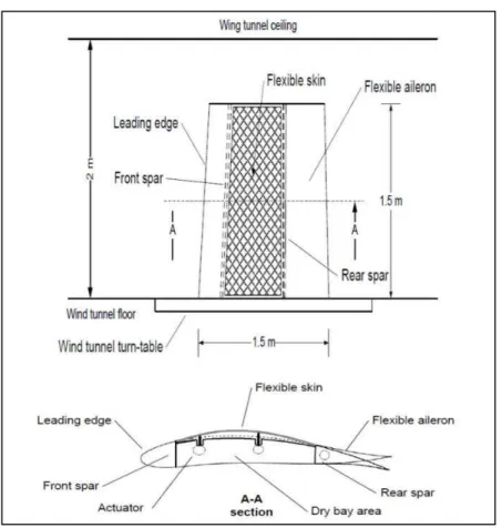
The technical demonstrator of a real industrial aircraft wing tip (wing and aileron) is shown in Figure 1.
The internal structure and the dimensions of his wing tip are realistic, as they were provided by industrial partners.
In addition, its dimensions were chosen to fit also the dimensions of the IAR-NRC subsonic wind tunnel space and force balance limitations.
The main dimensions are the root chord of 1.5 m and the tip chord of 1.08 m. As seen in Figure 1, the wing is equipped with a flexible skin manufactured in carbon fibre reinforced composite, that is delimited by its front and rear spars.
The difference between the non-morphed and morphed wing and aileron configurations could be seen on Section A-A of Figure 1.
The upper skin of the wing is equipped with two rows of pressure kulite sensors. Each row contains 16 ‘kulite’ sensors.
One row is situated on the chord-wise direction at 600 mm, while the other row is situated on the chord-wise direction at 625 mm measured from the wing tip.
These kulite sensors measure the pressure distribution, as well as the flow transition from laminar to turbulent flow.
On the rest of the wing tip model, such as the wing leading edge, its inner surface and the aileron, pressure taps were installed with the aim to measure pressures on the wing.
Four axial actuators were placed inside the wing box, as seen on Figure 2. These actuators were on the two central ribs.
Each actuator moved in both directions (up and down), and was equipped with a piston that was also attached to the upper skin from the wing inside. Each piston was linked to a lead screw.
Figure 1. Structure of the Wing and Aileron (Wing-Tip)
The screw translated the turning motion of a gearbox into a linear motion. Brushless DC motors moved the gears inside the actuator mechanism and allowed the piston to move linearly. The piston was monitored using a Linear Variable Differential Transformer (LVDT) sensor. This LVDT was used to give an accurate measurement of the skin displacement. This position sensor was fixed in parallel with the piston, and its tip was linked to the piston, so that their motion was synchronized. Thus, the skin shape changed using four actuators displacements. In this paper, the entire controller system architecture, software and hardware is presented for the morphing wing-tip.
The wing upper skin was morphed with the main aim to delay the flow transition, thus the laminar to turbulent flow transition.
In this way, the aerodynamic performances of the prototype were improved considerably. The demonstrator was further operated and controlled during Wind Tunnel Tests for a high number of cases (more than 100) by use of the sophisticated and high-performance control and monitoring system that is here explained.
3. COMMUNICATION HARDWARE
The embedded real time controller PXI-e 8135 bought from National Instruments® was the
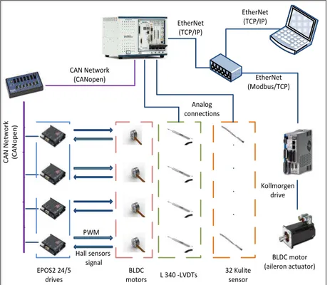
main piece of the system here described. The controller was running a real time operating system, and was connected to system hardware peripherals through several input and output modules, as seen on Figure 3.
This controller was monitored by the Host PC via an Ethernet network using the TCP/IP communication protocol, as a static IP address was used that could be personalized and fixed by the system operator.
The windows machine (the Host) was used for the control program deployment, system state control, and data monitoring in real time.
EPOS2 24/5 drives Hall sensors signal C A N N e tw o rk (C A N o p e n ) EtherNet (TCP/IP) EtherNet (TCP/IP) EtherNet (Modbus/TCP) PWM L 340 -LVDTs 32 Kulite sensor BLDC motors CAN Network (CANopen) Analog connections Kollmorgen drive BLDC motor (aileron actuator)
Figure 3. Morphing Wing Control and Communication System
The modular hardware architecture of NI systems has made our task easier, as it afforded a way to connect several wing peripherals with different I/O signals to the control unit. It was possible to process the data from 32 pressure channels sampled at 20 KHz and 4 analog LVDT sensor signals, as well as to manage a CAN-based network with four field devices (Epos2 drives). Useful features such as Ethernet ports helped to implement the communication with the aileron drive, so that the entire system could be monitored remotely from the control room during wind tunnel tests (Ref 23-24).
The integration of communication tools was also performed. In order to modify the skin shape of the wing, CANopen communication was established to control the motors positions based on the ‘LVDT sensors’ feedback.
The differential bus signaling of the ‘CAN’ field network makes it robust regarding EMI noise inside a wind tunnel. The ‘CANopen’ application layer allowed high configuration flexibility, offering the ability to program devices by choosing a specific performing mode, and by mapping the drive parameters for real time data broadcasting, that was the basis of the subsequent position closed loop.
The Modbus TCP protocol was easy to use as it did not require a special interface to physically connect to the PXI-e controller. Using motion tasks with the aileron position control has greatly simplified the protocol implementation, which was based on elementary read/write operations on Modbus registers.
4. CALIBRATION PROCEDURE
After setting up the communication mechanisms, it was unrealistic to maintain the position that a simple open loop command would be sufficient to obtain accurate skin displacement control. After the starting of the skin shape control operations, several issues began to appear. The first (and quite major) issue concerned that the skin displacement was not matching the desired input value. Several tests led us to better understand the actuator response, which was nonlinear and not repeatable (uncertain reference point); we concluded that some mechanical issues (play in the gearbox, linkage between components) were the main causes.
Problems such as ‘dead zone nonlinearity’ and ‘uncertain reference point’ were solved by using a closed position control loop based on LVDT sensor feedback. The PID controller was tuned using the ‘Hardware in Loop’ (HIL) approach; the ‘inline gains’ were tuned until the optimal actuator response was obtained.
The use of the closed loop strategy made possible the indirect control of the skin displacement with a level of efficiency and reliability. Using look-up tables to determine the relationship between skin displacements and their corresponding LVDT indications was not practical and had, also, poor precision.
The calibration procedure was further adopted to determine the LVDT values required to match desired skin displacements. Based on data sets of the desired skin displacement values for each flight case it was possible to retrieve the LVDT set point values for actuator displacements.
Automating the procedure made it easy to run and much less time consuming, especially in the wind tunnel environment.
The efficiency and the robustness of the developed communication and control methods were investigated during the bench tests at the ETS firstly in the absence of aerodynamic loads. The wind tunnel tests proved that we could operate the wing control system directly, and closely monitor the tests’ progress during two campaigns. We achieved our goal regarding control and integration, as we did not have any kind of communication failure or control instability.
The control results and more precisely, the static errors on each actuator for the position control loop will be also given in details. Globally, errors were found to be within the desired limits. In certain cases, errors exceeded the limit (only during calibration), but it was easy to repeat them given the flexibility of the calibration procedure. We present here results of the research for the wind tunnel tests validation of the numerical results.
5. WING SKIN MORPHING IN OPEN LOOP
The mechanism used to morph the skin is essentially composed of two parts: 1. the actuation mechanism (which contains the BLDC, gear box, lead screw and piston) and 2. the actuator displacement sensor (LVDT).
When designing this mechanism it was thought that skin displacement would be linearly dependent on morphing mechanism displacement, but when we started working on the wing prototype, some unexpected problems appeared, thus making the control task more delicate and complicated.
It was believed that the desired skin displacement would be obtained by moving the actuators with the needed exact value (displacement of the piston in mm = number of motor rotations/100); in other words, by acting on each actuator in order to achieve the correct number of rotations.
However, when applying an input command to each actuator, the LVDT indication did not match either its desired value or the real skin displacement.
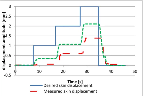
Figure shows the skin response (represented by a ‘continuous line’) after applying an
input command to the first actuator. Measurements on both LVDT and on the skin are represented on this figure, as well as the desired input command.
The graph shows that the measured LVDT indications are always smaller than the desired values.
This offset between the actuator position (motor angle) and the ‘LVDT indication’ may be caused by the mechanical play inside the actuator mechanism and the difference between the desired and measured displacement on LVDT constitutes the compensation for this mechanical slack.
The second issue is that the ‘measured skin displacement’ above the actuation point is also smaller to the desired displacement and the LVDT measured value. Possible explanations are that the wing structure (ribs, spars…) is not perfectly rigid but somewhat elastic and intern interactions between the skin and actuators; therefore, a displacement of 2 mm of the worm and wheel gears will not be entirely transmitted to the skin. Otherwise, the lower wing skin would be slightly changed.
Figure 4. Skin response with open loop position control
-0,5 0 0,5 1 1,5 2 2,5 3 0 10 20 30 40 50 d isp lac e m e n t am p li tu d e [m m ] Time [s] Desired skin displacement Measured skin displacement
Another issue is that the non-morphed position is not well defined and there is no reference that indicates the zero displacement point. In fact, when mounting the actuator inside the wing, each actuator should have its piston near the half-travel position and this position will be considered as zero displacement position.
LVDTs should be placed so as to show almost zero mm of displacement; however, once we began moving the actuators, we noticed that the same input command with two different signs (e.g., +1 mm then -1 mm) did not bring the mechanism back to its initial position (based on LVDT indication). Also, since the motors are controlled by electronic drives, it is not possible to save the actual position of the motor when the drive is turned off or restarted (the actual position value will be lost).
Given all of the above issues, we started thinking about using LVDT indication as a reference for the displacement of each actuator. In fact, unlike the electronic drive, LVDT has the advantage of retaining the measured value even when not excited (turned off), so it could be used as a reference for measuring the actuator stroke.
Noticing that there was a difference between the input command and the measured deflection of the skin, we tried to establish a correlation between the measured deflection of the skin and the indicated displacement value on LVDT. The idea was to represent the variation of the skin displacement versus LVDT indication in relationship to the zero deflection value of the skin. This representation would help to analyze and better understand the mechanical behavior of the entire system.
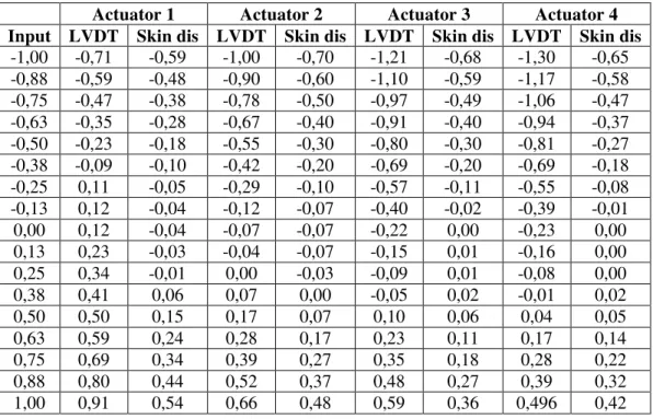
Table 1. Measurements (in mm) used to determine actuator offset values
Actuator 1 Actuator 2 Actuator 3 Actuator 4
Input LVDT Skin dis LVDT Skin dis LVDT Skin dis LVDT Skin dis
-1,00 -0,71 -0,59 -1,00 -0,70 -1,21 -0,68 -1,30 -0,65 -0,88 -0,59 -0,48 -0,90 -0,60 -1,10 -0,59 -1,17 -0,58 -0,75 -0,47 -0,38 -0,78 -0,50 -0,97 -0,49 -1,06 -0,47 -0,63 -0,35 -0,28 -0,67 -0,40 -0,91 -0,40 -0,94 -0,37 -0,50 -0,23 -0,18 -0,55 -0,30 -0,80 -0,30 -0,81 -0,27 -0,38 -0,09 -0,10 -0,42 -0,20 -0,69 -0,20 -0,69 -0,18 -0,25 0,11 -0,05 -0,29 -0,10 -0,57 -0,11 -0,55 -0,08 -0,13 0,12 -0,04 -0,12 -0,07 -0,40 -0,02 -0,39 -0,01 0,00 0,12 -0,04 -0,07 -0,07 -0,22 0,00 -0,23 0,00 0,13 0,23 -0,03 -0,04 -0,07 -0,15 0,01 -0,16 0,00 0,25 0,34 -0,01 0,00 -0,03 -0,09 0,01 -0,08 0,00 0,38 0,41 0,06 0,07 0,00 -0,05 0,02 -0,01 0,02 0,50 0,50 0,15 0,17 0,07 0,10 0,06 0,04 0,05 0,63 0,59 0,24 0,28 0,17 0,23 0,11 0,17 0,14 0,75 0,69 0,34 0,39 0,27 0,35 0,18 0,28 0,22 0,88 0,80 0,44 0,52 0,37 0,48 0,27 0,39 0,32 1,00 0,91 0,54 0,66 0,48 0,59 0,36 0,496 0,42
The operation consists of separately moving each actuator with a small step between -1 mm and +1 mm, then measuring the skin displacement and taking the LVDT indication for each point.
Table 1 shows the results of the experiment for each actuator. These measurements will be used to define the ‘dead zone’ for each actuator. Figure shows he results obtained for the first actuator, similar shapes are obtained with the other actuators.
Figure 5. Actuator ‘1’ displacement profile
In the above graph, the measured deflection is represented both on the LVDT and on the
digital dial indicator (skin displacement measurement) for the actuator ‘1’.
The curve with square marks, which represents the measured deflection on LVDT versus the desired input, shows a nonlinear behavior of the mechanism, while the graph becomes linear outside this zone. We can also see that the skin does not move for the steps between -0.25 mm and 0.3 mm on the desired input (curve with cross marks). The same type
of behavior was observed for the actuators ‘2’, ‘3’ and ‘4’.
Since the LVDT indication is the only reference that will be used for displacement control, the measured real skin displacement is plotted against LVDT indication (Figure 6) to determine the ‘dead zone’ amplitude in terms of LVDT measurement variation.
Figure 6. Skin deflection in terms of measured deflection on LVDT
-0,8 -0,6 -0,4 -0,2 0 0,2 0,4 0,6 0,8 1 -1,2 -0,7 -0,2 0,3 0,8 M e a su re d d is p la ce men t [m m] Desired displacement [mm]
Measured deflection on LVDT Measured deflection on the skin
-0,8 -0,6 -0,4 -0,2 0 0,2 0,4 0,6 -1,5 -1 -0,5 0 0,5 1 1,5 Re a l skin d e fe cti o n [m m] LVDT measurement [mm]
As we can see, the curve (with cross marks) shows “a dead zone nonlinearity”; in other words, the skin doesn’t move during a certain range of values on the LVDT, indicating that the actuator is rotating but not producing the desired effect on the skin.
Outside this range, the actuator is tight to the skin and the graph becomes almost linear.
The ‘middle of the dead zone’ will be considered as a reference position and an offset value
(half of the dead zone amplitude) will be considered for each LVDT channel; in this way, our reference position will be 0 mm of displacement on each LVDT. For this value, actuator mechanisms are in the middle of the ‘dead zone, ensuring that the skin is not morphed at all (graph with circle marks).
The zero mm on LVDT should correspond to a null displacement value of the skin, which is not the case in the graphic (Figure 6); the problem is just a zero set issue on the digital dial indicator.
The same operation was performed using the remaining actuators by allowing us to resolve some of the noted critical issues. This preliminary “calibration” is very important at this step and will help us to achieve our primary goal of morphing the wing.
The next step is to identify how to control the wing based on the measurement feedback from the LVDT value, since this measurement is the absolute reference for defining the real shape of the flexible skin.
6. RESULTS OF WIND TUNNEL TESTS CALIBRATION
For the first set of wind tunnel tests, only 38 optimized shapes were planned for testing purposes. Calibration took place after installing the wing model inside the wind tunnel at the IAR-NRC in order to obtain accurate calibration measurements.
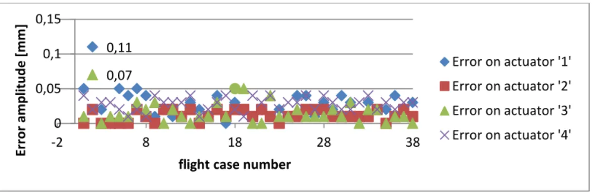
Figure 7. Errors obtained during the wind tunnel tests calibration of four actuators
Figure 7 shows the errors of the calibration procedure; these errors correspond to the differences between desired and measured displacement values obtained for the actuators. The errors are calculated separately for each actuator. As shown on Figure 7, an error
exceeding 0.1 mm of amplitude was obtained for flight case number 2 for actuators ‘1’ and
‘3’. This error was unacceptable within the fixed criteria, so that this flight case was repeated separately for more precision. For the rest of flight cases, results were overall acceptable, since errors were smaller or equal to 0.05 mm.
Because of the fact that Digital Dial Indicators could not be used to measure skin displacements in the presence of the winds, the accuracy of skin shapes compared to the desired ones were verified by comparison of the obtained LVDTs values during aerodynamic tests, with the LVDTs values during calibration (which were used as set points during aerodynamic tests). 0,11 0,07 0 0,05 0,1 0,15 -2 8 18 28 38 E rr o r am p li tu d e [ m m ]
flight case number
Error on actuator '1' Error on actuator '2' Error on actuator '3' Error on actuator '4'
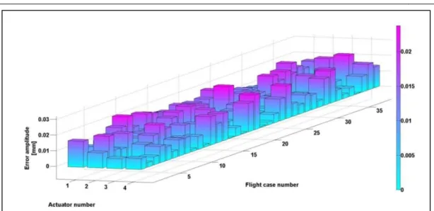
Figure 8. Displacements Errors Amplitudes measured on LVDTs during Wind Tunnel Tests
In Figure 8, displacement errors distribution were shown for each actuator, and for each flight case. For all 38 flight cases, and for all 4 actuators, the error remained smaller than 0.03 mm. This error level was ensured when added to calibration error, since cumulative error would not exceed the level of 0.8 mm in the worst case.
During the second set of wind tunnel tests, 97 flight cases were considered, since several aerodynamic optimized configurations were added to verify the accuracy of the comparison between numerical and experimental results. The aerodynamic performances were presented and discussed by the aerodynamic team for the first and second sets of wind tunnel tests in Refs. 17-22. The pie chart shows the percentage breakdown of errors obtained during the calibration procedure for each actuator in Figure 9.
Figure 9. Calibration error percentages for the 4 actuators
92% 7% 1%
Actuator '1'
error < 0.03 mm 0.0 ≤ error ≤ 0.0 mm 0.04 mm < error 97% 3%Actuator '2'
error < 0.03 mm 0.0 ≤ error ≤ 0.0 mm 0.04 mm < error 94% 5% 1%Actuator '3'
error < 0.03 mm 0.0 ≤ error ≤ 0.0 mm 0.04 mm < error 64% 36%Actuator '4'
error < 0.03 mm 0.0 ≤ error ≤ 0.0 mm 0.04 mm < errorThe calculated absolute error shown above is the difference between the desired skin displacement value and the displacement value measured during calibration. Error exceeds 0.04 mm of amplitude in only one flight case, number two, where errors were 0.08 mm and 0.06 mm respectively, on the first and third actuators.
The flight case was recalibrated in order to obtain acceptable error amplitude (generally a value lower than 0.05 mm) and an error of 0.03 mm was obtained.
For the rest of the flight cases, the error did not exceed 0.04 mm of amplitude for all actuators as seen on Figure 9.
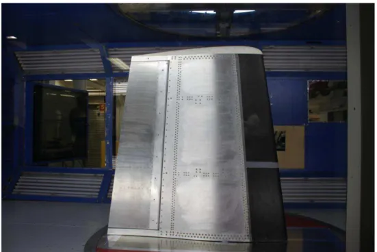
As previously mentioned, the wind tunnel tests took place at the Institute of Aerospace Research (IAR)-National Research Council (NRC) subsonic wind tunnel in Ottawa, Ontario, Canada.
The closed circuit wind tunnel had a square testing chamber with cut corners. The test
section dimensions are 2.74 x 4.5 x 1.93 (H x L X W) and the section area is 5.04 m2. The
longitudinal static pressure is zero and the measured flow turbulence level is 0.14%. The wing model is shown as installed in the IAR-NRC wind tunnel in Figure 10.
Figure 10. Wing model installed in the IAR-NRC subsonic wind tunnel
7. CONCLUSIONS
In this work, results obtained for the open loop procedure of the morphing wing skin were presented for a morphing wing tip.
The modular hardware architecture of NI systems has afforded a simple way to connect several wing peripherals with different I/O signals to the control unit. It was possible to process the data from 32 pressure channels sampled at 20 KHz and four analog LVDT sensor signals, as well as to manage a CAN-based network with four field devices (Epos2 drives). Useful features such as Ethernet ports helped to implement the communication with the aileron drive, so that the entire system could be monitored remotely from the control room during wind tunnel tests.
The calibration procedure was further adopted to determine the LVDT values required to match desired skin displacements.
Based on data sets of the desired skin displacement values for each flight case it was possible to retrieve the LVDT set point values for actuator displacements. Automating the procedure made it easy to run and much less time consuming, especially in the wind tunnel environment. More details can be found in Refs. 25-30.
ACKNOWLEDGEMENTS
The authors would like to thank the Thales Avionics team for their support - especially Mr. Philippe Molaret, Mr. Bernard Blouin, and Mr. Xavier Louis, as well as the Bombardier Aerospace team, Mr. Patrick Germain and Mr. Fassi Kafyeke in particular.
We would also like to thank the Consortium for Research and Innovation in Aerospace in Quebec (CRIAQ) and the National Sciences and Engineering Research Council (NSERC) for their funding of the CRIAQ MDO 505 project.
REFERENCES
[1] L. T. Grigorie, R. M. Botez, Modeling and simulation based Matlab/Simulink of a strap down inertial
navigation system’ errors due to the inertial sensors, In book: MATLAB Applications for the Practical
Engineer, pp. 1-34, INTECH Edition, 2014.
[2] L. T. Grigorie, R. M. Botez, A. V. Popov, Fuzzy logic control of a smart actuation system in a morphing
wing, In book: Fuzzy Controllers – Recent Advances in Theory and Applications, pp. 1-22, ISBN:
979-953-307-843-3, INTECH Edition, 2012.
[3] L. T. Grigorie, R. M. Botez, Applications of fuzzy logic in the design and control of a morphing wing using
smart material actuators, Fuzzy Controllers, Theory and Applications, pp. 253-296, INTECH Edition,
2011.
[4] L. T. Grigorie, A. V. Popov, R. M. Botez, M. Mamou, Y. Mébarki, Design and experimental validation of a combined PI and bi-positional laws controller for delaying the transition from laminar flow to turbulent flow over a morphing wing, Vol. 89, pp. 51-76, Informatics in Control, Automation and Robotics, Lecture Notes in Electrical Engineering, Springer-Verlag Edition, 2011.
[5] A. V. Popov, R. M. Botez, L. T. Grigorie, M. Mamou, Y. Mebarki, Modeling and Testing of a Morphing Wing in an Open Loop Architecture, AIAA Journal of Aircraft, Vol. 47(3), pp. 917-923, 2010.
[6] L. T. Grigorie, A.-V. Popov, R. M. Botez, M. Mamou, Y. Mebarki, On-Off and Proportional-Integral Controller for a Morphing Wing. Part 1: actuation mechanism and control design, Proceedings of the
Institution of Mechanical Engineers, Part G, Journal of Aerospace Engineering, Vol. 226(2), pp.
131-145, 2011.
[7] L. T. Grigorie, A.-V. Popov, R. M. Botez, M. Mamou, Y. Mebarki, On-Off and Proportional-Integral Controller for a Morphing Wing. Part 2: control validation - numerical simulations and experimental tests, Proceedings of the Institution of Mechanical Engineers, Part G, Journal of Aerospace Engineering, Vol. 226(2), pp. 146-162, 2011.
[8] L. T. Grigorie, R. M. Botez, A. V. Popov, M. Mamou, Y. Mébarki, A Hybrid Fuzzy Logic Proportional-Integral-Derivative and Conventional On-Off Controller for Morphing Wing Actuation using Shape Memory Alloy, Part 1: Morphing System Mechanisms and Controller Architecture Design, The
Aeronautical Journal, Vol. 116 (1179), pp. 433-449, 2012.
[9] L. T. Grigorie, R. M. Botez, A. V. Popov, M. Mamou, Y. Mébarki, A Hybrid Fuzzy Logic Proportional-Integral-Derivative and Conventional On-Off Controller for Morphing Wing Actuation using Shape Memory Alloy, Part 2: Controller Implementation and Validation, The Aeronautical Journal, Vol. 116 (1179), pp. 451-465, 2012.
[10] L. T. Grigorie, R. M. Botez, A.-V. Popov, How the Airfoil Shape of a Morphing Wing is Actuated and Controlled in a Smart Way, The Journal of Aircraft Engineering, ASCE Edition, Vol. 28(1), 2015. [11] A. V. Popov, R. M. Botez, T. L. Grigorie, M. Mamou, Y. Mebarki, Real Time Morphing Wing Optimization
[12] L. T. Grigorie, R. M. Botez, A.-V. Popov, Adaptive Neuro-Fuzzy Controllers for an Open Loop Morphing Wing System, Proceedings of the Institution of Mechanical Engineers - Part G: Journal of Aerospace
Engineering, Vol. 223(J), pp. 965-975, 2009.
[13] L. T. Grigorie, R. M. Botez, Adaptive Neuro-Fuzzy Interference System Based Controllers for Smart Material Actuator Modeling, Proceedings of the Institution of Mechanical Engineers - Part G: Journal of
Aerospace Engineering, Vol. 223(G6), pp. 655-668, 2009.
[14] A.-V. Popov, R. M. Botez, M. Mamou, L. T. Grigorie, Variations in Optical Sensor Pressure Measurements due to Temperature in Wind Tunnel Testing, AIAA Journal of Aircraft, Vol. 46(4), pp. 1314-1318, 2009. [15] A.-V. Popov, M. Labib, J. Fays, R. M. Botez, Closed Loop Control Simulations on a Morphing Wing, AIAA
Journal of Aircraft, Vol. 45(5), pp. 1794-1803, 2008.
[16] A. V. Popov, R. M. Botez, M. Labib, Transition Point Detection from the Surface Pressure Distribution for Controller Design, AIAA Journal of Aircraft, Vol. 45(1), pp. 23-28, 2008.
[17] O. Sugar Gabor, A. Koreanschi, R. M. Botez, M. Mamou, Y. Mébarki, Numerical Simulation and Wind Tunnel Tests Investigation and Validation of a Morphing Wing-Tip Demonstrator Aerodynamic Performance, Aerospace Science and Technology, Vol. 53, pages 136-153, June 2016.
[18] A. Koreanschi, O. Sugar-Gabor, R. M. Botez, Drag Optimization of a Wing Equipped with a Morphing Upper Surface, The Aeronautical Journal, Vol. 120(1225), pp. 473-493, doi:10.1017/aer.2016.6, 2016. [19] A. Koreanschi, M. B. Henia, O. Guillemette, F. Michaud, Y. Tondji, O. Sugar Gabor, R. M. Botez, M. Flores
Salinas, Flutter Analysis of a Morphing Wing Technology Demonstrator: Numerical Simulation and Wind Tunnel Testing, INCAS BULLETIN, March Issue, Vol. 8(1), (online) ISSN 2247–4528, (print) ISSN 2066–8201, ISSN–L 2066–8201, DOI: 10.13111/2066-8201.2016.8.1.10, pp. 99-124, 2016. [20] O. Sugar Gabor, A. Koreanschi, R. M. Botez, M. Mamou, Y. Mebarki, Analysis of the Aerodynamic
Performance of a Morphing Wing-Tip Demonstrator Using a Novel Nonlinear Vortex Lattice Method,
34th AIAA Applied Aerodynamics Conference, AIAA Aviation, Washington, DC, USA, June 13-17, 2016.
[21] A. Koreanschi, O. Sugar Gabor, J. Acotto, R. M. Botez, M. Mamou, Y. Mébarki, A Genetic Algorithm
Optimization Method for a Morphing Wing Tip Demonstrator Validated Using Infra-Red Experimental Data, 34th AIAA Applied Aerodynamics Conference, AIAA Aviation, Washington, DC, USA, June 13-17, 2016.
[22] A. Koreanschi, O. Sugar Gabor, T. Ayrault, R. M. Botez, M. Mamou, Y. Mébarki, Numerical Optimization
and Experimental Testing of a Morphing Wing with Aileron System, AIAA SciTech 2016, San Diego,
CA, January 4-8, 2016.
[23] O. P. A. Ayre et Ch. Keydel, Embedded Networking with CAN and CANopen The United States of America: RTC Books, 2003.
[24] * * * CAN in automation, 301 V4. 2.0–CANopen application layer and communication profile, CAN in Automation V4. 2.0, 2011.
[25] M. Guezguez, Morphing Wing System Integration with Wind Tunnel Testing, Master Thesis, ETS, 2016. [26] M. J. Tchatchueng Kammegne, L. T. Grigorie, R. M. Botez, Design, Numerical Simulation and
Experimental Testing of a Controlled Electrical Actuation System in a Real Aircraft Morphing Wing Model, The Aeronautical Journal, Vol. 119(1219), 2015.
[27] M. J. Tchatchueng Kammegne, R. M. Botez, L. Grigorie, M. Mamou, Y. Mebarki, A Wind Tunnel tested
Control System for a Morphing Wing Actuation Mechanism, AIAA Atmospheric Flight Mechanics
Conference, Washington, DC, USA, June 13-17, 2016.
[28] M. J. Tchatchueng Kammegne, R. M. Botez, T. L. Grigorie, M. Mamou, Y. Mébarki, Aircraft Energy
Consumption Limitation through Drag Reduction based on Morphing Wing Technology – A New Multidisciplinary Experimental Model, The 6th International Conference & Workshop REMOO-2016, Budva, Montenegro, May 18-20, 2016.
[29] M. J. Tchatchueng Kammegne, R. M. Botez, T. L. Grigorie, Actuation Mechanism Control in a Morphing
Application with a Full Scaled Portion of an Aircraft Wing, IASTED Modelling, Identification and
Control Conference, Innsbruck, Austria, February 16-17, 2016.
[30] A. Koreanschi, O. Sugar Gabor, T. Ayrault, R. M. Botez, M. Mamou, Y. Mébarki, Numerical Optimization
and Experimental Testing of a Morphing Wing with Aileron System, AIAA SciTech 2016, San Diego,
![Figure 6. Skin deflection in terms of measured deflection on LVDT -0,8-0,6-0,4-0,200,20,40,60,81-1,2-0,7-0,20,3 0,8Measured displacement [mm]Desired displacement [mm]](https://thumb-eu.123doks.com/thumbv2/123doknet/14077255.463187/9.744.106.639.649.968/figure-deflection-measured-deflection-measured-displacement-desired-displacement.webp)