Publisher’s version / Version de l'éditeur:
Journal of Thermal Spray Technology, 19, 4, pp. 787-795, 2010-06-01
READ THESE TERMS AND CONDITIONS CAREFULLY BEFORE USING THIS WEBSITE. https://nrc-publications.canada.ca/eng/copyright
Vous avez des questions? Nous pouvons vous aider. Pour communiquer directement avec un auteur, consultez la première page de la revue dans laquelle son article a été publié afin de trouver ses coordonnées. Si vous n’arrivez pas à les repérer, communiquez avec nous à PublicationsArchive-ArchivesPublications@nrc-cnrc.gc.ca.
Questions? Contact the NRC Publications Archive team at
PublicationsArchive-ArchivesPublications@nrc-cnrc.gc.ca. If you wish to email the authors directly, please see the first page of the publication for their contact information.
NRC Publications Archive
Archives des publications du CNRC
This publication could be one of several versions: author’s original, accepted manuscript or the publisher’s version. / La version de cette publication peut être l’une des suivantes : la version prépublication de l’auteur, la version acceptée du manuscrit ou la version de l’éditeur.
For the publisher’s version, please access the DOI link below./ Pour consulter la version de l’éditeur, utilisez le lien DOI ci-dessous.
https://doi.org/10.1007/s11666-009-9461-8
Access and use of this website and the material on it are subject to the Terms and Conditions set forth at
Phase formation and transformation in alumina/YSZ nanocomposite
coating deposited by suspension plasma spray process
Tarasi, F.; Medraj, M.; Dolatabadi, A.; Oberste-Berghaus, J.; Moreau, C.
https://publications-cnrc.canada.ca/fra/droits
L’accès à ce site Web et l’utilisation de son contenu sont assujettis aux conditions présentées dans le site
LISEZ CES CONDITIONS ATTENTIVEMENT AVANT D’UTILISER CE SITE WEB.
NRC Publications Record / Notice d'Archives des publications de CNRC:
https://nrc-publications.canada.ca/eng/view/object/?id=fd397904-1c36-4546-a4a3-89523df2542d https://publications-cnrc.canada.ca/fra/voir/objet/?id=fd397904-1c36-4546-a4a3-89523df2542d
Phase Formation and Transformation
in Alumina/YSZ Nanocomposite Coating
Deposited by Suspension Plasma
Spray Process
F. Tarasi, M. Medraj, A. Dolatabadi, J. Oberste-Berghaus, and C. Moreau
(Submitted July 22, 2009; in revised form August 17, 2009)
Suspension Plasma Spray process was used for deposition of pseudo-eutectic composition of alumina-yttria-stabilized zirconia as a potential thermal barrier coating using Mettech axial III torch. Process variables including feed and plasma parameters were altered to find their effects on the formation of phases in the composite coating. The in-flight particle velocity was found to be the crucial parameter on phase formation in the resulting coatings. Low particle velocities below 650 m/s result in the formation of stable phases i.e., a-alumina and tetragonal zirconia. In contrast, high particle velocities more than 750 m/s favor the metastable c-alumina and cubic zirconia phases as dominant structures in as-deposited coatings. Accordingly, the plasma auxiliary gas and plasma power as influential parameters on the particle velocity were found to be reliable tools in controlling the resulting coating structure thus, the consequent properties. The noncrystalline portion of the coatings was also studied. It was revealed that upon heating, the amorphous phase prefers to crystallize into pre-existing crystalline phases in the as-deposited coating. Thus, the ultimate crystalline structure can be designed using the parameters that control the particle velocity during plasma spray coating.
Keywords alumina/yttria-stabilized zirconia, amorphous phase, ceramic composite coating, crystalline structure, suspension plasma spray, thermal changes
1. Introduction
Alumina-zirconia coatings are being considered as potential alternative to the present thermal barrier coat-ings (TBCs). These TBCs include cubic or tetragonal zir-conia stabilized by substituting some of the Zr atoms with one or more of the base elements from alkali metal oxides such as CaO, MgO, transient metal oxides as in Y2O3, Sc2O3, Er2O3(Ref1), rare-earths such as CeO, Yb2O3, or the whole Lanthanides group (Ref 2). Stabilization is to prevent the adverse effects of the phase transformation of zirconia coatings into monoclinic structure. Alternatively, stabilization can be attained in a composite with alumina, which can further enhance its thermodynamic stability at various temperatures (Ref3), and improve its mechanical properties (Ref4) as well as thermal resistivity (Ref5).
Both zirconia and alumina, during deposition by plasma spraying, have their own phase formation prefer-ences. According to Golozar et al. (Ref 6), as-deposited yttria-stabilized zirconia (YSZ) coating applied by atmo-spheric plasma spray (APS) process shows mainly tetrag-onal along with some cubic structure. Alumina, on the other hand, presents the cubic c-crystal structure regard-less of the plasma spray technique and powder feed size (Ref 7-10). Nonetheless, some reports show that applica-tion of nanopowder feed can end up with mainly hexag-onal a-structure in conventihexag-onal plasma spray (Ref11).
During spray process of alumina-YSZ composite coat-ings, the splats may be found in at least three conditions, which include: splats formed of un-melted or partially melted feed particles, splats consisting of melted particles of either alumina or YSZ without mixing, or the blended splats composed of melted and mixed alumina-YSZ. The un-melted particles in the coating may preserve the crys-talline structure of the feed materials. The melted particles of unmixed alumina or zirconia in the coatings transform into almost the same above structures, which means that zirconia in the composite coating is reported to change from mainly monoclinic to larger amounts of tetragonal and the alumina appears as c or d (that is the transient phase before a-alumina forms out of c), using APS process (Ref 12). In addition, in quench assisted APS coating the zirconia forms tetragonal along with cubic structure, while alumina is not observed in the XRD pattern (Ref 13). Liquid injection processes, on the other hand, have pre-sented mainly tetragonal plus some cubic crystalline YSZ
F. Tarasi, M. Medraj, and A. Dolatabadi, Department of Mechanical and Industrial Engineering, S-EV 4411, Concordia University, Sir George Williams Campus, 1515 St. Catherine W., Montreal, QC, H3G 2W1, Canada; andJ. Oberste-Berghaus and C. Moreau, NRC-IMI, Boucherville, QC, Canada. Contact e-mails: f_tarasi@yahoo.com and mmedraj@encs.concordia.ca.
JTTEE5 19:787–795
DOI: 10.1007/s11666-009-9461-8 1059-9630/$19.00 Ó ASM International
Peer
and c-alumina (Ref14-17). The blended splats are strongly prone to amorphous phase formation (Ref14,18).
The process used in this study is suspension plasma spray (SPS) that is a kind of liquid injection process applied for deposition of very small particles (<5 lm) (Ref 19). These processes employ a liquid carrier for transportation of the small solid particles into the plasma torch to circumvent the difficulty in injecting such parti-cles. The problem with small particles is due to formation of large agglomerates which result in clogging the feed injection path. In SPS process, the feed liquid includes the suspension of the solid particles. The suspension droplets injected into the torch, undergo a sequence of fragmen-tation into smaller drops, evaporation of the liquid and condensation of the solid particles followed by melting. The particles with different degrees of melting, as men-tioned above, will next impact the surface and form the SPS coating (Ref20,21).
It is expected that in every process, the spray parame-ters affect the above splat conditions and can be used to vary the structure of the resulting coating and may be selected for producing-specific phases. These parameters, in addition, can influence the particle velocity and tem-perature (Ref 22). On the other hand, the amorphous content of the composite coatings will go through crys-tallization process when the coating is used at high tem-perature. The preferred phases during this process determine the final coating structure and can consequently affect the coating properties and reliability.
The purpose of this study was: to determine the influ-ential variables on the crystalline phase formation in SPS coatings of the pseudo-eutectic alumina-8 wt.% YSZ composite. In addition, it was to investigate the nature of transformations upon heating and the preferred crystalline structure during crystallization of the amorphous phases. Therefore, the feed material and plasma parameters in SPS process were varied to enable the prediction of the coating structure under each spray condition. The effects of heat treatment on the present phases were next studied from room temperature to 1500 °C to investigate the
phase transformations, as well as the preferred phases during crystallization of the amorphous phase.
2. Experimental
A group of 16 coating samples were produced on (2.5 9 2.5 9 0.5 cm3) mild steel coupons using SPS pro-cess. Powder feeds with weight ratio of 60 alumina/40 YSZ were deposited under various spray conditions.
To generate two different powder size ranges, first an 8 wt.% YSZ nanopowder was produced by mixing 5 wt.% YSZ and 13 wt.% YSZ powders with appropriate pro-portions, both with a size distribution of 30-60 nm (from Nanocomposite Powder, Inframat Advanced Materials, Farmington, CT). The resulting doped-zirconia combina-tion was then mixed with two different sizes of alumina powders. The alumina powders were either nano with a nominal size of 27-43 nm (Nanostructured and Amorphous Materials Inc., Los Alamos, NM) or micron with an average size of 1.4 lm (Baikowski Malakoff, Malakoff, TX). The resulting mixtures were called ‘‘Nano’’ and ‘‘Micron,’’ respectively.
According to the initial assessment of the x-ray dif-fraction patterns of each of these powders, the zirconia feed consists of cubic structure and the alumina nano-powder contains both rhombohedral (a) and cubic (c) structure. The ratio of a/c in the nanopowder, according to the supplier, was of about 95/5 wt.%, while the micron-size alumina powder shows only a-structure. The loose nano-and or micron-size powders after mixing were suspended in ethanol as the carrier liquid for injection of the solid feed into plasma torch. The 13 wt.% YSZ nanopowder was also deposited separately using the same process as a reference point and to investigate the preferred crystalline structure of the material without the alumina addition.
The variables studied in this work are listed in Table1. They consist of the plasma auxiliary gas, the solid con-centration in the suspension, feed rate, and the powder
Table 1 Variables evaluated for the effect on phase formation
Sample number Auxiliary gas Solid content, % Feed rate, kg/h Powder type Power, kW Vp±20, m/s Tp±50, °C
1 He 30 1.8 Nano 57 592 2880 2 He 30 1.8 Micron 57 605 2811 3 He 10 1.8 Micron 57 654 2600 4 He 30 1.3 Nano 56 638 3015 5 He 10 1.3 Nano 82 650 3030 6 H2 30 1.3 Micron 84 730 2780 7 He 30 1.3 Micron 81 788 2930 8 H2 30 1.3 Nano 118 810 3000 9 H2 10 1.3 Micron 117 814 2869 10 H2 30 1.8 Nano 118 815 2850 11 H2 10 1.8 Micron 116 840 2794 12 He 10 1.3 Micron 80 770 3100 13 H2 10 1.3 Nano 85 730 2995 14 H2 30 1.8 Micron 85 712 2740 15 He 10 1.8 Nano 82 790 3160 16 H2 10 1.8 Nano 85 718 2880
Peer
Reviewed
size range. Table1, also, indicates the plasma powers resulted from the auxiliary gas change and variation of other spray conditions detailed in Ref22. The variables were changed in two levels that can be extracted from the same table. It can be seen inTable1that the solid content have been varied from 10% to 30%, feed rate from 1.3 to 1.8 kg/h and plasma auxiliary gas has been changed from H2to He.
The resulting in-flight particle velocities and tempera-tures (reported in the last two columns of Table1) at spray distance were monitored by Accura-Spray G2 (Tecnar Automation, St. Bruno, QC, Canada) diagnostic system. Since the small particle size does not allow mea-surements of individual particles, this system that moni-tors the ensemble particle velocity and temperature was used. The substrates temperatures monitored by infrared pyrometer were constantly in the range of 350-450 °C.
For structural studies, D8 Discover x-ray diffractome-ter (Bruker Axs Inc., Madison, WI) was used in which the XRD scanned patterns can be compared with the ICSD pattern data base. The phases were analyzed based on Reitveld refinement techniques using the Powdercell program (Ref23).
For thermal analysis, the scanning mode of the Setaram thermal analysis machine model TG96 (SETARAM Inc., Newark, CA), was used with a heating and cooling rate of 5 °C per minute. This low rate allows better detection of all possible transformation. In this technique, the energy released or absorbed during temperature variations of the samples are measured based on the peak size.
The nature of the transformations was next verified through heat treatments of the coated samples at 700 °C for 12 h, 1000 °C for 1 h, and 1200 °C for 24 h. These temperatures were selected based on the transformation temperatures observed in the DSC graphs. In addition, heat treatment at 1500 °C for 5 h was done to determine the thermal stability of the composite at high tempera-tures. The heat treatments were done in air atmosphere with 200 °C per hour heating and cooling rates.
3. Results and Discussion
3.1 Crystalline Phases
The as-deposited coatings contain different phases as shown in Fig.1. Figure1(a) represents the XRD pattern of the unmixed 13 wt.% YSZ powder coating without alumina that shows a fully cubic structure. Analyzing the x-ray diffraction patterns of the composite coatings revealed that stabilized zirconia, as shown in Fig.1(a-d), basically appears as face centered cubic structure match-ing with ICSD database number 82-1246 with formula Zr0.8Y0.2O1.9. The symmetry system for this structure is (225) equivalent to Fm-3m (indicated as t00structure in the database). A second compatible pattern with the XRD of the resulting coatings was the pattern number 30-1468 with formula Y0.15Zr0.85O1.93and the same symmetry. This structure appears in both, stabilized zirconia without alu-mina and in its composite with alualu-mina. There is a small
difference between the cubic and t00 structure of zirconia. The difference is in the oxygen anions displacements within the structure (Ref1) so that in t00 structure there is a slight displacement from tetrahedral interstitial posi-tions for oxygen atoms as compared with the so-called ‘‘cubic structure.’’ In general, the dominant structure for zirconia in this experiment was mainly cubic (or t00) structure.
However, in a group of samples, a slight splitting of the peaks at about 59°-60° (related to the planes (103) and (211) of the tetragonal structure), as in Fig.2, suggests the presence of some tetragonal YSZ phase. The compatible pattern for this structure in ICSD database was the pattern number 82-1242 and Zr0.88Y0.12O1.94 formula. Since the
Fig. 1 Typical XRD patterns from SPS deposition of YSZ and 60Al2O3/40YSZ under various spray conditions showing cubic
zirconia (CZ) in (a) 8YSZ; (b) sample with a-alumina (AA) as the major alumina phase; (c) c-alumina (GA) as the major alu-mina phase; (d) mixture of both GA and AA alualu-mina in addition to cubic zirconia
Fig. 2 Peak splitting as an indication of tetragonal zirconia phase formation and the concerning planes to each peak
Peer
differentiation between the cubic and tetragonal zirconia is more difficult than that between the phases of alumina, the resulting coating structures were categorized based on the alumina phases. Figure1(b-d), respectively, represent the typical structures of the coatings in which the alumina appears in mainly cubic c, mainly hexagonal a, or mixed (c + a) structures.
It was noticed that the samples with mainly a-alumina structure (samples number 1-5 in Table1) and the XRD pattern as in Fig.1(b) were normally deposited using helium auxiliary gas. The a-alumina with rhombohedral (hexagonal) structure is known as corundum which is identified in the database by ICSD number 71-1123, for-mula Al2O3 and symmetry system (167) equivalent with R-3c. According to Table1, this group of samples, meanwhile, is produced at low plasma powers of about 56-57 kW.
On the other hand, Fig.1(c) represents the second group of crystal structures, consisting of cubic YSZ and c-alumina. It can be seen that in most cases (samples 6 and 8-12 in Table1), application of hydrogen auxiliary gas ensues the formation of c-alumina phase with FCC structure. This structure matches with ICSD data base number 75-0921, formula (Al2O3)1.33, and symmetry sys-tem (225) equivalent with Fm-3m. It can also be noticed, based onTable 1, that the majority of these samples are produced at high plasma powers (116-118 kW).
As a result, among the variables in this experiment, plasma auxiliary gas and plasma power seem to be of major influence on the phase formation in the as-deposited coatings.
It is worth to recall that plasma auxiliary gas and plasma condition (thus the plasma power) were recog-nized to be the most effective variables on the particle velocity, as the authors reported elsewhere (Ref 22). Consequently, these results lead to the study of the coat-ings crystalline phases in relation with the particle state.
The relationship between the particle temperature and velocity with the resulting crystalline phases is illustrated in Fig.3. In this figure, the coatings with mainly c-alumina are shown as round symbols and the square points are representative of the coatings with mainly a-alumina. It is evident that at lower particle velocities (i.e., below 650 m/s), a-alumina was formed; While at higher velocities (i.e., above 730 m/s), the dominating phase is c-alumina. As an eye guide two lines are drawn in Fig.3, to show the trend of the structural changes according to the velocity. To explain this observation, the microstructures resulting from these two particle velocity ranges were compared.
Typical SEM microstructures of the coatings at high and low particle velocities are shown in Fig.4. It is apparent in Fig. 4(a) that higher velocities have caused wider splat spreading. This is expected because the parti-cles with higher velocities flatten faster (Ref 24); there-fore, the flattening process happens before the start of solidification (Ref25) and the crystalline phase formation. Thin splats with large effective contact area in the inter-splat and substrate interfaces are of great importance on phase formation within the coating. It has been reported that the thermal contact resistance and splat thickness strongly affect the cooling rate (Ref 26). Thin splat with large contact area can provide rapid heat dissipation and large cooling rates. Larger cooling rates are shown to be in favor of formation of metastable phases such as c-alumina (Ref 26, 27). This explanation for alumina can be gen-eralized to zirconia splats in which more stable tetragonal phase can appear in the coatings due to lower particle velocities (lower cooling rates), while the cubic phase can occur at higher velocities (larger cooling rates) (Ref 28). Additionally, the role of unmolten or semi-molten nano-particles entrapped in the molten nano-particles should not be ignored. This will be discussed later in this paper.
Figure5 presents a large in-flight solidified particle within the coating illustrating such entrapment.
Fig. 3 Alumina component phase formation behavior within the as-deposited composite vs. the in-flight particle state
Peer
The clearly round edges of the particle show that it is resolidified. However, the internal particles pointed by the arrow in this figure have remained unmolten. These par-ticles at low velocities when the in-flight solidification happens can play a pronounced role on the resulting crystalline structure. They act as the nucleation sites for the solidifying melt, so that the resultant follows the structure of these solid particles. The in-flight solidifica-tion in low velocity particles can happen due to their inability to penetrate into the resistance of the stagnating gas adjacent to the substrate. It makes these particles deflect toward tangential path almost parallel to the sub-strate and delay their deposition, as well as their effective impact to the surface. Therefore in a structure with a high number of in-flight solidified particles, as in Fig.4(b), there are more chances for the formation of the initial structure of the feed powder (i.e., in this case a-alumina). This fact causes more complications in prediction of the deposited coating according to the previously discussed in-flight particle state and spray condition.
Intermediate velocities, shown by triangles in Fig.3, present a mixed structure of (c + a)-alumina in addition to cubic zirconia along with different amounts of tetragonal zirconia. This kind of structure can be seen in the XRD pattern of Fig.1(d). Figure6 indicates the relationship between the percentages of c-phase in alumina compared with the cubic phase in zirconia component of the coating in these samples. This figure suggests a dependency between the present phases in the coating, indicating that the percentage of the cubic zirconia increases with increasing the c-alumina content. This predicts that (metastable) c-alumina coincides with (metastable) cubic zirconia for-mation. Thus the favorable conditions discussed for the alumina phases may be extended to the zirconia, as well. This means that the metastable cubic phases are expected at higher particle velocity (larger cooling rate).
To investigate the importance of other variables, it should be noted that the particle temperature is mainly dependent on feed parameters such as feed rate and solid
Fig. 4 SEM micrographs of the coatings deposited using (a) hydrogen gas with high particle velocities and (b) helium auxiliary gas with lower particle velocities resulting in different splat flattening and intersplat contact area
Fig. 5 Entrapped unmolten nanoparticles inside the large
in-flight solidified particle in the coating Fig. 6 The c percentage in alumina vs. the cubic phase per-centage in zirconia
Peer
content (Ref22). Therefore, these parameters can affect the structure through changing the particle temperature. The in-flight particle temperatures (in Fig.3), are high enough for complete melting of both components (usually more than 2730 °C) and do not seem to play any major role in phase formation within the coating. The exception is that for very high particle temperatures (i.e., beyond 3000 °C, as in the last two points of the mixed structures in Fig.3); it appears to result in formation of some a-alumina phase at high velocities where domination of c-phase is expected. The reason can be the impingement of over-heated particles on the substrate that contributes to excessive heating of the coating and consequently the formation of a-alumina phase (Ref 27). In addition, reheating the coating by the following deposition passes of the hot particles could have caused more phase transfor-mation of metastable c- to a-alumina.
Although changing other variables such as particle temperature and powder size do not seem to change the type of the phases present in the coating, they may change the relative amounts of these phases. The role of these parameters, can be investigated by focusing on the coat-ings with mixed (c + a)-alumina structure and the relative amount of the metastable or stable phases.
Figure7 shows the relationship between the c-phase percentages and the particle velocity in the samples with mixed structure. In this figure, the points are indicated by the sample number corresponding to that in Table1. To facilitate the comparisons, the particle temperature and the feed size range are included. Comparing samples 13, 14, and 16 (left side) with samples 12 and 15 (right side) in Fig.7, verifies the effect of high temperature on phase formation. This comparison shows that very high particle temperatures in samples 12 and 15, in spite high particle velocities, have pursued almost equal or smaller amounts of c-phase compared with the coatings of the lower par-ticles velocities. Although, according to the aforemen-tioned discussion at higher particle velocities larger metastable c-phase ratios were expected. This observation confirms the previously stated role of very high particle
temperatures in enhancement of more stable phases such as a-alumina.
On the other hand, the minimum amounts of c-alumina phase are observed in samples 12 and 14 that are the coatings from the micron-size powders. In addition, larger amount of c-phase has been observed in samples 13, 15, and 16 which are produced by the nanopowder feed material. The larger particle size of alumina in the sus-pension of the micron powder that are expected to be surrounded by zirconia (Ref14) end with thicker alumina splats with lower cooling rates. This facilitates the for-mation of more stable phases such as a-alumina.
Investigation of phase changes during heating was done on a group of coating samples produced under various conditions. Regardless of processing conditions, the coat-ings contained a range of amounts of amorphous phase and a variety of crystalline structures, which allowed investigation of the material behavior during phase transformations.
3.2 Noncrystalline Phases
Other noticeable features observed in the XRD pat-terns of the coatings is the presence of some background humps indicative of the formation of noncrystalline pha-ses. They appear along with wide crystalline peaks that show the very small or nanocrystalline grains. The pres-ence of the amorphous phases was also confirmed by DSC results as will be discussed follow in the next section. 3.3 Thermal Analysis
The resulting curves from DSC tests are basically consisting of three major peaks exemplified in Fig.8. The wide peak between 200 and 800 °C may be due to the relaxation phenomenon area which is characteristic of the structures containing amorphous phase (Ref29). This relaxation involves changes in some physical properties by reduction of vacancy concentration to the equilibrium value that during rapid solidification was not possible.
Fig. 7 The percentage of c-alumina in alumina phase vs. parti-cle velocity in the samples with mixed structure showing the role of particle temperature and feed size range
Fig. 8 Differential scanning calorimetric (DSC) curve of a typical SPS coating showing three different peaks probable in heating process of 60Al2O3/40YSZ SPS coating
Peer
This reaction is irreversible when a glass is annealed to its glass transition temperature. Thus, the cooling curve in Fig.8does not show the reverse process.
However, since these peaks were sometimes observed in almost fully crystalline samples, it is expected that some additional effects should be contributing to this phenom-enon. For instance, some relieving of thermal residual stresses and or reorientation of the crystalline planes to eliminate the texture may have happened.
The second peak is sharp and related to crystallization enthalpy release at about 950 °C that is suggested to happen simultaneously from amorphous into crystalline alumina and zirconia (Ref30). The third peak is antici-pated to represent c into a-alumina phase transformation which takes place at around 1200 °C (Ref 7). The peak identifications can be verified by studying the heat-treated samples at 700, 1000, 1200 °C as will be explained further in this paper. However, the crystallization of certain phases from the amorphous is the matter of consideration in the following section.
3.4 Crystallization of the Amorphous Phase To investigate the preferred structure during crystalli-zation of the amorphous phases upon heating, the trans-formation peak areas in DSC curves were used. This helps to obtain the relative amount of each specific phase undergoing the transformation, so that the larger peak area indicates the higher amount of the phase undergoing the corresponding transformation. Therefore, the larger crystallization peak area shows the higher amorphous content and the larger c- to a-alumina phase transforma-tion peak represents the larger amount of the c-phase. The c-phase can form during deposition process and or as a result of crystallization of alumina out of amorphous phase during heating the DSC sample.
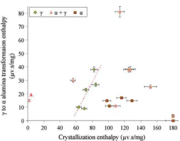
Figure9 is a summary of the relation between trans-formation enthalpy for c- to a-alumina and the crystalli-zation enthalpy that represents the amorphous content in the coatings. In these coatings, the alumina in as-deposited condition has either c or a structure, or mixture of both phases. This figure shows that when the as-sprayed struc-ture contains mainly c-alumina, there is a steep linear relationship between the crystallization enthalpy (the amorphous content) and the c to a transformation enthalpy (that represents the amount of c alumina after crystallization process). This clearly indicates that increasing the amorphous content increases the amount of transformable c to a structure.
Conversely, when the as-deposited alumina is of mainly a-structure, even at larger amorphous contents, the transformation enthalpy from c to a is not increasing, but it is normally almost equal to that of the crystalline sam-ples with no amorphous phase (indicated as point A in Fig.9where the crystallization peak area is almost zero). This shows that in such coatings the alumina in the amorphous phase has lower tendency for crystallization into c; but it prefers to nucleate on the pre-existing a-phase, so that the amount of c-phase and consequently the c to a transformation enthalpy does not change with
the amorphous content. In these coatings the tendency for crystallization on pre-existing a-structure can sometimes prohibit any transformation into the c-phase as can be seen in the sample assigned by point B in Fig.9. Point B represents a coating with very large crystallization enthalpy (amorphous content) in which the a-phase is the predominant structure for the alumina. In this sample, the c to a transformation enthalpy is zero that means during crystallization of the amorphous phase, no c-alumina could have formed.
These observations suggest that the preferred phase during crystallization of the amorphous phase is depen-dent on the initial crystalline structures that can act as the nucleation sites for the crystallizing phases. Thus, in the coatings with mixed structure a compromise between the amounts of the two structures (a- and c-alumina) in the as-deposited coating is expected to determine the pro-portion of the resulting phases after crystallization process. The stabilized zirconia after crystallization did not go through any further phase transformation. Thus, this sort of evaluation for zirconia component was not possible. However, the XRD pattern of the heat-treated sample, as will be discussed later, shows that the resulting structure after crystallization is not different from the crystalline YSZ initially present in the as-deposited coating.
Another noticeable observation in Fig.9 is that the coatings with mainly a-alumina structure also show a high content of amorphous phase. The reason for this concur-rence must be due to the lower particle velocity that was found here to favor the formation of a-alumina. The lower particle velocity results in longer dwelling time at high temperature that could provide the possibility for better mixing. The amorphous formation in a multicomponent system is influenced by the ratio of dissolution of the components. On the other hand, alumina and YSZ are almost immiscible in solid state and can mix only after melting. As a result, the lower particle velocity that causes
Fig. 9 c- to a-alumina transformation enthalpy vs. crystalliza-tion enthalpy during heating the coatings with the crystalline alumina phase in the form of mainly c, mainly a or mixed structures in as-deposited condition
Peer
longer time at high temperature lead to the ideal condition for melting and mixing of the components simultaneously. This issue will be investigated further in the near future. 3.5 Heat Treatment
Heat-treated samples at 700 °C for 12 h show the same XRD patterns as the initial coating. The pattern also did not show any peak shift or change in grain size. This suggests that for such samples the relaxation phenomenon in the DSC curve of Fig.8 does not involve any crystal-lographic phase transformation or thermal residual stress relief.
It was noticed that for most of the heat-treated coatings even at higher temperatures peak shifting did not happen. This shows the low level of the residual stress in these samples. This stress in the coatings with the microstructure as in Fig.4(a) should have been released by extensive cracking (Ref16). On the other hand, the microstructures such as that in Fig.4(b) with comparatively loose and small splats do not accumulate any considerable residual stresses. Therefore, the SPS coatings of small particles do not involve any large accumulated residual stresses.
Heat treatment at 1000 °C for 1 h was carried out to investigate the crystallization phenomenon noticed in the DSC spectra. The XRD pattern of the heat-treated sample was similar to that in Fig.10(a), consisting of cubic zir-conia and c-alumina. In addition, background humps of some amorphous phases were observed within the two ranges of 2h angles, i.e., 21-40° centered at almost 31° and 42-70° centered at about 58°. Following the heat treatment at 1000 °C for 1 h, the heights of the amorphous humps were largely reduced; meanwhile the coating showed wider peaks that were more obvious in the peaks of c-alumina phase as shown in Fig.10(b). Since the primary structure formed from the amorphous phase in case of alumina (in the absence of pre-existing a) is expected to be c-alumina (Ref 31), wider peaks indicate smaller average grain size as a result of crystallization of
amorphous phase into nanocrystalline structure. The quantitative investigation of the grain size according to the amorphous phase content will follow in the future.
Heat treatment at 1200 °C for 24 h results in appearing the a-alumina at the expense of diminishing the c-alumina peaks. This observation supports the proposed identity for the concerning peak that takes place within the range of 1200-1400 °C in DSC spectrum of Fig.8. In contrast, in the coatings with mainly a-alumina in as-deposited con-dition, this heat treatment did not result in any crystalline changes.
The structures of different samples after 1500 °C heat treatment for 5 h are similar and consist of a-alumina and cubic zirconia. Although, sometimes the tetragonal zirco-nia phase is found in the samples, when pre-existing tetragonal phase was present before heat treatment, cubic zirconia phase was mostly retained and no traces of monoclinic zirconia could be found in any of the heat-treated samples. Conversely, based on the reports in ZrO2-8 wt.% Y2O3 coating, at 1000 °C the depletion of yttrium from zirconia unit cells has already started and at 1400 °C after 24 h about 35% monoclinic zirconia was formed (Ref32). This indicates the considerable stability of this composite compared with conventional YSZ and its ability to prevent the transformation to monoclinic zirco-nia which is a major concern in TBCs performance.
It is also worth noting that coating samples upon heat treatment showed crack development that was more pro-nounced after high temperature heat treatments (1200 and 1500 °C). It can be mainly due to the c- to a-alumina phase transformation that involves about 9% shrinkage in volume (Ref7). Crack formation at low temperature heat treatments (700, 1000 °C) can be related to the substrate/ coating expansion mismatch.
4. Conclusion
In this work, the particle velocity is found as a crucial parameter dictating the crystalline structure of the resulting coatings. Particle velocity can be controlled by plasma parameters such as, plasma gas type and the plasma condition that in turn, determines the plasma power.
Particle temperature, as long as it is high enough for complete melting of the particles, does not play an explicit role in the type of phases. It, however, can affect the phase contents when raised far beyond the melting points of the components. Feed size also can affect the phase contents, so that the larger particles result in formation of more stable phases in the coating. Other feed parameters including feed rate and solid content influence the results through variation of the particle temperature.
The presence of unmolten nanoparticles increases the intricacy of the phase prediction in as-deposited coating.
Thermal evolution of the combined crystalline/amor-phous structure of the composite coating results in crystallization of the amorphous phases as dictated by the
Fig. 10 The effect of heat treatment on, (a) as-sprayed alumina—YSZ coating, (b) heat-treated coating at 1000 °C/1 h, and (c) heat-treated at 1200 °C/24 h
Peer
pre-existing structures in the as-deposited coatings. Thus, the in-flight particle velocity can also play a significant role on the final coating structure after crystallization, as it determines the initial phases in the as-deposited state.
Heat treatment at the alumina transformation tem-perature (1200 °C for 24 h) leads to a coating composed of mainly a-alumina phase in addition to the cubic zirconia. The crystallized structure seems to form smaller nanograins than what could be produced during plasma spray deposition. This observation needs more detailed investigation in a future work.
Acknowledgment
Financial support from the Natural Sciences and Engineering Research Council of Canada (NSERC) is gratefully acknowledged.
References
1. M. Yashima, M. Kakihana, and M. Yoshimura, Metastable-Stable Phase Diagrams in the Zirconia-Containing Systems Utilized in Solid-Oxide Fuel Cell Application, Solid State Ionics, 1996,86-88, p 1131-1149
2. C.G. Levi, Emerging Materials and Processes for Thermal Barrier Systems, Curr. Opin. Solid State Mater. Sci., 2004,8(1), p 77-91 3. M. Andritschky, I. Cunha, and P. Alpuim, Thermal Stability of
Zirconia/Alumina Thin Coatings Produced by Magnetron Sput-tering, Surf. Coat. Technol., 1997,94-95(1-3), p 144-148 4. A.M. Limarga, S. Widjaja, and T.H. Yip, Mechanical Properties
and Oxidation Resistance of Plasma-Sprayed Multilayered Al2O3/ZrO2 Thermal Barrier Coatings, Surf. Coat. Technol.,
2005,197(1), p 93-102
5. P. Ramaswamy, S. Seetharamu, K.B.R. Varma, and K.J. Rao, Al2O3/ZrO2 Composite Coatings for Thermal-Barrier
Applica-tions, Compos. Sci. Technol., 1997,57(1), p 81-89
6. M.A. Golozar, J. Mostaghimi, T.W. Coyle, and R. Soltani, Wear Behavior of Nanostructured and Conventional Y-PSZ Coatings, Materials Degradation: Innovation, Inspection, Control and Rehabilitation, Proceedings of the International Symposium on Materials Degradation: Innovation, Inspection, Control and Rehabilitation, August 21-24, 2005 (Calgary, AB, Canada), 2005, p 273-285
7. R.J. Damani and P. Makroczy, Heat Treatment Induced Phase and Microstructural Development in Bulk Plasma Sprayed Alu-mina, J. Eur. Ceram. Soc., 2000,20(7), p 867-888
8. K.S. Ravichandran, K. An, R.E. Dutton, and S.L. Semiatin, Thermal Conductivity of Plasma-Sprayed Monolithic and Multi-layer Coatings of Alumina and Yttria-Stabilized Zirconia, Am. Ceram. Soc., 1999,82(3), p 673-682
9. E.T. Strangman and D. Raybould, Durable Thermal Barrier Coatings, U.S. Patent 2006/0115660, 2006
10. Z. Chen, R.W. Trice, M. Besser, Xiaoyun Yang, and D. Sordelet, Air-Plasma Spraying Colloidal Solutions of Nanosized Ceramic Powders, J. Mater. Sci., 2004,39(1), p 4171-4178
11. Y. Zeng, C. Ding, and S. Lee, Plasma Sprayed Coatings Using Different Nano-size Alumina Powders, Thermal Spray 2003: Advancing the Science and Applying the Technology, Proceedings of the International Thermal Spray Conference, May 2003 (Orlando, FL, United States), 2003, p 671-674
12. X. Zhao, Y. An, J. Chen, H. Zhou, and B. Yin, Properties of Al2O3-40 Wt.% ZrO2 Composite Coatings from Ultra-Fine
Feedstocks by Atmospheric Plasma Spraying, Wear, 2008, 265(11-12), p 1642-1648
13. S. Dosta, I.G. Cano, J.R. Miguel, and J.M. Guilemany, Produc-tion and CharacterizaProduc-tion of Metastable ZrO2-Al2O3 Coatings
Obtained by APS + Quench, J. Therm. Spray Technol., 2008, 17(3), p 360-364
14. J. Oberste Berghaus, J.-G. Legoux, C. Moreau, F. Tarasi, and T. Chraska, Mechanical and Thermal Transport Properties of Suspension Thermal Sprayed Alumina-Zirconia Composite Coatings, J. Therm. Spray Technol., 2008,17(1), p 91-104 15. A.J. Skoog, A.J. Murphy, and T.J. Tomlinson, Method for
Applying a Plasma Sprayed Coating Using Liquid Injection, U.S. Patent 2006/0222777, 2006
16. A.L. Vasiliev and N.P. Padture, Coatings of Metastable Ceramics Deposited by Solution-Precursor Plasma Spray: II. Ternary ZrO2-Y2O3-Al2O3System, Acta Mater., 2006,54(18), p 4921-4928
17. A.L. Vasiliev, N.P. Padture, and X. Ma, Coatings of Metastable Ceramics Deposited by Solution-Precursor Plasma Spray: I. Binary ZrO2-Al2O3System, Acta Mater., 2006,54(18), p
4913-4920
18. T. Chraska, K. Neufussa, J. Dubsky, P. Ctibor, and P. Rohan, Fabrication of Bulk Nanocrystalline Alumina-Zirconia Materials, Ceram. Int., 2008,34(5), p 1229-1236
19. P. Fauchais, V. Rat, C. Delbos, J.F. Coudert, T. Chartier, and L. Bianchi, Understanding of Suspension DC Plasma Spraying of Finely Structured Coatings for SOFC, IEEE Trans. Plasma Sci., 2005,33(2 Pt 3), p 920-930
20. P. Fauchais, R. Etchart-Salas, V. Rat, J.F. Coudert, N. Caron, and K. Wittmann-Teneze, Parameters Controlling Liquid Plasma Spraying: Solution, Sols, or Suspensions, J. Therm. Spray Tech-nol., 2008,17(1), p 31-57
21. C. Delbos, J. Fazilleau, V. Rat, J.F. Coudert, P. Fauchais, and B. Pateyron, Phenomena Involved in Suspension Plasma Spraying. Part 2: Zirconia Particle Treatment and Coating Formation. Plas-ma Chem. PlasPlas-ma Process.,26, 2006, p 393-414
22. F. Tarasi, M. Medraj, A. Dolatabadi, J. Oberste-Berghaus, and C. Moreau, Effective Parameters in Axial Injection Suspension Plasma Spray Process of Alumina-Zirconia Ceramics, J. Therm. Spray Technol., 2008,17(5-6), p 685-691
23. W. Kraus and G. Nolze, PowderCell, Version 2.4, Programm zur Manipulation von Kristallstrukturen und Berechnung der Ront-genpulverdiffraktogramme, Bundesanstalt fu¨r Materialforschung und-pru¨fung, D-12205, Berlin
24. H. Zhang, X.Y. Wang, L.L. Zheng, and S. Sampath, Numerical Simulation of Nucleation, Solidification, and Microstructure Formation in Thermal Spraying, Int. J. Heat Mass Trans., 2004, 47, p 2191-2203
25. A. Haddadi, F. Nardou, P. Fauchais, A. Grinaud, and A.C. Leger, Influence of Substrate and Coating Temperature on Columnar Growth within Plasma Sprayed Zirconia and Alumina Coatings, United Forum for Scientific and Technological Advances, C.C. Berndt, Ed., ASM International, 1997, p 671-680
26. P. Fauchais, M. Vardelle, A. Vardelle, L. Bianchi, and A.C. Leger, Parameters Controlling the Generation and Properties of Plasma Spray Zirconia Coatings, Plasma. Chem. Plasma Process., 1996,16(1), p 99S-125S
27. A. Vardelle, C. Robert, G.X. Wang, and S. Sampath, Analysis of Nucleation, Phase Selection and Rapid Solidification of an Alu-mina Splat, Thermal Spray: A United Forum for Science and Technological Advances, C.C. Berndt, Ed., ASM International, 1997, p 635-643
28. T. Chraska and H.K. Alexander, Transmission Electron Micros-copy Study of Rapid Solidification of Plasma Sprayed Zirconia-Part II. Interfaces and Subsequent Splat Solidification, Thin Solid Films, 2001,397, p 40-48
29. J.W. Christian, The Theory of Transformations in Metals and Alloys, Elsevier Science Ltd./Pergamon, Oxford, 2002
30. H.-J. Kim and Y.J. Kim, Amorphous Phase Formation of the Pseudo-Binary Al2O3-ZrO2Alloy during Plasma Spray
Process-ing, J. Mater. Sci., 1999,34(1), p 29-33
31. X.-L. Wu, Q. Ren, and X.-M. He, Preparation of Nanoscale High-Purity a-Alumina Powders, Key Eng. Mater., 2007,336-338, p 2051-2053
32. J. Ilavsky, J. Wallace, and J.K. Stalick, Thermal Spray Yittria-Stabilized Zirconia Phase Changes during Annealing, J. Therm. Spray Technol., 2001,10(3), p 497-501