Publisher’s version / Version de l'éditeur:
Construction Technology Update, 2011-03-01
READ THESE TERMS AND CONDITIONS CAREFULLY BEFORE USING THIS WEBSITE.
https://nrc-publications.canada.ca/eng/copyright
Vous avez des questions? Nous pouvons vous aider. Pour communiquer directement avec un auteur, consultez la
première page de la revue dans laquelle son article a été publié afin de trouver ses coordonnées. Si vous n’arrivez pas à les repérer, communiquez avec nous à [email protected].
Questions? Contact the NRC Publications Archive team at
[email protected]. If you wish to email the authors directly, please see the first page of the publication for their contact information.
NRC Publications Archive
Archives des publications du CNRC
Access and use of this website and the material on it are subject to the Terms and Conditions set forth at
Advances in fire suppression systems
Kim, A. K.
https://publications-cnrc.canada.ca/fra/droits
L’accès à ce site Web et l’utilisation de son contenu sont assujettis aux conditions présentées dans le site LISEZ CES CONDITIONS ATTENTIVEMENT AVANT D’UTILISER CE SITE WEB.
NRC Publications Record / Notice d'Archives des publications de CNRC:
https://nrc-publications.canada.ca/eng/view/object/?id=e9f1930d-f459-4af4-b841-7cd5de8a014c https://publications-cnrc.canada.ca/fra/voir/objet/?id=e9f1930d-f459-4af4-b841-7cd5de8a014cSuppressing fire by throwing water onto it has been used since ancient times. To pro-vide an automatic spray of water to control a fire, sprinkler systems were developed in the late 19th century. Since then, automatic sprinklers have become the most common fixed fire suppression system for providing fire safety in buildings.
Sprinklers control fire development by wetting and cooling the fuel surface. They are effective for fires involving solid materi-als (referred to as solid fuels) but are not effective for flammable liquids (called liquid fuels) such as gasoline, diesel and jet fuels. The old adage “oil and water do not mix” must be kept in mind. Fire sup-pression systems for liquid fuels typically use foam or dry chemicals, which cover the
fuel surface, hence limiting thermal feed-back to the liquid fuel surface and fuel vapourization.
Fires in electrical and electronic facilities call for special solutions for suppression. Carbon dioxide (CO2) systems were used early on. They deliver large amounts of CO2to the fire area to reduce the oxygen concentration to below the level required for combustion. For total flooding systems, in which pressurized cylinders are con-nected to a fixed piping and nozzle system to discharge the gas into an enclosed space, the oxygen concentration can be reduced to below the level required by occupants. As a result, CO2systems are typically limited to unoccupied spaces.
In the 1940s, there was a major effort to come up with a more effective fire suppres-sion agent than the ones being used at that time. This led to the development of halon chemicals, including Halon 1301, which was typically used for total flooding appli-cations. Halons are excellent fire suppres-sants, but they contribute significantly to stratospheric ozone depletion. As a result, fire protection halons were phased out in developed countries around 1990 when an international consensus (the Montreal Protocol) was reached to regulate the use of ozone-depleting substances.
By Andrew Kim
Fire suppression systems for the protection of buildings have evolved in
response to new requirements, environmental pressures and advances in
technology. This Update provides an overview of four recently developed
systems, reviews research on the performance of each, and provides
guidance on system selection, design and use.
Advances in Fire
Suppression Systems
Construction Technology Update
No. 75
There are two basic methods for applying an extinguishing agent: total flooding and local application. Total flooding means applying an extinguishing agent to a three-dimensional enclosed space in order to achieve a concentration of the agent adequate to extinguish the fire. These types of systems may be operated automatically or manually. Local
applica-tion means applying an extinguishing agent directly onto a
fire (usually a two-dimensional area), or into the three-dimensional region immediately surrounding the substance or object on fire. The main difference between local appli-cation and total flooding design is the absence of physical barriers enclosing the fire space.
The phase-out led to extensive research to find halon substitutes that would work well for various applications without harm-ing the environment and human health. Several new fire suppression systems have been developed and some old approaches have gained renewed interest. This Update reviews four such technologies: inert and halocarbon gaseous agents, water mist sys-tems, compressed-air-foam syssys-tems, and solid gas generators. A subsequent Update will focus solely on compressed-air foam technology, drawing on extensive research carried out by the NRC Institute for Research in Construction (NRC-IRC).
Gaseous Systems
Two types of gaseous agents are available for use in total flood-ing systems: halocarbon agents and inert gases. A general requirement for such systems is that the enclosure must be capable of holding the gas and be able to withstand the high pressures produced during discharge.
To address limitations and proper use of systems involving gaseous agents, the National Fire Protection Association published NFPA 2001[1] “Standard on Clean Agent Fire Extinguishing Systems.” NFPA 2001 is not a design handbook but rather a guide for those dealing with clean agent extin-guishing systems, to help ensure that such equipment will function as intended. The standard contains information on the use and limitations of clean agents, such as the physical properties of halocarbon and inert agents, maximum concentrations allowed, and toxicity of the agents. It also addresses system components and hardware, system design, inspection, maintenance, testing and training.
Halocarbon Agents
Halocarbon agents are chemicals similar to halon except that their molecular structure has been modified to reduce the number of, or to eliminate completely, the chlorine and bromine atoms, which are responsible for ozone depletion. These agents extinguish fires primarily by cooling.
Acceptance of a halocarbon agent by regulatory authorities hinges on the agent’s toxicity. Two toxicological aspects must be considered. One is the toxicity of the agent itself, and the other is the toxicity of com-bustion by-products of the agent produced under fire conditions.
Results from both small-scale and full-scale tests have shown that the halocarbon replacement systems extinguish fires well, though not as effectively as halons. To pro-vide the same level of fire protection as halons, larger amounts of halocarbon agents are needed. This means larger and heavier cylinders are required, which may create weight and space problems (Figure 1).
The test results also show that halocarbon agents produce five to ten times more toxic gases than Halon 1301 during fire suppres-sion. These gases include hydrogen fluoride (HF) and carbonyl difluoride (COF2), with levels produced in test fires significantly exceeding all human exposure limits. The levels of HF and COF2likely to be produced in actual applications will depend on many factors such as agent type and concentration, fire type and size, and discharge and extin-guishment times. Halocarbon agents also produce carbon monoxide (CO) during fire extinguishment, which could be another safety issue, depending on the concentrations and the occupancy of the space.
Some halocarbon agents have a long Atmospheric Life Time (ALT) and could contribute to global warming. This may become a determining factor in selecting suitable suppression agents in the future. Inert Gas Agents
Inert gas agents are applied as total flooding agents. They extinguish fire by displacing the oxygen in the enclosed space and eventually reducing its concentration below the level required for combustion. Inert gases, such as nitrogen, argon and helium, are clean and naturally occurring, have zero ozone depletion potential and no global warming potential. They are not subject to thermal decomposition when used in extinguishing fires, and hence form no combustion by-products.
One of the disadvantages of using inert gas systems is that a large volume of agent is required to extinguish a fire. As well, inert gases cannot be liquefied and must be stored in cylinders as high pressure gases,
2
Figure 1.Weight and space issues can arise with the use of cylinders
which has implications for space and weight. Inert gases also require a discharge system sufficiently robust to withstand the high pressures involved. The rapid displacement of oxygen, high noise levels and rapid cooling are also a concern if the agent is to be discharged into an occupied space.
Water Mist
The term "water mist" refers to fine water sprays in which 99% of the volume of the spray is in droplets smaller than 1000 microns in diameter.
For water mist systems, a standard NFPA 750[2], “Standard on Water Mist Fire Protection Systems,” was developed by NFPA. The standard specifies minimum requirements for the design, installation, maintenance, and testing of water mist fire protection systems. It does not provide definitive fire performance criteria nor does it offer guidance on how to design a system to suppress a fire.
Fire suppression by water mist is mainly by physical mechanisms. No significant chemical effects are involved. While early studies identified flame cooling and oxygen displacement as the dominant mechanisms, recent investigations suggest that there are additional ones. The main one is radiation attenuation, which can stop the fire from spreading to an un-ignited fuel surface and reduces the vapourization at the fuel sur-face. Tests conducted at NRC-IRC showed that the radiant heat transfer to the walls of the test compartment was reduced by more than 70%. Other secondary extinguishing mechanisms include dilution of flammable vapours released by the burning objects, and wetting and cooling of these objects by direct impingement.
Water mist does not behave like a “true” gaseous agent. The NRC-IRC compartment tests showed that its effectiveness in fire suppression is substantially affected by the fire size, the degree of obstruction, ceiling height, and the ventilation conditions. Water mist characteristics, such as variety of drop sizes and spray momentum, have a direct influence on effectiveness. To effec-tively suppress a fire, a water mist system must generate and deliver optimum-sized droplets with an adequate concentration. The selection of the optimum size of droplets for the design of the system is dependent
on the potential size of the fire, properties of the combustibles, and the degree of obstruction and ventilation in the compart-ment. There is no one drop size distribution to fit all fire scenarios.
There are several water mist systems available commercially. Some employ high or intermediate pressures of water through small orifices in a nozzle to produce the mist, while others use twin fluid nozzles (water and air).
Water mist systems have demonstrated a number of advantages, such as good fire suppression capability, no environmental impact and no toxicity. As a result, they have been considered for numerous appli-cations. One potential application is ship-board machinery spaces. Water mist systems are able to extinguish a wide variety of fires when natural ventilation, such as open doors and hatches are allowed, whereas gaseous agents were not effective under such conditions. Water mist systems also rapidly reduced the compartment tempera-ture and significantly improved visibility. These advantages allow accessibility to the compartment during fire suppression.
Another application where water mist has potential as an effective halon alterna-tive is the protection of electronic equip-ment. The telecommunications industry and utilities have generally been reluctant to use water as a fire suppressant because of concerns about damage to electrical and electronic equipment. A preliminary study by NRC-IRC on the feasibility of using a water mist system to suppress in-cabinet electronic fires showed that the system was effective without causing short circuits or damage to the equipment.
Recent NRC-IRC research[3] in a test compartment has shown that the fire sup-pression performance of water mist can be further improved by using a cycling dis-charge. This feature involves a continuous alternation of an ON and OFF cycle of the mist discharge. When a fire was minor, the extinguishment was easy and the contribu-tion made by the cycling discharge was small. For more challenging fire scenarios, such as ventilated conditions, the cycling discharge significantly reduced extinguish-ment times and water requireextinguish-ments. More water vapour and combustion products were produced, which increased the rate of
oxygen depletion. In addition, the recurrent dynamic mixing created by a cycling dis-charge effectively dilutes the oxygen and fuel vapour available for the fire.
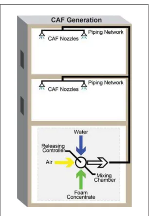
Compressed-Air Foam
For decades, foam systems have been used to provide fire protection in the chemical and petroleum industries and in military installations. The overall effectiveness of current fixed-pipe foam systems, which incorporate aspirating-type nozzles and blower-type foam generators, is limited since they are unable to provide foams with high injection velocities. As well, the foam produced using traditional systems is not as stable and consistent, and expansion ratios are not as high as desired for some applica-tions, because the air to generate foam at the nozzle, which comes from the fire envi-ronment, may be contaminated. However, if compressed air is used for foam generation, the foam possesses superior quality and substantial injection velocity, as well as requiring a much smaller quantity of water and foam concentrates.
Compressed-air foam (CAF) is generated by injecting air under pressure into a foam solution stream (Figure 2). The process of moving the solution and air mixture through the hose or piping, if done correctly, forms a foam. The energy for the CAF comes
from the combined momentum of the foam solution and air. One significant advantage of such systems is the increased momentum of the foam, enabling it to penetrate flames and reach the fuel surface. Another advan-tage of CAF is that it possesses greater sta-bility with respect to drainage (foam does not collapse easily) than air-aspirated foams, since it is characterized by a narrow distribution of bubble sizes.
Early attempts to adapt CAF to fixed installations failed, owing to two fundamen-tal technical difficulties: first, traditional sprinkler-type nozzles cannot distribute compressed-air foam without collapsing it, and second, the foam itself degenerates in fixed piping. Recently, NRC-IRC overcame these difficulties and developed a means of producing CAF using Class A and Class B foam concentrates in a fixed-pipe system, using a new and innovative foam distribution nozzle. Foam break-up, which prevented the development of this technology in the past, was avoided by careful engineering design of the nozzle and the piping system.
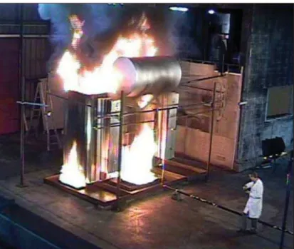
NRC-IRC conducted full-scale fire tests to evaluate the performance of a prototype CAF system (Figure 3). The tests demon-strated the superior performance of the system in extinguishing both liquid fuel and
4
Figure 3.CAF extinguishment versus water (deluge) extinguishment
wood crib fires with a small amount of water. Also, CAF requires a smaller amount of foam concentrate to provide effective suppression, compared to systems based on air-aspirated nozzles. In the NRC-IRC tests, less than one half of the normally recom-mended (for air-aspirated systems) Class A and Class B foam solutions were used with-out compromising the extinguishment effi-ciency of compressed-air foams [4].
Recently, NRC-IRC developed a prototype CAF system for practical application in providing fire protection to very large structures, such as aircraft hangars and power transformers. Full-scale experiments carried out with the prototype proved the superior performance of CAF in extinguishing simulated fuel spill and transformer fires (Figure 4).
Currently pre-engineered CAF systems are being developed for a variety of com-mercial applications.
Gas Generators
Based on automotive airbag technology, gas generators have been developed for fire suppression applications. Gas generators can produce a large quantity of gases (mainly N2, CO2and water vapour) by combustion of solid propellants. Solid propellants consist of oxidizers and fuel ingredients, and are able to burn without ambient air. Gas generators can be very compact and can provide very fast discharge (in a few
milliseconds). Currently, there are two types of gas generators available: conven-tional and hybrid.
Conventional gas generators contain a propellant and an electrical initiator. When a signal is received from a detector/controller, the electrical initiator ignites a charge to start a combustion process in the propellant. Rapid combustion of the solid propellant generates large amounts of N2, CO2and water vapour, which rapidly increases the internal pressure. A hermetic seal is ruptured and the gas products are dis-charged within milliseconds into the pro-tected space. Suppression is by oxygen displacement and gas discharge dynamics (blowing effect).
A hybrid gas generator consists of an electrical initiator, a solid propellant chamber and a suppression agent chamber (Figure 5). The heat and pressure generated by the combustion of the propellant are used to heat and expel the liquefied suppressant.
Gas generators are limited for use in unoccupied spaces only, because of their high temperature and high momentum discharge.
Figure 5.Hybrid gas generator
Figure 4.Extinguishment of a transformer fire using CAF
Initiator Solid propellant Liquid suppression agent
Guidance for Users
Each of the fire suppression systems dis-cussed here work well and have certain advantages and disadvantages depending on the specific application, summarized as follows.
For gaseous systems, the fire hazard must be in an enclosed space. If the room has many openings, a gaseous system may not be able to maintain its design concentration, and may fail to extinguish the fire. Also, because halocarbon gaseous agents produce toxic gases, steps must be taken to minimize gas production and exposure to it.
Water mist systems work well with a large fire in a reasonably enclosed space, such as a room with doors and windows open. If the fire is hidden or shielded from the water mist spray, the fire may not be extin-guished. Fire suppression effectiveness depends on many factors, such as room geometry, location of the fire with respect to the nozzle, and obstruction. A water mist system is used to replace a sprinkler system where the need for reducing water damage is great, such as in museums and art galleries.
A CAF system works best in extinguishing liquid fuel fires. It can suppress fires in an open area and does not require an enclosure. It also requires far less water than conven-tional water-based systems. However, a CAF system will have difficulty extinguishing 3-D fires, such as a spray fire.
Gas generators work well in relatively small and airtight compartments. They are typically used where installation of piping for conventional fire suppression systems is difficult, or where there is a need for quick fire extinguishment. They can only be used in a location where no person is present, such as an engine compartment or storage space.
Conclusions
Since the phase-out of halon, a major thrust to develop new advanced fire suppression systems has produced several effective options. These include halocarbon and inert gas systems, water mist, compressed-air-foam, and gas generators.
All of these systems extinguish fires at their design conditions. However, no one system can be chosen as the best system for all applications. Some perform better than others in a specific application. All have limitations and raise concerns that have to be dealt with. It is important that all the advantages and disadvantages of each fire suppression system be considered in rela-tion to the specific requirements to select the best system for the application.
References
[1] NFPA 2001 (2000), “Standard on Clean Agent Fire Extinguishing Systems,” National Fire Protection Association, Quincy, MA, U.S.A., 2000 Edition, pp. 1-104.
[2] NFPA 750 (2010), “Standard on Water Mist Fire Protection Systems,” National Fire Protection Association, Quincy, MA, U.S.A., 2010 Edition, pp. 1-69. [3] Kim, A.K., Liu, Z. and Su, J.Z. (1999),
“Water Mist Fire Suppression using Cycling Discharges,” Proceedings of
Interflam ’99, Edinburgh, UK, p. 1349.
[4] Kim, A.K. and Dlugogorski, B.Z. (1997), “Multipurpose Overhead Compressed Air Foam System and its Fire Suppression Performance,” Journal of Fire Protection
Engineering, Vol. 8, No. 3, p. 133.
Dr. A.K. Kim is a senior research officer in the
Fire Research program of the National Research Council Institute for Research in Construction.
“Construction Technology Updates” is a series of technical articles containing practical information distilled from recent construction research.
For more information, contact Institute for Research in Construction, National Research Council of Canada, Ottawa K1A 0R6.
Telephone: (613) 993-2607; Facsimile: (613) 952-7673; Internet: http://www.nrc-cnrc.gc.ca/irc
© 2011
National Research Council of Canada March 2011