Design of a Guideway for a Model MAGLEV
Vehicle
by
KeIlneth MN.
Peters
Submitted to the Department of Mechanical Engineering
in partial fulfillment of the requirements for the degree of
Bachelor of Science in Mechanical Engineering
at the
-MASSACHUSETTS INSTITUTE OF TECHNOLOGY
Feb 1993
i) Massachusetts Institute of Technology 1993. All rights reserved.
Author ' ...
Department of Mechanical Engineering
Jan 15, 1993
Certified
by...
Accepted
...
Richard D. Thornton
Richard D. Thornton
Professor of Electrical Engineering
Thesis Supervisor
by
..
I.-.
4 .
.
'-.
.-...-...
I/.l/'
~Peter
Griffith
Chairman, Departmental Committee on Undergraduate Studies
Design of a Guideway for a Model MAGLEV Vehicle
by
Kenneth M. Peters
Submitted to the Department of Mechanical Engineering
on Jan 15, 1993, in partial fulfillment of the requirements for the degree of
Bachelor of Science in Mechanical Engineering
Abstract
This thesis presents the design of a 40 meter oval guideway for a small scale, wheeled, permanent magnet, MAGLEV vehicle. The guideway has two six phase linear motors and is designed to be powered in segments. The proposed guideway is an extremely thin boxbeam design that is focused around manufacturability. Several winding schemes for the motor were discussed and equations for properly banking the cir-cular curves and calculating their spiral lead-ins were solved. Specifically addressed are designs for supporting clamps, linear motor guides, and electrical interconnectors. Blueprints for all parts are included.
Thesis Supervisor: Richard D. Thornton Title: Professor of Electrical Engineering
Table of Contents
1 Introduction 7
1.1 Introduction 7
1.2 Overview and Advantages of the New Guideway 10
2 General Design For the Track 10
2.1 Introduction to Design Constraints 10
2.2 The Guideway in Conjunction with the Vehicle 10
2.3 Influences of the Linear Motor on the Guideway 12 2.4 Influences of Manufacturing Constraints on the Guideway 13
2.5 Other Constraints 14
2.6 The General Guideway Design in Response to These Criteria 14
3 Design of Supports and Connections 19
3.1 Overview 19
3.2 The Support Clamps 19
3.3 The Linear Motor and Motor Connections 23
3.4 The Electrical Connectors 28
3.5 The Mechanical Clamp 29
4 The Guideway Web 34
4.1 Number and Length of Track Segments 34
4.2 The Straight Sections 35
4.3 The Curved Sections 36
4.3.1 Banking 36
4.3.2 Fabrication Problems with Banking 36
4.3.3 Forming the Cone 39
4.3.4 Finding the Hole Locations 41
4.3.5 Final Layout 47
4.4 The Spiral Transition Curves 47
4.4.1 Why use spirals 47
4.4.2 Acceleration in the Moving Frame 48 4.4.3 Equations of Motion for the Circle 49 4.4.4 Equations of Motion for the Spiral 51 4.4.5 Length of the Transition Spiral 53 4.4.6 Construction of the Spiral 55
5 Conclusions and Recommendations 59
5.1 Possible Problems 59
5.2 Production Recommendations 60
Appendices 62
List of Figures
1-1 Track Layout 9
2-1 The Overall Guideway 15
3-1 The Support Clamp 21
3-2 Dimensions and Phases of the Linear Motor 24 3-3 Winding Pattern for a Single Phase 25
3-4 Magnified Litz Wire Bundle 26
3-5 Parallel and Series Connections 27 3-6 Series and Parallel connections for One and Two Tracks 27
3-7 The Electrical End Connector 30
3-8 The Wire Guiding Clamp 31
4-1 Force Diagram of a Banked Turn 37
4-2 Banked and Curved Guideway 39
4-3 Cross Section of Banked Turn 40
4-4 The Flat Transformation of the Cone's Surface 41
4-5 Production Blank 42
4-6 Transformation of Axes for Conical Section 43 4-7 Finding the Origin of the Blank 45
4-8 Rotation of Coordinate Axes 46
4-9 Path of a Particle Through Space 50 4-10 Plots of Normal Acceleration Versus t 52
4-11 Insertion of Proper Spiral 54
Chapter
1
Introduction
1.1 Introduction
The purpose of this thesis is to design a test track for a small scale MAGLEV vehicle. Since 1991 MAGLEV research and development has been going on at Laboratory for Electronic and Electromagnetic Systems at MIT. This research has been in the form of general research and in the creation of small scale working models for experimentation and testing. This proposed new track and vehicle form the next logical progression in the series of prototypes for the MAGLEV project.
1.2 Overview and Advantages of the New Guideway
One of the advantages of this proposed guideway is its size. Because it is much larger than the guideways used in previous models this new track will allow tests at greater speeds for longer duration due to its greater length of travel. The new track will be powerful enough to drive a 1 meter bogey at speeds of 2 to 3m/s for indefinite periods of time.
From an electrical standpoint, propulsion will be supplied by two linear motors instead of the single winding used in the previous models. The motors will be wound in a 6 phase configuration rather than a 3 phase configuration and will be powered by several sets of power controllers instead of a single unit. These improvements over the previous track enable vastly different and vastly more frequent experiments to be run. Also, since this guideway more closely approximates the guideway proposed for the real system, the applicability of the experiments is increased as well.
Because the new track calls for two linear motors driven by multiple power inverters in several zones, experiments involving switching and
communication between adjacent zones, experiments in linear motor control, and propulsive tests such as the coordination of the linear motors may be attempted. Experiments such as trying different winding configurations and trying power supplies with different voltage and current capabilities may also be instigated. Since these experiments directly address problems that must be dealt with in the full size vehicle their results should provide a useful set of data and conclusions for building the full scale train. With the older track that was limited to a single linear motor driven by a single power inverter in one zone these experiments could not be carried out.
Geometrically this new guideway offers distinct advantages over the previous models as well. The test track is to be an oval course roughly 40 meters long with two 4 meter straightaways and two 4 meter radius turns.
The oval nature of the track in a sense provides an "infinite distance" over which the vehicle can be accelerated. This layout enables tests at various cruising speeds as well as tests of controlled of acceleration and breaking. The curves themselves form a useful forum for experimentation as viable solutions
to many of the problems experienced by the full scale train as it approaches and traverses curves do not exist. Special "curve traveling" designs of bogies can be refined on this track and physical anomalies such as phase matching in the linear motors along the curves can be
4 meters I I- -I
Figure 1-1 Track Layout
investigated.
From these arguments it is apparent that this new guideway offers
distinct advantages over the previous models. It more closely resembles the full size system and enables experiments to be performed that could not be carried out with the other test track. Now that we have justified the reasons for
producing the new guideway, we can move on to the criteria for its design and the solutions adopted to meet these constraints.
Chapter 2
General Design For the Track
2.1 Introduction to Design Constraints
Because the guideway and bogey constitute a rather complicated
electromechanical system, various constraints are placed upon the guideway's design owing to the inherent natures of the electromagnetics and the
mechanics involved. The primary influences on the guideway design are contributed by the vehicle the track must accommodate, the track's linear motor and its power source, and the production limitations placed by manufacturing processes on the track. These influences and their tradeoffs are discussed in the separate sections below.
2.2 The Guideway in Conjunction with the Vehicle
Because the train draws its power and its guidance from the track on which it travels, it is reasonable to assume that the design of the guideway should be directly coupled to that of the vehicle. The following are the constraints that the vehicle places on this guideway.
1) Because scaling to a small size is unfavorable to magnetic levitation, the train is designed to have permanent magnets and will be too heavy to
levitate. Without levitation there is no magnetic force counteracting gravity so the train must be physically supported by the guideway. Wheels or bearings of some sort must be used to support the weight of the train and constrain its
motion to the track. Since we do not want power to be dissipated through rubbing between the train and the track these guides or bearings should be as frictionless as possible.
2) The weight of the vehicle requires the guideway to be strong and rigid. The track must be able to support the forces on the vehicle in the straight
sections and in the turns without flexing or yielding. It should always keep the train, the motor windings, and the magnets on the vehicle in proper alignment.
3) The magnets of the train should be mounted as closely as possible to the motor windings to draw the maximum propulsive force from the motor. Since the field lines from permanent magnets do not travel in straight lines but instead radiate outward in curves, if the magnets are placed closer to the windings a greater number of field lines will pass through each loop of wire in the motor. The magnetic flux that is linked by the winding will increase and
hence by Lorentz's force law the accelerations on the vehicle increase as well. This configuration utilizes the available magnetic field more efficiently.
4) The train should be able to be placed on and removed from the track easily. This requirement is necessary to enact repairs, to try different
configurations of sensors, and to use different vehicle designs. Since the vehicle itself is a prototype many changes to its design inevitably will be made. The track should facilitate removal and replacement of the vehicle to make these changes.
2.3 Influences of the Linear Motor on the Guideway
The second primary source of constraints on the guideway is the linear induction motor that provides the propulsive force to the train. This motor runs the entire length of the track and imposes certain geometric, material, and power electronic conditions on the guideway. These conditions are described below.
1) The guideway in the region of the windings should be made of
nonmagnetic and nonconducting materials. Since the magnets of the vehicle pass over the windings and achieve their propulsive forces from their magnetic fields, materials with high magnetic permeability should not be used in the track. These materials would alter the field lines of the windings and detract from the
efficiency of the motor. Non-conductive materials should be used owing to Faraday's law. Since the motor windings are driven periodically a changing magnetic field is seen by the track. If conducting materials are used here eddy currents will be induced. Similar losses are induced from the magnets
mounted on the vehicle. As the train moves along the track its magnets create a changing magnetic flux (dB/dt). Once again, currents will be induced and i2R power losses will result.
2) The track must be made in sections. Since one of the power
electronics problems this model is designed to address is the switching when running the train, multiple power inverters in several different configurations
may be used to drive the windings of the motor. Building the windings in
sections allows these converters to be inserted and removed easily at different places in the track.
3) The track should be built with two different linear motors. Since the final vehicle will be driven by different linear motors on either side of the track, the model should also have two motors to simulate and experiment with these conditions.
2.4 Influences of Manufacturing Constraints the Guideway
In addition to accommodating for the engineering constraints of the motor and the vehicle the guideway must also be designed for
manufacturability. 40 meters of test track is a long guideway to fabricate and the track should be designed such that construction is simple and fabrication time is reduced. The following manufacturing constraints are influences to be
considered due to limitations of manufacturing processes.
1) Parts should be as few in number and as simple as possible to manufacture. This requirement cuts down on the overall production time in the obvious way that fewer things must be produced.
2) Parts should be standardized. This allows templates and jigs to be used in production so parts can be built several at a time instead of having to be custom built individually.
3) Tolerances should be increased where at all possible. By increasing tolerances we limit the accuracy to which the parts must be manufactured. If extreme accuracy is not a requirement, alternate types of fabrication processes
(such as sawing or shearing instead of milling) can be used. These processes are usually much faster and fabrication time can be cut down substantially.
4) Parts should be made flat and with as few intricate patterns as
required to manufacture a part and limits the part's accuracy since frequent repositioning is required to create the proper piece. Complex curves should be avoided if at all possible since they are very difficult to machine on standard shop equipment and oddly shaped parts or custom fasteners should be avoided where standard bough items could be substituted.
6) Parts should be made of sizes that are easily handled by standard shop equipment. Since the raw materials must originally be worked upon by particular machines for fabrication, it only makes sense that the sizes of these parts correspond to the abilities of the machines used for manufacture.
2.5 Other Constraints
The final constraint is portability and ease of assembly and disassembly. This model is designed not only for experimentation but also as for display purposes. Thus it is possible that the track will need to be moved to other sites and set up for demonstrations. This set up and take down should be simple enough so the track can be moved easily and assembled in a short amount of time. To accommodate this goal the track must be able to be disassembled into
small pieces and the number of fasteners and interconnections required must be limited. Continuity of parts should be maintained so only a few tools need to be used to assemble and disassemble the entire track.
2.6 The General Guideway Design in Response to These Criteria
The proposed guideway design is drawn in relation to the vehicle and
explained in Figure 2-1. The guideway is made up of 42 inch sections of
fiberglass webbing that may be assembled to form the entire track. These pieces come 3 types: straight sections for the straightaways, circular arcs for the
'0
.m CDC
0 .1 -U U) * 4i z *i Cd, I-0 c 3 IE (U I-03 @1 U) U) C U) C 0 Ez
a, 11 Lt, N E cu 4-10 0k. C w 0 .. H Uu S U o 0-:> cp U r> a) V- F -- o0 * E 0 3:E -W &, M (n 4' un co rN CG CD NC m UI
o-' C3-0 Cv)f
'A=~
C, 0
t
S
L
B r O~'
u0
U- r- N C V) U- r- r-U-I
[ L_C-0
a a)I-N
a, U. _a -I I U m U U w1~m -81188888~~ ' IU
1 U J-| . S--3 D T-·l ·- I - · · r-·l I I---- T7 I L-I I II Li n m ., msla _19r -s I e I I_ mcurves, and spiral transitions to be used at the juncture between the straight sections and the circular arcs. The spiral transitions smooth the jerk in acceleration as the vehicle enters or exits the curve and the curved sections are banked to compensate for the centripital force placed on the vehicle in its
turn.
The linear motor windings fit on each side of the web into a slot made by two deloren strips called the top rail (number 4 on Figure 2-1) and the guidance
channel(number 9 on Figure 2-1). Deloren is both nonconductive and
nonmagnetic, and it is both hard enough to hold the windings in place yet flexible enough to be bent along the curved pieces of track. It has the nice properties of being extremely easy to machine and being hard enough to hold screw threads but not abrasive enough to rub the insulation off of the winding wires. Deloren also provides an excellent bearing surface for the wheels that
are mounted on the bogey.
Both the top rails and the guidance channels on either side of the track are fixed rigidly in place by screws. Taking the top rail as an example, screws enter through countersunk holes in the right top rail, pass through clearance holes in the fiberglass web, and then thread into holes tapped into the top rail on the left side. This fastening method decreases the required number of parts and allows the magnets of the vehicles to pass more closely to the motor
windings.
The thin fiberglass beam that governs the overall design of the guideway was selected for manufacturing purposes and in response to a new style of electrical winding patented by New England Electric Wire Company. The
"Compacted Rectangular Litz" wire winding process allows strands of wire to be wound into a weave of overlaying wires who's final shape is a flat beam. (See
section 3.3 on the linear motor) This wire was used because it eliminates the problems of using outside supports to keep the wires in their geometrical alignment. Since winding method preserves the pole pitch between the windings itself, the winding only needs to be inserted into the guide channel and epoxied in place.
The thin guideway solves problems in wire continuity and manufacturing. These advantages are most apparent on the turns. The plan is to build the guideway an flat pieces and then flex these pieces into curves. Since it is extremely difficult to manufacture curves accurately this flexing method
simplifies the production process a great deal. A thin guideway must be used to achieve this effect as a thick beam would not be bendable. As for wire continuity, since the outer circumference of a bent beam with some finite thickness is necessarily larger than the circumference of the inner surface, a thick beam results in different lengths of linear motors on either side of the
guideway. Hence, it becomes difficult to align the motor phases on both sides of the track with the vehicle magnets. A thin guideway minimizes the difference in
length of the windings on either side and reduces the error in pole pitch between the magnets and windings. A thin guideway also allows the bogey's wheels to rest on one point in the guideway's center instead of points separated by a larger distance. This eliminates the use of differentials in the bogey's wheels as it goes around curves. Fiberglass was chosen for this webbing because it is non magnetic, flexible, yet firm enough to support the weight of the vehicle and to hold screw holes securely.
Finally there are the specialized structures on the guideway: the support clamps, the interconnectors, and the electrical wiring terminals. These parts address more specific design issues, and though an integral part of the
guideway, they did not impose constraints in determining the overall plan for the test track. The design of these specialized parts and a more detailed analysis of the guideway structure are discussed in the following section.
Chapter 3
Design of Supports and Connections
3.1 Overview
Now that the general design and shape of he guideway has been
established, we focus in on the designs of the individual components that make up the test track. In this way, the smaller details of the problems faced by each part can be described and the reasons for selecting each individual part design
can be explained.
3.2 The Support Clamps
The track must be fixed into the ground in some way so it supports the weight of the vehicle and holds the shape of the curves correctly. To do this, a series of supports was devised. As in the previous chapter, a list of design criteria is stated first followed by the design of the supports. In this way, the reasoning that lead to the design can more easily be followed.
1) The supports should be able to accommodate straight pieces as well as curves. This has the most impact at points where the support actually
contacts the track along a curve as it is often difficult to fasten securely to a rounded surface.
2) The supports should be able to accommodate for the vertical position of the straight sections and the banked position of the curves.
3) The supports should be stable enough to withstand the vertical forces of the track and the lateral forces of the fiberglass webbing in the turns. Since the curves of the track are to be produced by bending flat pieces of fiberglass there will undoubtable be residual forces in the curved pieces that will attempt to "unbend" these sections. The supports must provide enough force against the ground to counteract these residual forces and maintain the proper
curvature of the track.
4) The supports should be easy to manufacture. Since approximately 40 meters of test track is to be built, building the supports will be a substantial task. The supports must be extremely simple to manufacture in quantity, preferably with high tolerances and simple manufacturing processes.
5) The supports should be relatively portable. This particular model vehicle is not designed purely for experimentation but also for demonstration purposes. Because of the need for portability, the supports can not be fastened into the ground like stantions. They should be free standing.
The final design for the supports is a clamping system consisting of one universal clamp that can be produced in quantity and can be used to secure the entire track. This clamp is shown in Figure 3-1.
The clamp consists of a steel C-channel which houses a Deloren cylinder suspended by a bolt. This Deloren cylinder can be rotated and set at any angle by securing the tightening nut(Figure 3-1 number 9). This mechanism provides the angular degree of freedom required by the constraints. The clamp
0
-, r_ C ' ) -m+j
ca-E °
2
= aC
3 0
--
O
- 0m 0
4-0 o E 4- CVc
n =" O 6^ 0 Q O 0 aI
0.
(D 4J 4J =Z
0) 0) n _ sm -m a - 40)
4- ,-wn P 1.0
En 0. E O0
CL Un E 0 m c m <, ce .E c m0 0 0 co _ 0)g
G-4
cfl'O . 4 4 U) co0 CD o CA a) U c c 0 c 4, E .c0 E0
re N LI If-a-cl 0. CL be00
E- N C
, rn,
0 o)
/ ,- N M ' ' LI w r i -JEn :3 S-a co CUa
CU E .0
I-cm I.. l w - -_ ._ . _ --- ---MMMmm~· Mhk L---'- --- - ---J Fj
is fastened to the track by screws through the aluminum plate fixed in the Deloren. The design trade off in this part is associated with the width of the aluminum attaching plate(Figure 3-1 number 1). To prevent the guideway from pivoting around the top of the clamp, this distance should be maximized to produce a longer torque arm. However, when a long flat surface is bolted down to the curve it warps it causes a distortion in the guideway. A spacing of 1.2 inches makes a good compromise providing enough support while deflecting the curve only negligible amounts.
The base of the clamp handles the lateral loads imposed by the guideway, and is specifically designed to take advantages of tolerances in
manufacture. A threaded rod that feeds into the clamp base is welded to the C-channel that forms the bracket for the deloren cylinder is. This rod allows the clamp's height to be adjusted and fixed at any position. This vertical degree of freedom allows the clamps to compensate for soft spots or uneven patches since floors will differ if the track is portable. More importantly, the screw design allows for much easier manufacturability. Since the clamps can be adjusted after placement, only very coarse tolerances need to be kept during production. These coarse tolerances result in a shorter manufacturing time by allowing simpler manufacturing processes to be used. The rod and threaded pipe can now be band sawed to uneven lengths instead of milled to tight tolerances. The base of the clamp is a block of lead with a hole drilled in it.
Because of the lead's great weight, the frictional forces along the clamp's bottom surface are adequate to balance the residual flexing forces in the guideway. Also, because of the simplicity of design, more lead c-.n easily be slipped on if deemed necessary and the bottom of the base could be
of the clamp was kept small to give the entire structure more lateral stability by decreasing the overall moment arm.
Each section of track is designed to have two clamps equally spaced along its length. This configuration provides stability and allows for even bending of the circular curves.
In creating the various part designs, after the final designs were
conceived in each case they were honed down to production standards using formulae and theories explained from lectures by L. E. Sachs in his course at
MIT on Design for Manufacturing. These formulas provide guides to reducing the total number of parts for an object and refining the processes for speed of production. They were applied to all parts designed to convert the designs into
more easily manufactured approaches. In the case of the clamp it was found that the total number of parts could be reduced to 10 and certain simpler processes could be used for manufacture. The blueprints for this clamp appear
in Appendix 2.
3.3 The Linear Motor and Motor Connections
An explanation of how the design of the linear motor affects the overall guideway design was presented in section 2.6. While the criteria that determine the specifications of the linear motor are beyond the scope of this thesis, some
understanding of the motor's geometry is necessary to construct the guideway. The intricacy of the motor's geometry is important because one of the design requirements for the track was to build the guideway in sections to allow powering of different lengths of track by more than one power inverter.
reliable connectors are needed to connect the windings of the linear motor from one track section to the next. Furthermore, it is undesirable to allow a gap between the windings as they make this transition. A physical gap causes
a discontinuity in the pole pitch of the motor. The consequence associated with
this discontinuity is the formation of an "electromagnetic pot hole." A short description of the winding is presented here to understand how its geometries dictated the connector design.
The linear motor winding selected is a helical winding consisting of a 24 strand bundle of seven conductor Litz wire pressed into a flat ribbon of cable. The wire is woven upward at a 19.6 degree angle, and then flipped and turned downward so that each strand forms a triangular pattern that runs the length of the cable. (See Figure 3-2.)
1.070
A C E A' C' E' a c e a' c' e'
.097 '
-Side View The Winding
Figure 3-2 Dimensions and Phases of the Linear Motor
This helical winding was selected for geometric advantages that have already been stated in section 2.6 and for electrical advantages that are
explained in the paper by James Kirtley referenced at the end of this paper. The motor is designed as a 6 phase motor with the letters (A,a,B,b...etc...) as the hot wires, and the primes (A',a',B',b'...etc...) as the returns. Each phase of current travels down the wires labeled with capital letters, return on the primes, and then repeats, traveling down the small letters and returning on their
respective primes. This configuration produces a six phase motor that repeats itself every 12 wires so that the current in the wires labeled with capital letters and the current in those wires labeled correspondingly in lower case letters is identical.
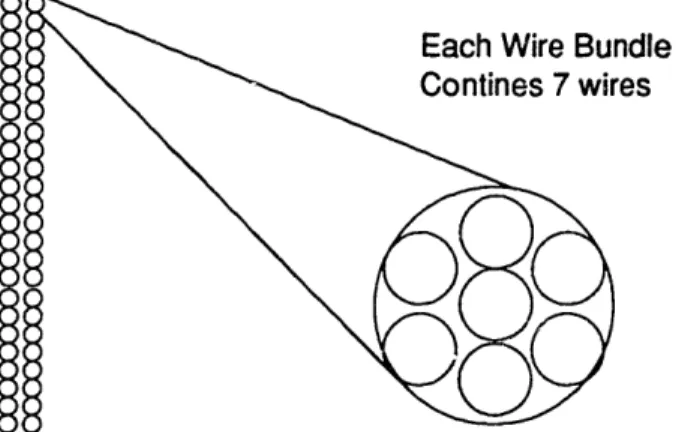
To allow for the different power configurations each of these 24 wires are then composed of 7 individual strands. This allows for innumerable
combinations of connection and increases flexibility in the power system. It also brings the total number of end connections to 168 and makes for a very
complex connector.
Figure 3-3 Magnified Litz Wire Bundle
was designed as a compromise, keeping as much flexibility as possible while limiting the complexity and size of the connector. The wiring pattern selected is illustrated below in Figure 3-3.
A1 in from track section or inverter
A2 A3 A - _ A4 A4' -A5 A 6 A7
A7' in from next trac section
A7' returns to previous track or from Al
section or back to inverter
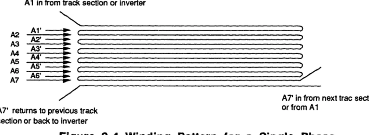
Figure 3-4 Winding Pattern for a Single Phase
Figure 3-3 shows the connection diagram for all seven strands of 1
complete phase (A, A'). All the wires of each phase are hard wired into each other with one wire left unconnected at either end. The corresponding phases (a, a',B,B'etc...) are each wired in the same pattern yielding 144 hardwired connections and 24 loose connections at each end of every track segment. This method of connection hardwires most of the individual wires, but leaves several different wiring schemes available from the power electronics stand point. This connection configuration is a good compromise between versatility and
complexity.
Because 24 wires are not hardwired, the track can be wired to the power inverters with all of the phases in parallel or in series. These configurations are illustrated in the following figure.
From Inverter A' B' C Y B F a b c d e f a' b' c' d' e' f' Return Series Figure 3-5 Parallel From Inverter A a B C D E Ft A B I
A'aBb
c'd
e
F'
Return Paralleland Series Connections
In the series connection the wires labeled with capital letters (A,B,C...) are connected at one end of the track to the inverter and at the other end of the track to their returns (A',B',C'...). This set of wires (A',B',C'...) then connects to the set (a,b,c...). After traveling the length of the track these wires connect to their returns (a',b',c'...) and complete the circuit back to the inverter. In this
configuration the current travels the length of the winding, returns, and then travels the length of the winding again. The series connection allows the power inverter to be run at higher voltages but with less current.
In the parallel combination both sets of wires (A,B,C..and a,b,c...) are directly connected to the inverter and immediately return to it through their primes(A',B',C'..and a',b',c'...). In this configuration the currents in the wires travels down and back all of the wires simultaneously with no interconnections. The parallel option allows the inverter to run at much lower voltages but higher
currents.
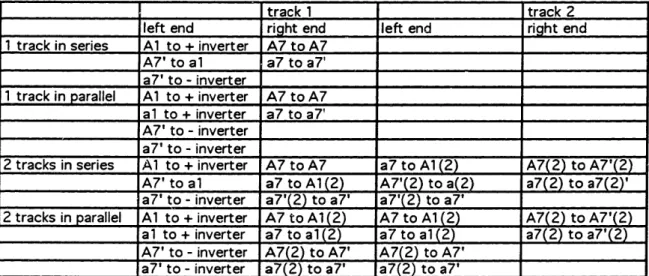
Because of the flexibility of this design, changes from series to parallel and vice versa are simply made by changing the connectors that attach to the track segments. Also, connections between track segments are easily made by jumpers, so that any number of track segments can be run off of each inverter. Finally, each segment of track is wired identically making for easy production. The following table best illustrates the connection schemes.
Table 3-6 Series and Parallel Connections for One and Two Tracks
3.4 The Electrical Connectors
Printed circuit boards are used to make the actual electrical connections, with the wires from the helical winding soldered to pads on the boards. This connection scheme provides an easy and reliable method of connecting the bulk of the wires. The "unconnected wires" for interconnection are also soldered to these boards and emerge in the form of a 24 pin right angle
track 1 track 2
left end right end left end right end
1 track in series Al to + inverter A7 to A7
A7' to al a7 to a7'
a7' to- inverter
1 track in parallel Al to + inverter A7 to A7
al to + inverter a7 to a7'
A7' to- inverter a7' to - inverter
2 tracks in series A1 to + inverter A7 to A7 a7 to Al (2) A7(2) to A7'(2)
A7' to al a7 to A1(2) A7'(2) to a(2) a7(2) to a7(2)'
a7' to - inverter a7'(2) to a7' a7'(2) to a7'
2 tracks in parallel Al to + inverter A7 to A1(2) A7 to Al(2) A7(2) to A7'(2)
al to + inverter a7 to al (2) a7 to al (2) a7(2) to a7'(2)
A7' to - inverter A7(2) to A7' A7(2) to A7' a7' to - inverter a7(2) to a7' a7(2) to a7'
connector. Interconnections are then made by making a 24 wire jumper cable with matching 24 pin connectors on either end. In practice, 50 pin connectors are actually used with two pins running to each wire on the track (48 wires) and 2 pins unused. Two pins per wire allow the track to function if one pin loses contact. Other reasons for selecting the 50 pin connector were size, ease of installation, and availability.
The circuit boards are mounted to the track by simple to manufacture mounting brackets made of plexiglass. The brackets are fastened to each other in much the same way as the guide rails are fastened; through the fiberglass core with 4-40 screws. An illustration of the final connector can be seen in
Figure 3-5, while detailed blueprints of the circuit boards and mounting brackets can be found in the appendix.
3.5 The Mechanical Clamp
The second component of the wire interconnections is a mechanical clamp. This part positions the wires flush to each other at the interconnections between track sections and fastens them securely in place. n electrical terms, it keeps the wires aligned geometrically to prevent "electromagnetic pot holes" at the junctions between track pieces. This alignment is important to maintain
continuity in the linear motor.
An illustration of this clamp and how it is installed can be seen in Figure 3-6. It consists of two deloren wedges that serve as guides for the wires and a bar for putting pressure on them. Two guides are used in pairs at each of the junctions. These guides rigidly maintain the angle of the wires so they can be pulled tightly without slipping. Since the wire from one track must pass over wire from the other track at the interconnection one guiding wedge is used with its
mt :U O
I-r I-r
a' In = u rb
L.0
4-U C C0
C :5 6. (n .. " M to .4) .Th 1 O -6 ' = CD )nX I y X.-0
+a U C)0
Iwu
.ar 4. 10 4) CDI-r
0
.. u-l -Un r0 w r-2o1 , r-. A0
=
0
L. la ._ L. (LQ
4a .Q . .-_ (( lc
-D:
4i (ZO
'2 '
(A .L 0)c .9 C) 0V .C (n *r E 6 .E . cr] "I VI 0) 0) CL C cu he m~~Cc
-~e -e0..a
cm,
_n Q Q~3 cn +uM tNE L'~t D r% U 0) rfi , ' .a E 10u
m :3a,
Q,.h
=1 i L. 0top facing upward while the other wedge is inverted to allow wire to pass under it. As a pair these guides insure geometrical continuity of both sections of wire and provide smooth surfaces to apply the pressure needed to hold the windings in position. The pressure is applied by a flat bar that focuses the force as close to the track windings as possible. Its blueprint can be seen in appendix 2. The clamp is flat enough to stay well out of the way of the magnets which pass over
it, while it is short enough to allow the vehicle to ride safely on only the brass channel that lips the edges of the guidance channels. Deloren was selected as the clamp material because it is rigid enough to hold screw threads yet soft enough not to damage the insulation on the wires as it clamps down upon them.
Blueprints for the wire clamps and guides may be found in the appendix.
3.6 Notes on Circuit Board Fabrication
A deal of experimentation was undergone in fabricating the prototype circuit boards mentioned in section 3.4 that should not go unrecorded. Instead of the normal photo-etching process commonly used to make circuit boards, a new process was tried where toner from a copy machine was used as a resist on the copper instead of the usual photoresist.
The circuit design was drafted on a computer CAD program and then printed on paper by means of computer printing and photoreproduction by use of a copy machine. This paper pattern was then placed over the copper of the board and the toner printed on the paper was remelted with an iron in an
attempt to transfer it to the circuit board. It was hoped that this toner would stick to the board and provide a thick layer of insulation that would resist the etchant used to dissolve the copper. Unfortunately, no usable results were obtained.
After some experimentation it is thought that by using different forms of paper or possibly a hotter iron and a lower temperature ink good results would follow. Because this process bypasses all of the darkroom steps in the photo-etching system, if this method could be improved it could considerably shorten the time used to make printed circuit boards as well as cut down the cost.
Since this method could not be refined within the time limit of this thesis, the prototype boards used in this track, were made by the standard
photo-etching process. Since there are a large number of boards needed for the entire track, and since there are 219 holes per board, it is recommended that the
boards be sent out to a professional manufacturer as this will easily offset the cost of labor of doing them in house.
Chapter 4
The Guideway Web
4.1 Number and Length of Track Segments
Although the dimensions of the track were specified at the beginning of this thesis, the real track could not be built to these exact specifications. This is because there is a finite pitch to the motor windings. Because we must maintain an integer number of pole pitches throughout the length of the track the
guideway segments must be built in multiples of three inches; a distance equal to the wavelength of the linear motor.
By comparing integer numbers of segments of various lengths to the overall length of the guideway it is possible by successive trials to calculate a length of track segment that both is a multiple of 3 inches (the pole pitch) and completes a 180 degree turn in an integer number of segments. 33 inch and 42 inch lengths both create total track dimensions of approximately the right amount. Of these two results, 42" was selected as the track segment length because it results in 32 total sections: 24 segments for the turns and 8 segments for the straight aways. Since 4 divides into 32 evenly, the 32 segment track
allows the four power inverters to each control an equal number of track segments (8). Replacing 4 of the curved pieces of track with the acceleration smoothing spiral transition curves leaves a final tally of 20 curved pieces, 8 straight pieces, and 4 spiral pieces.
It must be noted here that for manufacturing purposes the actual fiberglass guideway sections to be machined are 21 inches long: half of 42. Since 42 inches exceeds the travel distance of standard milling machines two 21 inch sections are machined and then assembled to form the 42 inch track segment.
To compensate for physical discontinuities that could be introduced at the interfaces of the track segments a brass c-channel is press fit along the top edges of the fiberglass web and along the outside lip of the two guidance channels. This brass stock smooths the ride for the vehicle and aligns the track
segments at their edges. If this brass stock is soldered into a continuous circuit around the track it may also be used to deliver power to the vehicle. A voltage can be applied between two of the brass loops, and like a conventional electric train set power can be sent to the bogey for its actuators and sensors.
Because the axles of the bogey are designed to slide out of their bearings and allow the vehicle to slip free of the track, neither the brass channel nor the other parts of the track obstruct the placement or removal of the test vehicle.
To further aid in alignment of adjacent track segments the top rail pieces are staggered so that they cross between different track segments and
physically bolt the two pieces together with screws.
4.2 The Straight Sections
and manufacture. Since the winding lies flat against the fiberglass center and runs its entire length, each straight sections can be laid out flat, drilled, and mounted from the dimensions of the guideway. The blueprints for the straight sections are included in the appendix.
4.3 The Curved Sections
The curved sections form the majority of the 180 degree turns of the track. They are made by taking sections of fiberglass web, drilling them accordingly and flexing them to form the appropriate arcs. Because the curves must be
banked to counter the centripital forces on the vehicle as well as bent to form the circular arc of the turn a complex set of geometric transformations
necessarily results in order to machine the curves in flat pieces and warp them into the appropriate angles and curves.
4.3.1 Banking
As the train rounds the circular curves at the ends of the oval track, to maintain its curved motion the vehicle requires a centripital acceleration
towards the center of the circular curve. Instead of using the guideway and the vehicle to counteract these forces, the turn is banked to use a component of the vehicle's weight to counter the forces created by the curve. This banking is
identical to that used for most highways and railroads and the necessary banking angle is relatively simple to calculate.
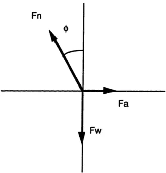
Figure 4-1 diagrams the forces on a vehicle of mass m and the directions
Fw is the weight (mg) of the vehicle acting downward and Fn is the force needed to counteract these forces. V is the velocity of the train while R is the radius of curve. G is gravity. We wish to find a banking angle e such that all the
forces are balanced for a constant velocity. Balancing the forces in the x and y directions we have:
Fn
Fa
Fw
Figure 4-1 Force Diagram of a Banked Turn
Fn cos(4) = Fw = mg
Fnsin(o) = mv2/R
Dividing these equations we find = tan'1(v2/gR). Working the calculations at
3m/s, 2.5 m/s and 2m/s with a radius of 4.075 meters gives bank angles of 12.9, 9.05 and 5.8 degrees accordingly. Since tests at the maximum velocity of 3 m/s as well as tests at lower velocities are desired, a compromised banking angle
of 10 degrees was selected. 10 degrees is an easy angle to work with and yields a velocity of 2.66m/s, close to the middle of the desired test speeds.
4.3.2 Fabrication Problems with Banking
Although the calculation of the banking angle is extremely straight forward, problems arise in manufacturing the banked turns. To understand these problems we consider the shape of the guideway in such a turn. When unbanked, the guideway has a specific height of 5 inches. As we bank this section the height tilts inward until the guideway reaches the banking angle. Thinking about the tilting in relation to the turn, for an angled guideway the top
now lies closer to the center of the curve while the bottom has been pushed further out. Thus, the turning radius at the top of the track is smaller than the turning radius at the bottom and the top and bottom edges of the guideway trace out different sized circles separated by the length of the web. The result is a cone with its vertex angle equal to twice the angle of the bank. If a pair of scissors is used to cut a strip from the bottom of the cone perpendicular to its axis, this cutting sill be in the shapeof the turned and banked guideway.
Positioning the vehicle as it would rest when in motion along the track, we can see that the vehicle rides along the top of this cutting throughout the turn. (see Figure 4-2)
The problem is building such a surface. To be milled and drilled
accurately the surface must be manufactured flat and then bent into the proper conical shape. Two things must be solved: First, we must determine the shape of the flat surface that will bend into the proper cone, and second, we must determine the mathematical transformation of points from the flat surface to the
Bank Anale(&)
Figure 4-2 Banked and Curved Guideway
conical one in order to properly place the screw holes that attach the top rail and the guidance channel.
4.3.3 Forming the Cone
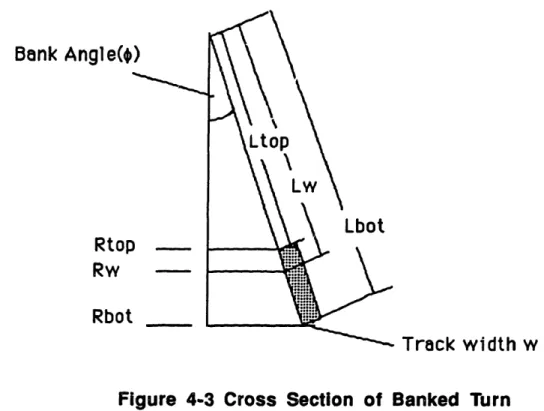
Consider the side view of the cone shown in Figure 4-3 where Rtop,
Rbot and Rw are the radii of the circular turn at the top of the guideway, at the
motor windings, and at the bottom of the guideway respectively. Since Rw is fixed by the circumference of the test track and a bank angle is 10 degrees is known by trigonometry we can calculate all of the other radii and their
Bank Angle(o
Rtop Rw Rbot
Figure 4-3 Cross Section of Banked Turn
corresponding slant heights Ltop, Lw and Lbot. We now establish the relation
between the dimensions of the cone and the dimensions of a flat surface that can be folded into this cone.
The first dimension that must be preserved is the slant height L. To achieve proper folding this height must correspond to the radius of a circle in the plane to be folded. Noting that the circumference of the track is determined by the radius R, the planar shape that can be folded into the cone becomes an arc along the circle of radius L that spans a distance equal to the circumference of the track at the radius of the turn. This transformation is best illustrated in Figure 4-4.
RAnkl Annla(&A
rntr1l Annla
L
Folded Cone Flat Section
Figure 4-4 The Flat Transformation of the Cone's Surface
Stepping through the math with the actual numbers for this diagram, we
find that Ltop is 922.869 inches while Lbot is 927.869. Dividing the
circumference of the track determined by the radius of curve by the
circumference of circle of radius Lw we find that the planar region that can be bent into the desired curvature is the circular section bounded by Lbot, Ltop, and the arc between them whose central angle is 62.51 deg.
4.3.4 Finding the Hole Locations
To keep the motor segments uniform along the track each curve segment is designed to have a length of 42 inches. Because the guideway conforms to the shape of a cone along the curved sections however, the guideways actual circumference varies with its slant height from a minimum at its top to a
circumference exactly 42 inches. Since the top rail and the guidance channel are fixed slightly above and below the windings, their circumferences are necessarily different than that of the windings. Using the same trigonometric relations described in Figure 4-3 the necessary lengths of channel can be determined as their vertical position on the guideway is known. Hole spacing is found by dividing the lengths of the rails by the number of holes. A complete list of calculations and screw hole coordinates appears in the appendix and on the top rail and guidance channel blueprints.
The more difficult problem involves properly placing the corresponding mounting holes for the top rail and the guidance channel in the fiberglass web of the guideway. This fiberglass web is a section of the curved planer figure displayed in Figure 4-4. The projection of this figure on to the rectangular block from which it must be manufactured is shown in Figure 4-5.
Origin (0)
Figure 4-5 Production Blank
The problem here is apparent. The screw holes for the top rail and guidance channel follow curved paths around the track segment but the
production blank must be indexed in Cartesian coordinates with reference to its origin O, This change of index involves several coordinate transformations described below.
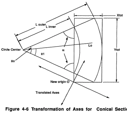
A segment of track with the appropriate geometrical relations is shown in Figure 4-6. 00 is the segment angle that can be found by dividing the total
angle of 62deg by the number of segments to be produced. 01 is an arbitrary angle opening from one side of the arc, Lo is a radius to the track of arbitrary length and Linner and Louter are the inner and outer radii respectively. Xtot
and Ytot are the overall lengths of the rectangular blank, and a is the angle the
inner radius makes when it intersects this rectangle.
Circle
ot
Translated Axes
Figure 4-6 Transformation of Axes for Conical Section
To determine the hole locations for the top rail and the guidance channel we first use polar coordinates with reference to the circle seen in figure 4-6 whose radius is equal to the slant height. We then translate this origin to the corner of the production blank titled "new origin" . Since the axes at this point
are still rotated from the Cartesian axes of the rectangle, we perform one final axis rotation and the holes can now be located with reference to the corner of the rectangular production blank.
To illustrate we will calculate some hole locations for the top rail. First we take an L of appropriate length to mark the center of the top rail. Using this as a radius and the central angle of the segment in radians, we can calculate the length of the rail that is needed. Dividing this by the number of holes to be drilled we can find the spacing between drill holes. Working backwards these distances can again be divided by the circumference to express the position of
the holes in (R, 0). R is equal to Lo and 01 is defined opening outward towards
e0 and increasing with hole distance.
We now need to write these polar coordinates using the left corner of the rectangle O as a new origin. We first change the polar location to rectangular coordinates and then shift the origin to point O. The mathematical
transformations required to do this are listed below. From polar to rectangular.
x = L cos(O)
y = L sin(9)
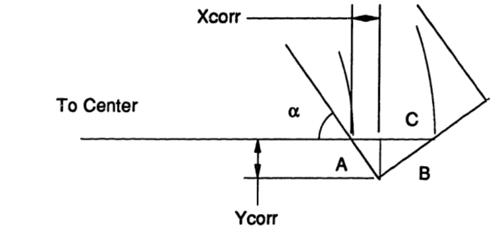
Establishing the new origin in reference to the current origin we use the diagram shown in figure 4-7. Xcorr and Ycorr are the displaced distances perpendicular to the polar radius R at 0 = 0. Triangle ABC is formed from the
radius Louter as it intersects the rectangular blank. Going back to figure 4-6 we see that by using the theorem for an isoceles triangle, we can write a in terms of the central angle with a = (180 - ) / 2. Using right triangle trigonometry to find
Xcorr
To
B
Ycorr
Figure 4-7 Finding the Origin of the Blank
sides A and B in terms of C we have:
A = C cos(ax)
B = Csin(a)
Since triangle ABC is similar to the triangle with sides of Xcorr and Ycorr there sides are proportional. Thus we have.
Xcorr = C cos2(a)
Ycorr = C cos(a)sin(a)
where C is equal to Louter - Linner or 5 inches which is the width of the guideway. Translating the new origin to this point we have
Xnew = Lo cos(O) - (Linner +Xcorr) Ynew = Losin(O) + Ycorr
The final problem that remains is that the coordinate axes from this new origin are in the same directions as the old set of axes. (see Figure 4-8)
New Axes
kxes
int (r ,e)
Figure 4-8 Rotation of Coordinate Axes
Since the rectangle we are mapping to is at an angle to these axes, we must rotate the coordinate system once again to index the points from the origin of the blank.
To achieve the necessary rotation displayed in Figure 4-8 we change the coordinates back into cylindrical using the relations:
x = r cos(O) r = (x2 + y2)1/2 y =r sin(o) = tan- (x/y) Rotating we have Xnew = rcos(0 + 3) Ynew = r sin(0 +,3)
We have now completed indexing the point with reference to the origin of the blank.
4.3.5 Final Layout
In summary, to find any point for a drill hole given the distance along the guideway we follow the following process. Find the angle 01 by finding the ratio of lengths along the circumference. Find the X and Y coordinates of that point. Write these points in terms of the translated origin O of the rectangular stock.
Revert back to polar coordinates and rotate the points so they are defined perpendicular and parallel to the rectangle's axis. Finally, convert to Cartesian coordinates to index the holes from the corner.
Since there are upwards of 25 holes, the actual calculations can be seen in appendix 1. An Excel spreadsheet program was used to calculate them numerically. Final tables of hole locations appear on the blueprints for the curved sections also shown in the appendix.
4.4 The Spiral Transition Curves
The spiral transition curves provide the link between the straight track segments and the circular curves. They are designed to linearize the change in acceleration felt bythe vehicle as it enters and exits the turns. The spirals are in the shape of a cubic parabola and are fabricated much like the circular curves.
4.4.1 Why use spirals
the straight track segments to the circular curves to prevent the vehicle from experiencing a jerk in acceleration at this interface. Analyzing the accelerations experienced by the vehicle as it moves along the guideway with constant
velocity a discontinuity appears in the acceleration normal to the direction of the vehicle's motion. As the vehicle crosses the boundary from a straight section to a curved one the acceleration in the normal direction instantaneously jumps from 0 to a finite value equal to the centripital acceleration m2 / R. This sudden
"step" in acceleration causes a jarring of the vehicle that is uncomfortable to passengers and can result in damage to the bogey. Transition curves are curves that gradually increase this normal acceleration along their length so that a ramp is seen in the acceleration between the straight sections and the curves instead of a step.
Mathematically, spirals, clothoids, limniscates, and cubic parabolas all provide gradual ramping of acceleration from 0 to a finite value. They are used extensively in Civil Engineering in setting out railways and superhighways and adapt well to the model MAGLEV track. Though these curves have subtly different shapes, for small angles they all approximate the cubic parabola. Therefore, this curve was selected to form the spiral transitions. The mathematics behind the cubic parabola is slightly simpler, and the curve provides exact solutions in x and y coordinates making it is easier to set out.
4.4.2 Acceleration in the Moving Frame
Before analyzing the properties of the cubic parabola a few definitions are necessary to understand the physics of the curve itself. Equations of
acceleration being determined from their derivatives. In the situation of the moving train it is more useful to observe the accelerations from the reference frame of the train itself. We would like to write the velocities and accelerations
not in terms of x and y but in terms of two new coordinates T and N, T which is parallel to the velocity of the moving body and N which is normal to it.
Fortunately, entire sections of vector calculus exist to do just this.
To understand the equations of motion we will introduce N, T, R, s, 4, and
K. Vector R locates the body exactly, T is the unit vector pointing in the direction
of the body's velocity, N is the unit vector pointing in the direction perpendicular to T. S is the unit parameter along the length of curve, is the angle made between T and the x-axis, and is a unit of curvature used describe the
curviness of a curve. This k is equal to the reciprocal of the radius of curvature.
In differential definitions we have T = dR/ds,N = dT/d 0, and K = d Ads. Figure
4-9 which follows illustrates these parameters geometrically.
Derivations of these differential relationships as well as the formula
Acceleration = Td2s +N(ds)
dt2 dt
are left to textbooks such as Simmons and Silvermans texts on differential calculus.
4.4.3 Equations of Motion for the Circle
path of partical along s
T -
dR/ds
Figure 4-9 Path of a Particle Through Space
the circle and along the spiral transition curve and proceed to match them. For the circle we have
Acceleration = Td
5+NK(ds)
dt2 dt
Where the equation of the circle is written as R = rcos(O)i + rsin(0)j, with i and j being the unit vectors in the x and y directions.
Since ds/dt is the velocity of the vehicle (distance traveled per unit time) the second derivative term in the acceleration formula goes to zero since the vehicle is traveling with constant velocity. Finding K we have
K = d4/ds. Since d4ds = de/ds and s = rO for a circle we have K = l/r.
Substituting back into the original equation we find that that the acceleration in the N direction is the only acceleration and it is equal to V2/r. Plugging our test
velocity of 2.66m/s into this equation we get an acceleration of 1.750m/s2.
4.4.4 Equations of Motion for the Spiral
The equation of motion for the spiral is slightly more complicated. The cubic parabola is defined as y = bx3 where b is a constant. Parametrizing this
in terms of t we have:
x=t
, y=bt
3R = ti + bt3j
once again the velocity, ds/dt. of the vehicles a constant so the only acceleration on the vehicle acts in the N direction. Solving for the NKc(ds/dt)2 term we must first find ic. Since = da/ds, parametrically we have:
taking
the
of
the
arctangent
derivative
we
get
taking the derivative of the arctangent we get :
do
1
dz
1 + z2
dz
xy
- yx
x2
substituting back yields:
d = 1 [xy - yx]
+ ()2
i2
x
and d =
where u substitution and the quotient rule were used to differentiate for K and the dot notation is used to represent d/dt. Applying this formula to the curve
x =
t,y
=
bt
3we have
x=t,
=1,
=0 and y= bt
3, y=3bt
2, y=6bt
so that
Kc= .6bt
[1 + b2t4]3/2
Since velocity through the curve is constant, the only change in the acceleration must come through changes in 1K. Graphing this curve for various b's we have
2.
1.
0.
0.5
1
1.5
Z
2.5
3
These curves represent the change in acceleration in the direction normal to the vehicle. From the graph in Figure 4-10 it is apparent that the curves initially have highly linear slopes until they peak and start to fall off around their middle. Since we want a linear change in acceleration that starts at 0 and ends at the
centripital acceleration of the curve (1.750m/s2) we should select the constant b to achieve this acceleration before the curves begin to fall off.
4.4.5 Length of the Transition Spiral
To determine the length of the spiral transition an acceptable rate of change of acceleration must be known. If the length of the transition is L and the velocity of the traveling train is V, the average change in normal
acceleration is the acc * V / L. Since the acceleration is given by V2/R we have
V3/LR as the rate of change of acceleration. Using Shortt's criterion for railroads found in Royal-Dawson's books on rail and highway curves the
minimum jerk that can be felt is 1 ft/s2 per second. Thus, the length of the spiral
becomes
Lm .0703 V3 Rm
where L and R are in meters and V is in kilometer per hour. Plugging actual numbers into this equation yields a spiral of length 15 meters. Given the size limitations of the test track, this distance is unacceptable. Fortunately, human comfort makes little difference in the model and since the track can easily withstand higher transition forces and there is no fear of vibration the transition
can be made in a shorter distance.
Calculating the length of curve for the spiral we have
d2 dy 2 ds = dt d +t, (d. dt withx=t, ;X=l,
s= (1
?o x=O and y = bt3, y = 3bt2, y = 6bt + 9b2t4)1/2dtThis integral is impossible to integrate, but numerical solutions can be found given b and the upper bound of integration. Because the calculated spiral is extremely flat a solution of approximately 42 inches in length can be found after a few trials.
Straight Section
Variable length X
I
Spiral to be Inserted
Where Curve was Removed
Figure 4-11 Insertion of Proper Spiral
ir Curve
Regarding Figure 4-11 to create the equation of this spiral first remove the 42 inch section of curved track that the spiral is to replace. Using the
endpoint of the matching straight as an origin, trigonometry gives the distance y that the spiral must climb to connect the straight section and the curve. We then plug in various values of x to the cubic parabola equation y = bx3 and solve for
the constant b.
solving for the length of the curve:
ds=
f
+(
dsdx
we continue to select lengths of x until we generate an arc that is Slightly smaller than 42 inches long. To maintain the 42 inch pole pitch the remaining distance of 42 minus the length of the spiral is simply pushed back up the straightaway.
Solving the equations for y with R equal to the radius of the turn gives
y = R(1- cos 15) y = 5.46645.
After several iterations selecting x's and generating curve lengths by numerical solution we find x = 40. Thus the length of the transition spiral becomes
40.6575, and its equation is y = .0000854133x3.
4.4.6 Construction of the Spiral
The problem with the building the spiral is constructing the shape that fits accurately between the straight pieces and the circular curves it is designed to
connect.
As the spiral follows its y=bx3 form in it planer dimension it must rotate
from an angle of 0 to the bank angle of 10 degrees along its axis. The flat transformation of this resulting curve is extremely complex, so that it is counter productive to construct this curve as the conical segments were.
Alternatively, the design for manufacturing shown in Figure 4-12 is taken. A piece of track slightly over 42 inches long is selected as a blank. The blank section is fitted into a 3 inch by 30 inch C-channel with its ends protruding from either end. 30 inches is long enough to clear both electrical connectors on the segment while the 3 inch width of the C-channel will accommodate the
deflection of the spiral. For support, 2 pieces of threaded rod are welded to the bottom of the c-channel and threaded into the bases of two guideway support clamps. A computer printout of the required spiral is generated and
the appropriate 30 inch length of this printout is pasted to the bottom of the C-channel. The blank guideway is positioned visually to the printout and held in
position by set screws placed at 1 inch intervals along the channel. The screws maintain the proper shape of the spiral throughout its length.
Once the blank is in position, it can be sanded down to butt up precisely with the adjacent straight and curved pieces. Once shaped, the motor winding is stretched across the channel blank and secured at the connectors. The hole locations of the necessary top rail and guidance channel are the marked using the winding as a guide and the rails as templates. The blank is drilled and the top rail and guidance channel are fastened to each other and screwed into
place. Since the markings from the template will not be 100 percent accurate, the holes are overdrilled to allow the screws that lock down the top rail and
en a, 4.a C (A *-I Q
0
en 7ra C Om X Zz
.1 V) C lp 0)fi a ens
Ela, C 0 E Q C cr LF I-0! C _ )u0E 0
E
X mN M * Un r N fL\E
F-a
I-U, l (Uu) C
0
C O U) C0
UN
I-UW 4.0
umCRJI U I.0
amE
0
u
0
- 'r 'a9guidance channel to fit through easily. The winding is then epoxied and taped like the rest of the sections of track. Blueprints for the C-channel appear in the appendices. A relatively heavy screw size was used to minimize screw