Design of a Wireless, Passive, Single-Use Emergency Call System
The MIT Faculty has made this article openly available.
Please share
how this access benefits you. Your story matters.
Citation
Staats, Wayne L., Dan P. Lorenc, Zihao Zhang, Ethan L. Huwe, Mark
M. Barineau, and Alexander H. Slocum. “Design of a Wireless,
Passive, Single-Use Emergency Call System.” Proceedings of the
ASME 2010 International Mechanical Engineering Congress &
Exposition, 12-18 November, 2010, Vancouver, British Columbia,
Canada, ASME, 2010. © 2010 by ASME
As Published
http://dx.doi.org/10.1115/IMECE2010-40681
Publisher
ASME International
Version
Final published version
Citable link
http://hdl.handle.net/1721.1/120080
Terms of Use
Article is made available in accordance with the publisher's
policy and may be subject to US copyright law. Please refer to the
publisher's site for terms of use.
Proceedings of the ASME 2010 International Mechanical Engineering Congress & Exposition IMECE2010 November 12-18, 2010, Vancouver, British Columbia, Canada
IMECE2010-40681
DESIGN OF A WIRELESS, PASSIVE, SINGLE-USE EMERGENCY CALL SYSTEM
Wayne L. Staats Dan P. Lorenc Zihao Zhang
[email protected] [email protected] [email protected] Ethan L. Huwe Mark M. Barineau Alexander H. Slocum
[email protected] [email protected] [email protected]
Massachusetts Institute of Technology, Department of Mechanical Engineering 77 Massachusetts Avenue, Cambridge, Massachusetts 02139 U.S.A.
ABSTRACT
In order to improve patient access to nurses during emergencies, a wireless wrist-mounted call button system was developed. The goal of this project was to create a simple, easy-to-use system that features a completely passive, wireless call button. Three major problems in existing systems – inability for patients to locate or reach the button, unnecessary user interface complexity, and the introduction of a potential vector for hospital-contracted illness – were addressed in the design. The wireless nature of the device ensures that it is always near the patient. A single-button interface considerably simplifies its use in comparison to multi-button systems, eliminating the possibility of incorrect button presses. Finally, the proposed call button uses inexpensive technologies and can be manufactured for such a low cost that it can be offered as a single-use device, eliminating the possibility of patient-to-patient disease transmission. Using radio-frequency identification (RFID) technology, patients are able to call for hospital staff from any location in the hospital that is covered by readers. The call button uses a passive RFID tag that can be turned on or off by a mechanical switch. A second tag is used to notify the system when a patient is out of range. The design was prototyped and tested, and future improvements are suggested.
INTRODUCTION
In order to improve patient safety, a reliable wireless call button was developed that is always within reach, simple to use, and single-use. These requirements were determined based on the shortcomings of existing call button systems. A solution
that uses available technologies was designed and prototyped; tasks are suggested to further refine the prototype.
A hospital emergency call button gives patients a fast and convenient way to communicate emergencies or needs to medical staff. The need for assistance is critical when a patient is in a life-threatening situation. Patients today have access to advanced hospital call buttons, such as that shown in Fig. 1 that can call for help as well as various other amenities. For example, some call systems can control a television while still functioning as an emergency call button [1]. Indeed, hospital response centers have seen improvements in the user interface and triage organization [2].
FIGURE 1. A TETHERED HOSPITAL CALL BUTTON WITH MULTIPLE FUNCTIONS. [1]
Despite the improvements in current systems, there are critical shortcomings that can potentially endanger patient well-being. Primary is the loss of access to an emergency call button during a life-or-death situation. Many current bedside emergency call buttons are either tethered to a wall mounted communication unit or attached to a panel close to the bed [3]. These buttons can easily become lost within the sheets or fall out of reach. In the severe case that a patient falls out of bed, the call button may be completely out of reach, leaving the patient helpless unless assistance is close by. Furthermore, a
patient who leaves the bed to use other hospital facilities such as a restroom undergoes a brief period without access to the emergency call system. Finally, tethered systems are a potentially dangerous nuisance because their cords can interfere with hospital equipment and become tangled with IV lines that are important for patient sustainment.
In response to this, some wireless systems have been developed [4]; however, all of these systems require batteries, which necessitates that periodic maintenance be performed to avoid loss of contact due to battery depletion and none have seen widespread hospital deployment.
Existing tethered and wireless call buttons are designed to be reused. Therefore, they must be sterilized before each new patient comes into contact with them. Reused components that encounter many patients can act as a vector for hospital transmitted illness. Also, careful quality control must be exercised in the hospital to ensure that each unit is properly sterilized prior to coming into contact with a new patient.
To further understand the issues surrounding the current hospital call buttons, current systems were surveyed and existing patents and papers researched. Designs were conceptualized and bench-level tests conducted to understand the capabilities of the relevant technologies. A novel device was developed that has the potential to improve patient well-being by keeping the button within reach, simplifying its layout, and eliminating the vector for hospital-transmitted infection.
OBJECTIVES
This project addresses the need to develop a new emergency call button that can replace existing hospital systems. The device seeks to reduce accidents, injuries, and deaths caused by issues with existing call buttons; several objectives were identified to fulfill this goal.
First, the call button should always be within reach of the patient. A wireless button attached to the patient would fulfill this objective; its signals would need to be picked up from all patient-accessible areas of the hospital facility, so reader placement would be an important consideration. Typically, wireless devices usually require battery power. A wireless technology that is completely passive would be ideal because the environmental, cost and reliability considerations associated with battery powered devices could be circumvented. Compatibility with magnetic resonance imaging (MRI) machines could also be improved by eliminating a battery.
Second, to prevent accidents and other unintentional problems, the call button must be unquestionably intuitive for users. Hospital caretakers often express concern about false positives, which waste their valuable time. The incidence of false positives must be minimized as much as possible in the button design.
Third, patients can become confused if call systems present them with a wide variety of buttons. To a patient who is not fully lucid and conscious of their actions, as may occur after
being anaesthetized, a call system with many buttons introduces an unnecessary source of confusion. Pressing the wrong button may trigger a call for the nurse when instead, for instance, the patient merely wants to turn on the television. Worse, if a patient requires a nurse and unintentionally hits a different button, a disastrous situation could ensue. Some call buttons even have a self-analgesic function. Clearly, the ideal call button should be intuitive, familiar and easy to use even under the most hurried conditions.
Fourth, the call button must be robust and should always work even after extensive use. It must be damage resistant: fluids associated with the hospital environment must not affect the operation of the call button. The call button should be either sterilizable or disposable to prevent infection.
Lastly, the patient must always be able to locate the call button. A tethered pendant causes entanglement and its location is not necessarily conveniently accessible to the patient. The button must be designed such that the patient receives adequate tactile feedback that indicates a successful press. Finally, after the button is pressed, the call system must provide confirmation to the patient that help is on the way.
TECHNICAL BACKGROUND RFID Basics
RFID, or Radio Frequency Identification, is the use of electronic tags for the purpose of identification and tracking using radio waves. These electronic tags are comprised of small integrated circuits (ICs) that can store and process information and larger antennas that send and receive wireless signals.
There are generally three types of RFID tags: active tags, which use a battery or other power source to aid in signal transmission; passive tags, which use no power source or battery; and battery assisted passive tags, which use an external power source to wake up the IC but have greater read range than standard passive tags.
In addition, RFID tags can be divided into two categories: Ultra-High-Frequency (UHF) and High Frequency (HF). UHF readers use radio frequencies at about 900 MHz; the corresponding UHF tags use dipole antennas to receive and reflect the signal from the reader. Dipole antennas must be tuned to the intended frequency; their resonant length is one half-wavelength of the carrier signal [5]. HF tags use magnetic fields and loop antennas. UHF tags are typically larger than HF tags but have higher read ranges.
The main components of any RFID system are the tags and the reader. The tags each contain a unique ID number and can be UHF or HF, and can be powered or passive. The readers contain a signal processing unit as well as an antenna that is used to power the tags and receive signals.
Prior Art
Columbia University Wristwatch Call System: Students at
Columbia University developed a concept that had a call button placed on the wrist of a patient [6]. Unlike a loose pendant
around the neck and torso, the “wristwatch” placement is relatively fixed to the body but can be quickly removed and reattached without disturbing the patient.
The Columbia project used RF communication at 315 MHz. While the communication method is unique, this piece of electronics requires advanced circuitry and production costs are on the order of $40 each. This price makes it cost-prohibitive as a single-use device.
Senior Care Facility Active RFID Call System: A senior
care facility in Orange, VA uses a wireless call system that contains a suite of buttons to call for medical assistants [7]. The wireless devices employ batteries to power their internal electronics. The system uses RFID as the wireless communication method. Transponders placed in every few rooms link with the central call station, which shows which patients need help and where.
This system seems to use RFID to accomplish the desired functions of a call system; however, the portable devices are reused and require batteries. Thus, sterilization is still required and the battery life must be monitored to prevent a loss of communication.
Passive RFID and Switching Mechanism (US Patent 7151455): This patent describes a system used to reversibly
activate/deactivate a passive RFID tag [8]. The passive RFID tag requires no battery – the reader relays signals that switch the tag on and off.
A standard, unmodified passive RFID tag is constantly in communication with a nearby reader, which picks up reflected signals from the tag. To deactivate the tag, the researchers who produced this patent developed a method that displaces the communicator chip from the signal-sensitive antenna. The reliability and effectiveness of this contact method is unclear, and it requires custom-made chip/antenna assemblies.
RESEARCH AND DEVELOPMENT
In order to demonstrate the feasibility and efficacy of using RFID for the call button concept, several experiments were performed. First, an effective way to switch the RFID antenna on and off was explored. An alternate idea for this, which was not pursued, will be briefly discussed. Second, the geometry of the antenna was altered to determine what parameters are most sensitive to the readability and signal strength of the chip-antenna assembly.
Antenna Switching Tests
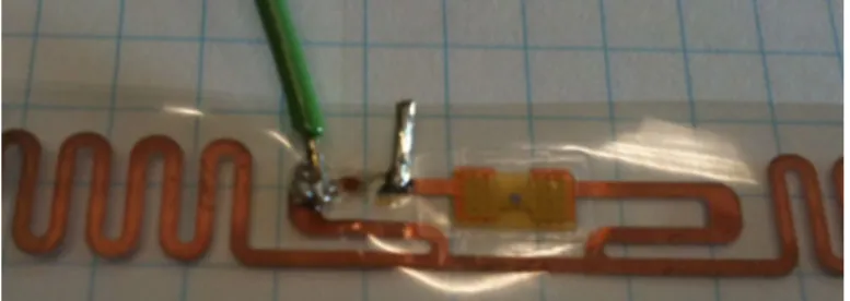
An effective means of breaking the communication between the RFID reader and the tag is a core element of the call button concept. The passive RFID tags used in these experiments consist of a small chip that is permanently adhered to a thin copper antenna that is printed on a transparent sheet of plastic. An example of one of these antenna-chip assemblies (referred to as the “tag”) can be seen in Fig. 2.
FIGURE 2. AN UNMODIFIED RFID TAG.
The tags are excited by RF signals sent from the reader. The reflected RF signal, altered by the chip, is picked up by the reader. It was postulated that, if the chip could be decoupled from the antenna, it would have no way of altering the incident signal and therefore the reader would not be able to sense its presence. To test this hypothesis, a computer with a TagSense MicroUHF RFID reader [9] was used to detect several altered tags.
Several tests were performed to determine (1) if decoupling the chip and the antenna results in a loss of the tag’s signal, (2) the simplest effective decoupling method, and (3) if it is possible to repeatedly recouple the chip and antenna after they have been decoupled. First, the antenna was cut in several locations to see if this resulted in loss of signal. It was determined that, indeed, an almost complete loss of signal results when the chip is decoupled from the antenna. Furthermore, the most effective break point was very close to the chip. To test if the connection between the chip and antenna could be reliably reestablished, a wire was soldered to each component, as shown in Fig. 3. When the wires were placed in electrical contact, the tag was readable by the reader. When the electrical contact was broken the signal was lost. Thus, it was determined that removing and reestablishing electrical contact between the chip and the antenna was a feasible method of varying the readability of the tag.
FIGURE 3. THE MOST EFFECTIVE CHIP/ANTENNA DECOUPLING LOCATION.
While the soldered wire connection was useful to demonstrate the switchability of an RFID tag, it is not very practical in an actual device. It was desired to instead use an off-the-shelf, mechanically latching pushbutton switch – this will be discussed further in the Design section. At first, replacing the soldered wire connection was unsuccessful. The reader would detect the tag regardless of whether or not the switch was closed. In fact, the chip must be decoupled from the antenna on both chip leads using a dual pole switch. At the frequencies that the antenna operates, “sloshing” of electrical current as well as capacitive coupling across the switch could result in unintended communication if only one of the leads is broken. Indeed, this was observed in some experiments.
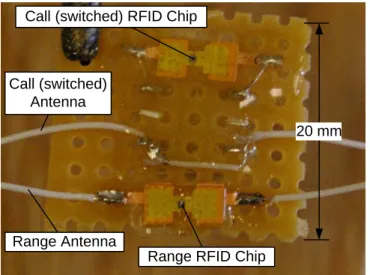
Additionally, the best results occurred when the length of wire between each chip connection and the switch was minimized. Some examples of prototype tags with switches soldered between the chip and the antenna can be seen in Fig. 4. Some notable features include the short length of wire between the chip and the switch and the potting epoxy that provides strain relief for the antenna wires.
Call (switched) RFID Chip
Call (switched) Antenna
Range RFID Chip Range Antenna
20 mm
FIGURE 4. A SWITCHED RFID TAG. THE UPPER CHIP IS SOLDERED TO A DPDT SWITCH. A LENGTH OF WIRE THAT
ACTS AS THE ANTENNA IS SOLDERED TO THE OTHER LEADS OF THE SWITCH. A SECOND TAG (UNSWITCHED) IS ALSO ATTACHED TO THE BOARD. EPOXY COVERS ALL
OF THE COMPONENTS FOR STRAIN RELIEF.
Shielding also proved to be an effective way to reduce the communication between the tag and the reader when the switch was opened. Aluminum foil, wrapped around the chip and the exposed wires between the chip and the switch, was effective at reducing unintended reads. This makes intuitive sense since the foil acts as a Faraday cage and prevents the electric field from affecting the leads near the chip and ensures that the antenna is the only part affected by the excitation from the reader. The foil shielding can be seen in Fig. 5.
As a side note, another idea was tested which may have utility as the device is commercialized and optimized for low cost. Instead of a mechanically latching switch, a bistable mechanism could be used. In essence, a beam that is confined between two walls (or a disc confined in a smaller cylindrical cavity) exemplifies the bistable mechanism. When a certain force is applied at the midpoint of the beam, it elastically buckles into a second stable orientation. This concept could be used to make electrical contact between the chip and the antenna. Several potential embodiments of this were conceived, including one in which the antenna is integrated into the bistable element. The force required to buckle the beam can be calculated according to Vangbo [10]. An experiment could be run to actually determine the proper force and throw according to the feel. 20 mm Foil Shield Call (switched) Antenna Range Antenna
FIGURE 5. FOIL SHIELDING APPLIED OVER THE CHIP TO REDUCE UNINTENDED COMMUNICATION WITH THE
READER.
The advantages of the bistable beam configuration are that the relatively high cost of a mechanically latching switch could be removed. Also, the thickness of the bistable element would almost certainly be lower than a mechanically latching switch, which would result in a thinner overall profile for the device. A major disadvantage, however, is that the switch would have to be mechanically reset after it is pressed by the user. In contrast, the mechanically latching switch can be pressed over and over again, and its state reset in the system’s software.
Signal Strength Tests
The foil-printed antennas proved to be difficult to work with in terms of packaging. Theoretically, a dipole antenna only requires a length of wire to function properly – i.e. the geometrical pattern of the foil-printed antenna is not integral to its performance. Several tests were performed to determine (1) the effectiveness of using a conventional stranded wire rather than the typical foil-printed antenna, (2) the length of wire that resulted in the best signal strength, and (3) how sensitive the signal strength is to changes in distance from the reader and geometrical orientation.
A properly tuned length of wire proved to be an effective substitute for a printed antenna. Experimentally determining the optimal antenna length was accomplished by soldering two 20 cm wires to either end of a switched RFID chip. This created an RFID assembly with an extra long antenna of 40 cm plus the additional length associated with the switch the leads going from the switch to the chip. The RFID assembly was then placed near a UHF RFID reader that measured the signal strength of the tag. The antenna was cut in 1 cm increments. The results of this test can be seen in Fig. 6. It was observed that the antenna showed peaks in the signal amplitude at lengths of 130 mm and 460 mm. This showed that a total antenna length of around 130 mm was nearly an optimal length for the device. Accounting for the additional length of wire in the switch and associated leads, this is very close to the expected half-wavelength resonant length of 159 mm. The second peak in the signal amplitude occurred at a length that is
close to 1.5 wavelengths, which corresponds to the second resonant mode of the dipole antenna.
Using the results of the antenna length test, a tag was constructed with a resonant-length antenna to test the signal strength in various orientations. First, the signal strength variation with distance from the reader was measured. As expected, the signal strength decayed approximately as the inverse-square of the distance. This can be seen in Fig. 7. It is thought that the small increase in signal strength at the farthest distance can be attributed to the proximity of a wall at that point. This seems to suggest that a small, confined space (such as a hospital room) could be advantageous to the readability of the RFID tags.
The orientation of the tags had an effect on their readability, also. The tags experienced poor readability when the axis of the (straight) antenna pointed toward the reader. This could potentially be alleviated by introducing a tortuous path into the antenna, thereby exposing some perpendicular segments to the reader at all times. Another effect that must be investigated more is the influence of the proximity of the human body. This drastically reduced signal strength, potentially due to the significant dielectric properties and lack of complete RF transparency of the human body. Upon conversing with RFID researchers, it is believed that the antenna can be retuned to a new resonant length that operates effectively near the human body.
FIGURE 6. SIGNAL STRENGTH VERSUS MEASURED ANTENNA LENGTH. RESONANCE WAS OBSERVED AT 1/2
AND 3/2 OF THE CARRIER SIGNAL WAVELENGTH.
FIGURE 7. SIGNAL STRENGTH VERSUS DISTANCE FROM READER.
DESIGN
System Architecture
The system is divided into three main components: the wrist call button, the wall-mounted reader and the nurse’s station. These three layers provide both fail-safety and flexibility, allowing the system to be easily configurable and provide a high level of safety to patients. A flowchart depicting the system’s operation is shown in Fig. 8.
The wrist call button is comprised of two RFID tags. Using two tags rather than one allows the system to differentiate between a system malfunction and a call for help. In the normal state, only one RFID tag in the wrist call button is activated. In the emergency state, both RFID tags are activated. If the user wanders out of range, one or both tags are activated but the reader detects no tags.
The reader serves two purposes: detecting wrist call button presses and housing a second button accessible to anyone in the room. Both wrist call button presses and wall button presses notify the nurse’s station of an emergency.
The nurse call station is wired directly to each wall unit and contains a display of patient status and information. A demonstration of this display is shown in Fig. 9. Emergencies and patients that have wandered out of range of the system are displayed to the nurses and can only be removed from the system when the situation has been remedied. In addition, the system can store useful information such as where a missing patient was last seen and how often certain patients call for help.
Pushed? Wristwatch Button Wristwatch Range Tag Wall Station Button Detected? OK Emergency Out of Range YES NO YES NO
Nurse’s Station
Wristwatch
FIGURE 8. A FLOWCHART OF THE PROPOSED NURSE CALL SYSTEM.
FIGURE 9. THE NURSE CALL STATION USER INTERFACE, SHOWING TWO PATIENTS CHECKED IN, ONE OF WHOM
HAS CALLED FOR HELP.
Wrist-Mounted Remote Call Button
The primary reason for introducing the wrist-mounted call button is its portability and ease of access to patients. The wrist-mounted unit, by design, is very difficult to become detached from the patient. To minimize false positives, the pushbutton was designed such that the exposed surface lies flush with the hard casing of the call button. The button on the wrist-mounted unit consists of a flexible elastomer membrane and a hard center plate that contacts a mechanical switch mounted on the encased PCB. A 3D model of the wrist-mounted unit can be seen in Fig. 10.
To ensure that the wrist-mounted unit is waterproof, an elastomer overmolding technology should be employed; however, for prototyping purposes, two separate parts of the casing were press-fit together and sealed with epoxy. The casing contains a PCB to which the chips, antennae and switch are mounted. Below the hard casing is a wristband that fixes the call button assembly to the patient’s wrist. The wristband contains a slot on each side to attach either a Velcro strip or an alternate fixation device. In future versions of the device, the
wristband could be replaced by a standard hospital ID bracelet to reduce cost. All materials considered minimally attenuate RF signals. An exploded view highlighting the design of the prototype wrist-mounted call button can be seen in Fig. 11.
The prototype, shown in Fig. 12, is split into separately-manufactured components that are joined with epoxy. The switch and RFID assembly described above is glued to the base of the main casing. In a production version, the entire assembly would be overmolded over the PCB, sterilized, and placed in sealed, sanitary plastic bags. The call button is intended to be single-use, thereby eliminating the vector to spread infectious disease from patient-to-patient.
FIGURE 10. THE PROPOSED WRIST-MOUNTED CALL BUTTON DESIGN.
FIGURE 11. AN EXPLODED VIEW OF THE PROPOSED WRIST-MOUNTED CALL BUTTON DESIGN.
FIGURE 12. THE PROTOTYPE WRIST-MOUNTED CALL BUTTON.
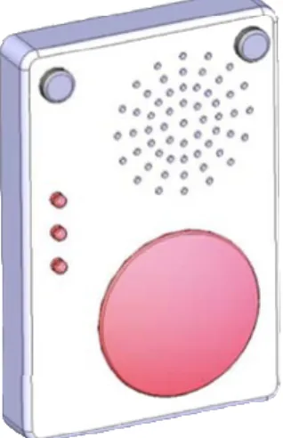
Wall-Mounted Call Station
The wall-mounted unit, shown in Fig. 13, contains a large emergency button, several status indication LEDs and a speaker. The emergency button can be used in case the wrist call button malfunctions or is inaccessible to a third party present in the room during an emergency. For example, if the patient has a seizure or falls unconscious, someone else could press the wall button rather than looking for the patient’s wrist-mounted button. The emergency button is designed to be noticeable and easy-to-find.
The status indication LEDs and a tone confirm for the patient that a call for help has been received by the system, when a nurse is on the way or when the patient is out of range of the system. Since there is no feedback on the call button itself, these LEDs are required to let patients know help is on the way. The button does not have LEDs because it does not have a battery to provide the power required for their operation.
FIGURE 13. THE WALL-MOUNTED CALL STATION, WHICH CONTAINS AN RFID READER TO COMMUNICATE WITH THE
WRIST-MOUNTED BUTTON.
The speaker can be used as a two-way intercom to communicate with the patient while dispatching a nurse or to triage the problem. Additionally, as mentioned, the system can give an auditory confirmation that help is on the way upon receiving a call from the patient’s wrist-mounted unit.
FUTURE WORK
The proposed system was designed to serve as a proof-of-concept for a passive RFID-based nurse-call system. Future improvements include design for high-volume manufacturing as well as developing a larger suite of solutions accessible to all patients.
The call button described here is designed to be a single-use product, and thus it must be manufactured at a low cost. It is projected that a production cost of a few dollars can be achieved with improvements of the current design. This is primarily due to the low cost of RFID components, which have been widely commoditized and used in many other industries. In the future, the bezel and other components of the wrist-mounted call button could be designed to be injection molded, thereby reducing their cost. In addition, the switch currently employed in the wrist-mounted unit could be replaced with a less expensive option. Redesigning the current switch would allow the size and profile of the call button to be reduced, which would reduce the overall thickness of the device.
Improvements in the RFID components could also be realized. For the prototype, the antennas are simple insulated wires that run along the wristband. The production model could instead use a polymer-coated printed antenna that could potentially increase RF signal reception and range while lowering the cost. Another option that could improve the performance would be to integrate the switch into the RFID chip. In production volumes, it would be possible to design the RFID chip with features that make switching the chip on and off very simple and reliable. Finally, the passive RFID tags used in the experiments had a limited range. According to RFID experts from the MIT Auto-ID Lab, battery assisted passive tags could greatly improve the range. The battery associated with battery assisted passive tags is typically small enough to be printed on a plastic film. This technology certainly merits further research.
Currently, the call button is designed as a wrist-mounted unit that is worn by the patient. However, because the internal electronics of the existing call button are small and compact, the core technology that was developed is highly modular. Another embodiment that could be developed is a call button pendant that can be worn around the patient’s neck. Initial user study has indicated this would be an appreciated option, but further user input and testing is necessary. Furthermore, other embodiments could be developed for patients with additional limitations, such as paraplegics or patients needing other specialized solutions. Such solutions may need to be activated by means other than a push button and may need to be situated in another location that is accessible to the patient.
While some significant design improvements and considerations are needed, the proposed hospital call button system has the potential to significantly improve the overall hospital experience for inpatients and better ensure patient safety and health.
CONCLUSION
The development and prototyping of an improved call button system has shown that the single-use, passive, wireless concept merits further work and refinement. The critical modules of the design were tested and demonstrated to work, although some additional engineering effort is required to improve the range.
A review of current systems demonstrated that a single-use, wireless system would be beneficial. The proposed system addresses this need. It uses a wrist-mounted device with two passive RFID tags, one of which is switched, to establish communication with a wall-mounted unit that is connected to the nurse’s station. When a patient calls for help by pushing the button the switched RFID tag changes state. The wall-mounted unit detects this change and alerts the nurse’s station, which displays patient statuses to hospital personnel in a simple, easy-to-understand format.
The system’s wireless functionality, which requires no batteries, allows the button to stay attached to the patient and prevents the possibility of an out-of-reach or lost button. The wrist-mounted unit only contains a single button so patients can use it without being confused by other non-emergency functions. The extremely low cost of RFID tags allows the entire wrist-mounted unit to be inexpensively produced so that it can be considered single-use, thereby eliminating the danger of a patient contracting an illness from the call button.
ACKNOWLEDGMENTS
The development of this device was done as a term project in MIT Course 2.75: Precision Machine Design. We are grateful to Lynn Osborn and Dr. Tom Brady of The Center for Integration of Medicine and Innovative Technology (www.cimit.org) for providing support for course 2.75 and this project; and the Brigham and Womens’ Hospital of Boston, MA. CIMIT support comes from DOD funds with the FAR 55.227-11. Additionally, the inspiration for the project was provided by Dr. Matthew Liang. Professor Alex Slocum, Dave Custer, Conor J. Walsh and Nevan C. Hanumara provided valuable, insightful guidance throughout the project. The MIT Auto-ID Lab provided testing equipment and valuable advice. Finally, the authors would like to thank the SolidWorks Corporation for providing the software used to create the solid models for this project.
REFERENCES
[1] “Series 7 Plus Pillow Speaker Advantages” http://www.anacom-medtek.com/pdf_files/ps.pdf
[2] Runy, L., "As They Become More User-Friendly, Hospitals Will Speed Adoption," Healthcare's Most Wired,
http://www.hhnmostwired.com/hhnmostwired_app/jsp/articledi splay.jsp?dcrpath=AHA/PubsNewsArticleMostWired/data/03F ALLMW_FEA_Wireless_Applications&domain=HHNMOST WIRED
[3] "Information Technology, TV/AV Equipment, Nurse Call Systems, Security, Television/Nurse-Call Remote," Heathcare Building Ideas, http://www.healthcarebuildingideas.com/ME2/Sites/dirmod.asp ?sid=&nm=&type=Publishing&mod=Publications%3A%3AAr ticle&mid=8F3A7027421841978F18BE895F87F791&tier=4& id=DFE605057A6D458382E16BE5F39D3860&SiteID=B824 D3634E9D4CAB8727A06DEA33A46
[4] “MicroVision 200® Wireless Nurse Call System,” Systems Technologies , Inc.,
http://www.wirelessnursecall.com/mvision200.html [5] Orfanidis, S. J., 2008, Electromagnetic Waves and
Antennas, http://www.ece.rutgers.edu/~orfanidi/ewa/ch16.pdf, Chap. 16, pp. 638.
[6] Luan, J. et Al., “A More Reliable Call Button Set-Up at Amsterdam Nursing Home: Final Report,”
http://community.seas.columbia.edu/cslp/reports/spring08/callb uttoncallbutton.pdf
[7] Swedberg, C., “Answering the Call at Senior Care Facility,” RFID Journal, http://www.rfidjournal.com/article/view/5262/ [8] Lindsay,J. D., Velazquez, H. F., Chen, F., Wagner, E. F., US Patent 7151455, 2006.
[9] TagSense, Inc., 2007, “TagSense Micro-UHF RFID Reader Data Sheet v1.8,”
http://www.tagsense.com/ingles/products/products/Micro-UHF.pdf
[10] Vangbo, M., 1998, “An Analytical Analysis of a Compressed Bistable Buckled Beam,” Sensors and Actuators A, 69, pp. 212-216.
APPENDIX A
ADDITIONAL DESIGNS NOT PURSUED Momentary Latching Circuit
Tactile domes are momentary switch contacts that provide reliable switching and positive tactile feedback. Tactile domes are very thin and inexpensive, making them ideal for our single-use application. In addition, they are also available in an almost endless array of sizes and actuation forces.
Tactile domes utilize the principles of buckling to operate. In the normal state, a tactile dome is a rotationally symmetric sheet of metal curved to resemble a dome. Once depressed, the dome buckles into its second mode of buckling, the shape of which resembles the letter “m”. The outer ring of the dome is connected to one input, and the space under the center of the dome is connected to a second input. The two inputs are connected when the dome has buckled, but remain disconnected if the dome is in its normal state.
There are several ways to use a tactile dome to activate and deactivate an RFID tag. The first and simplest approach places the tactile dome directly between the chip and antenna. The tactile dome switch is normally-open, so in the normal state the tag is disabled. When the dome is pressed, it buckles into its second mode of bending and activates the tag by connecting the chip to the antenna.
This method, while very simple, is non-ideal due to the momentary nature of the switch. The RFID tag will only be enabled while the patient is pressing down on the button, on the order of .1 seconds. In order to ensure the call for help is registered by the system, the tag must be activated for at least 3 seconds, a time limit not possible with only a tactile dome.
In order to increase the length of the tag activation from .1 seconds to 3 seconds or higher, an electronic latching circuit is required. The purpose of this circuit is to detect when the tactile dome is pressed and to keep the RFID tag activated for some period of time after. Unfortunately, there is no way to build this circuit passively. A battery is required for the latching circuit which increases the complexity and the cost of the overall system.
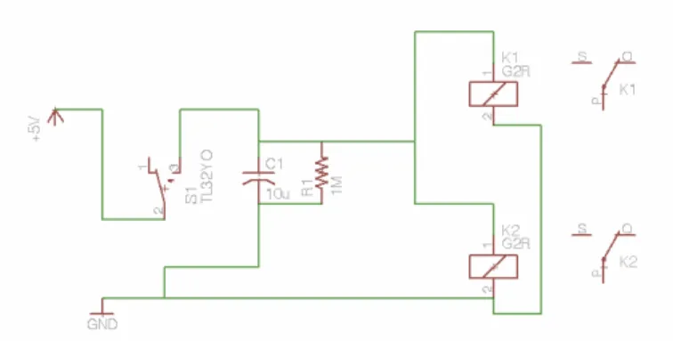
Standard switching mechanisms such as MOSFETs or BJTs will not work in this application because the load being switched is radio frequency. Due to this, the electronic switching must be performed using a solid state relay (SSR) or a special radio frequency switch. The preliminary circuit design is shown in Fig. 14.
FIGURE 14. A SCHEMATIC OF THE MOMENTARY LATCHING CIRCUIT.
The circuit uses a resistor-capacitor loop for the time delay, and drives the solid state relay using the voltage from this loop. When the relay is open, the antenna is connected to the chip and when the relay is closed, the antenna is disconnected. The circuit is activated using the momentary switch and the battery. When the switch is depressed, the battery charges the capacitor instantaneously. Releasing the switch allows the capacitor to discharge over the resistor and power the relay.
APPENDIX B Button Height Tests
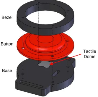
Ergonomic experiments were conducted to help determine an appropriate button height with respect to the bezel for the wearable button. The experiment to determine the button height was conducted using a simplified version of the wrist-mounted concept, which is shown in Fig. 15. Flexible buttons (the red part in Fig. 15) of several different heights were printed using SLA and assembled into an acrylic housing (the black parts) that had been laser cut to shape. The button heights were chosen to be 1 mm below the bezel, flush, and 1 mm above the bezel. A tactile dome was then placed on the inside of the button to make contact and provide tactile feedback. The mock button assembly was strapped to a user’s wrist. The qualitative results of this experiment showed that the highest button provided the best button feel for the user, the sub flush button provided the fewest false alarms, and that the flush button provided a good compromise between the two. Once the wrist-mounted design is finalized, additional ergonomic testing is recommended. A broader user cross-section and a more quantitative test could provide insight that would help to make the final design more user-friendly.
Bezel
Button
Base
Tactile Dome
FIGURE 15. A TEST TO DETERMINE THE INFLUENCE OF BUTTON PROTRUSION ABOVE THE BEZEL.
![FIGURE 1. A TETHERED HOSPITAL CALL BUTTON WITH MULTIPLE FUNCTIONS. [1]](https://thumb-eu.123doks.com/thumbv2/123doknet/14685666.560193/2.918.531.814.714.854/figure-tethered-hospital-button-multiple-functions.webp)