Publisher’s version / Version de l'éditeur:
Vous avez des questions? Nous pouvons vous aider. Pour communiquer directement avec un auteur, consultez la
première page de la revue dans laquelle son article a été publié afin de trouver ses coordonnées. Si vous n’arrivez pas à les repérer, communiquez avec nous à [email protected].
Questions? Contact the NRC Publications Archive team at
[email protected]. If you wish to email the authors directly, please see the first page of the publication for their contact information.
https://publications-cnrc.canada.ca/fra/droits
L’accès à ce site Web et l’utilisation de son contenu sont assujettis aux conditions présentées dans le site LISEZ CES CONDITIONS ATTENTIVEMENT AVANT D’UTILISER CE SITE WEB.
Internal Report (National Research Council of Canada. Division of Building Research), 1960-10-01
READ THESE TERMS AND CONDITIONS CAREFULLY BEFORE USING THIS WEBSITE. https://nrc-publications.canada.ca/eng/copyright
NRC Publications Archive Record / Notice des Archives des publications du CNRC :
https://nrc-publications.canada.ca/eng/view/object/?id=c29c7c30-5317-4286-acdc-b2fd3a3e182e https://publications-cnrc.canada.ca/fra/voir/objet/?id=c29c7c30-5317-4286-acdc-b2fd3a3e182e
NRC Publications Archive
Archives des publications du CNRC
For the publisher’s version, please access the DOI link below./ Pour consulter la version de l’éditeur, utilisez le lien DOI ci-dessous.
https://doi.org/10.4224/20386572
Access and use of this website and the material on it are subject to the Terms and Conditions set forth at
Spread of fire in corridors: a progress report
NATIONAL RESEARCH COUNCIL
CANADA
DIVISION OF BUILDING RESEARCH
SPREAD OF FIRE IN CORRIDORS
(A Progress Report)
by
J.H.
McGuireInternal Report No. 205 of the
Division of Building Research
OTTAWA
PREFACE
The results of a series of flame spread tests on a one-quarter scale model corridor having materials of various flame spread indices on floor, walls and ceiling are now reported. This work was carried out to provide a basis for further understanding of the significance of flame spread indices, particularly in relation to spread of fire along
corridors, and to show the influence of different combinations of floor, wall, and ceiling surfaces. It is now planned to extend the study in the near future to a corridor model of
normal dimensions. The author, a research officer with the Fire Research Section, has a special interest in the spread of fire.
Ottawa
SPREAD OF FIRE IN CORRIDORS (A Progress Report)
by
J.R. McGuire
For fifteen years or so tests have existed by which materials can be given comparative ratings so far as their spread of flame characteristics are concerned. Although the various tests impose different conditions, the sequence in which materials are listed in order of merit, for each of the tests, is very similar. It would ウ・・ュセ therefore, that the tests are generally valid in so far as they determine which materials will more readily propagate fire.
Precisely how the results of such tests sho'uld be applied has been in some doubt. The average room, hall or other
compartment of a building almost invariably has sufficient combustible material in it to allow a fully developed fire to become established. The nature of the building materials and contents will certainly be a factor influencing the likelihood of such a fire and the time it takes to develop. The relation-ship is so complex, however, that no quantitative analysis
capable of universal application has yet been derived. Nevertheless one case, the corridor, merits special attention for two reasons. Firstly, it often plays a substan-tial part in the spread of fire from one compartment to another, and secondly it is almost unique in that it can have very few combustibles in it and hence can be designed so that it will not of itself sustain a fully developed fire.
The desirabtlity of such a design of corridor must not be related to the question of the escape of occupants in the immediate vicinity of the origin of a fire but rather to res-tricting the spread of fire within buildings. Where lining
materials with a moderate or low flame spread rating are involved, conditions in a corridor usually become untenable due to smoke or heat before the lining materials bavebecome appreciably involved in the fire.
The object of designing a corridor which would not of itself sustain a fully developed fire would be to reduce the rate of spread of fire throughout a building. This function is similar to that of fire resistance which is to confine a fire to
2
-a p-articul-ar comp-artment. The choice of flame spread 」ィ。イ。」セ
teristics discussed above would thus perform the same function as firefighting in restricting a fire to dimensions even less than those of a fire resisting compartment. Such action might well reduce the life hazard associated with smoke and heat which could exist in neighbouring 。イ・。ウセ particularly those on the floors directly above the source of the fire.
The object of the studies that are here reported is to determine which combinations of ヲャッッイセ wall. and ceiling
lining materials, in a 」ッイイゥ、ッイセ will sustain and propagate a fully developed fire. The work is not yet completed and this report is merely a statement of progress to date.
Experimental Method
At the outset of the work it was appreciated that
between 20 and 100 tests would be required and that some decision was called for as to the dimensional scale to be adopted for the
experimental work. An investigation confined to the full
scale would have proved expensive and could not have been carried out within any of the NoR.C. laboratories0 Control of the
con-ditions would thus have been difficult and experimental work out of doors would have been virtually impossible during the winter months.
A dimensional scale such that experiments could be conducted in an enclosed burn area of the Fire Research l。「ッイ。セ
tory was chosen and the test apparatus illustrated in Fig 1 was constructed of asbestos board and angle irono It consists of a model corridor from which a model room openso For each test the latter was completely lined with fibre"insulation board to give a rapidly developing fire which was initiated with
50ce of gasoline. The corridor was lined with the materials being investigated and the primary observation was the progress of the fire at floor level. Where incombustible flooring was used a "marker" strip of セセ by セセゥョッ timber was laid along the length of the centre of the corridor.
The distribution and size of the vent openings were determined by the requirements that the corridor should be subjected to a severe fire exposure from the fire in the room and that the conditions in the corridor should represent the most favourable for the propagation of fire that would be commonly expected in practice. The first requirement was met by having one vent, between the room and the exterior, at a
3
-low level so that the exhaust gas f-low in the room was in the direction of the door opening to the corridor. In meeting the second requirement the size of the openings was governed by the principles out1inrlin Appendix A.
Preliminary tests were carried out to ensure that satis-factory test conditions had been established. About 40 seconds after the primary ゥァョゥエゥッョセ the room was completely involved in fire and flames were impinging on the ceiling lining material of the corridor and emanating from the upper vent at that
end of the corridor. Within about two minutes the floor of the corridor or the marker on the floor ignited. Where the corridor was lined only with incombustible materials the flames from
the primary fire only extended along a small proportion of the length of the corridor ceiling. These were the required test conditions so far as the primary fire was concerned.
When flammable lining materials were used it was found that a fully developed fire would progress rapidly to the
end of the corridor within about 3 minutes. During the main series of tests the influence of ventilation often appeared to be more important than was indicated by the preliminary tests. Thick smoke was common and occasionally an oscillatory alternation between growth and decay was evident.
When some borderline combinations of materials were tested it was found that a fully developed fire could progress qUite rapidly along the greater part of the length of the
corridor and yet not completely involve the last few inches of the floor. Since this phenomenon was solely associated with the abrupt change in conditions at the open end of the corridor9
an assembly was described as "f'at.Led" if the fire at floor level reached a point 18 in. from the end of the corridor. Observations were discontinued either when the fire reached this point or when
it died out.
Results and Discussion
The results obtained to date are given in Table I. They are of themselves, of course9 of some interest but in
the form given they only refer to the particular combinations of materials tested. With a view to making the results more Widely applicable, consideration has been given to the
derivation of a composite spread of flame index relating to the whole assembly and based on the ASTM fire hazard spread of flame indices for the materials involved. These indices
- 4
セwere obtained from manufacturers p from UnderwritersV Laboratories
lists and from an independent research Laboret ory, In several instances the index related to a type of material and not directly to the product usede
Composite indices were derived by summing arbitrarily weighted values of the flame spread indioes for floorp wall p
and ceiling lining materialso The validity of this approach depends on the linearity of the flame spread index scale and since it is scarcely possible even to desoribe the quantity or quantities measured by the flame spread index it is not possible to discuss this question theoreticallyo
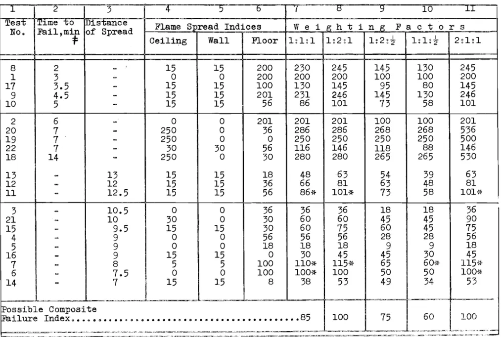
Several composite indices using different weighting
factors are listed in Table II o The rows of the Table that have been underlined relate to two identioal testso Because one
defined the combination as baving failed and the other as
having passed p the results are borderlineo The common composite index in these two cases is thus particularly signif:tcanto
Column 7 of Table II has been derived by adding together the indices for the individual materials o If the failure value were arbitrarily defined as about 86 then two of the test
assemblies which were found to be satisfactory would be defined as unsatisfactoryo
Column 8 of Table II has been derived by adding together the ceiling and floor indioes and twice the value of the wall index0 Although one of the results is inconsistent9 this ー。イエャNセ
cular approach has practical appea19 from the point of view of
simplicityp since the weighting factors correspond to the area ratios and the composite index if divided by 4 may thus be 、・ウセ cribed as an average index p averaging being on an area basiso
Column
9
might also be described as having an area basis exoept that the floor oovering is oonsidered to be l.ess signifioant by a factor of twoo It is the most interesting approach to the problem since it gives no inconsistent resultsoColumns 10 and 11 are included to illustrate other approacheso The fact that column
9
gives no lnconsistencies indicatesthat the summation of the weighted flame spread indices9 within
the wide range of materials testedv bas been empirically
justifiedo Conolusion
The results of the model tests carried out so far indicate that the derivation of a oomposite spread of flame index by the summation of weighted flame spread indices will give a useful criterion for corridors in terms of the ASTM flame spread indioes
5 -of component materials.
\Vhile the progress of a fully developed fire along a corridor is obviously オョ、・ウゥイ。「ャ・セ the spread of fire along a ceiling alone must also be guarded againsto In this respect it is interesting to note that the possible composite failure index given by column
9 (75)
is one of the figures commonlyregarded as a suitable limiting value for the flame spread index of ceiling lining materials. The choice of this composite
index therefore, might well prOVide the solution to both problemso Subsequent to the preparation of this reportv results
of Danish full-scale tests on ships? corridors have been received (1),
Taking the scale into account the corridor length only 」ッイイ・ウセ
ponded to a quarter of the N.R.C. model so that interpretation of the results in terms of the progress of a fully developed fire is not easy. Both ends of the corridor were open and a cabin HイッッュIセ in which the fires were ウエ。イエ・、セ opened from the centre.
In every test the floor was lined with linoleum and it would appear that in all but one of the tests a fully developed fire progressed in each direction along the corridoro One of
these tests referred to wooden linings treated with an intumescent fire-retardant paint which should give a surface commonly
described as one of low flame spreado The above results appear to agree with the results of the small-scale tests discussed in this note.
Where completely incombustible wall and ceiling
lining materials were used in the Danish tests it appeared that the fire involving the linoleum would not have progressed
indefinitely whereas in the DBR model work linoleum alone
gave a continuing fire. It might well be that the Danish result may be attributed to the fact that the corridor was extremely narrow.
In so far as the Danish work can be compared with
the present work it supports the concept that the propagation of a fire in a corridor may be related to a composite index.
References:
1. "Report on Tests concerning Fires in Ships0 Corridors". Directorate of the Government Ships Inspection Service. pゥョ、ウエイオーセ d・ョュ。イォセ 19580
6
-2. Hird D. and Fischl C.F. "Fire Hazard of Internal Linings". National Building Studies Special Report No. 22. H.M.S.O. London, 1954.
3. McGuire, J.H. "St. Lawrence Burns: Ventilation Rate Measurementstf
TABL1; I I'cESULTS
Test Type of Flame Type of Flame Type of Flame Flame Time ,min,
No. Oeiling Spread Wall Spread Floor Spread Spread to Farthest Remarks'
Index Index Index ft Point on
Floor 1 Asbestos 0 Asbestos 0 Oarpet 200 fサセ 3
(roll)
2 " 0 " 0 Linoleum 201 F 6
(roll)
3 " 0 " 0 Rubber 36 10.5 7 Thick black
(tile) smoke 4 " 0 " 0 Asphalt 56 9 10 (tile) 5 " 0 " 0 Vinyl 18 9 19 (tile) 6 " 0 " 0 Plywood 100 7.5 -1" .fir 7 " 5 II 5 Pl.ywood 100 8 8 Painted Painted セBヲゥイ
8 Plaster- 15 Plaster- 15 Oarpet 200 F 2 Less than 6'
board board (roll) of ceiling burnt
9 " 15 II 15 Linoleum 201 F 4.5 Less than 6'
(roll) of ceiling burnt
10 II 15 II
15 Asphalt 56 F 5 Less than 2'
(tile) of ceiling burnt
11 II 15 II 15 Asphalt 56 12.5 8
(tile)
12 Plaster- 15 Plaster- 15 Rubber 36 12 8 Thick black
board board (tile) smoke
13 " 15 II 15 Vinyl 18 13 6 Thick black
(tile) smoke 14 " 15 II 15 Vinyl 8 7 5 (asbestosl 15 " 15 " 15 Plywood 30 9.5 -(treated) 16 II 15 " 15 Plywood 0 9 4 4- lIx2"x16 '
17 Painted 15 Rlinted 15 Plywood 100 F 3.5
;\-11 fir
18 Fibreboard 250 Asbestos 0 Plywood 30 F 14
(untreated (treated)
19 " 250 " 0 Plywood 0 F 7
セャiクセBクQVG
20 " 250 Asbestos 0 Rubber 36 F 7
(tile)
21 Acoustic 30 " 0 Plywood 30 10 10 First 4' of
(treated) (treated) ceiling fell
セAR T'ly"'ood 30 nyv,ood 30 セウーィ。エエ ) 56 F 7
(treated) treated) tlle
TABLE II Composite Indices
1 I 2 I 3 セ
-s-
0- 7e
9 10 セTes';-l Time- 0 istance No. f。ゥャセュゥョ of Spread
:f:
Flame Spread Indices Ceiling I Wall I Floor
Wei g h t i n g F a c t 0 r s QセQセQ QQセRセQ QQZRセセ QQセQセセ I RセQセQ 8 2
-
15 15 200 230 245 145 130 245 1 3-
0 0 200 200 200 100 100 200 17 3.5-
15 15 100 130 145 95 80 145 9 4.5-
15 15 201 231 246 145 130 246 10 5-
15 15 56 86 101 73 58 101 2 6-
0 0 201 201 201 100 100 201 20 7-
250 0 36 286 286 268 268 5-36 19 7-
250 0 0 250 250 250 250 500 22 7-
30 30 56 116 146 118 88 146 18 14-
250 0 30 280 280 265 265 530 13-
13 15 15 18 48 63 54 39 63 12-
12 15 15 36 66 81 63 48 81 11-
12.5 15 15 56 86* 101* 73 58 101..'t 't 't
-3-
10.5 0 0 36 36 36 18 18 36 21-
10 30 0 30 60 60 45 45 90 15-
9.5 15 15 30 60 75 60 45 75 4 = 9 0 0 56 56 56 28 28 56 5-
9 0 0 18 18 18 9 9 18 16-
9 15 15 0 30 45 45 30 45 7-
8 5 5 100 110{!- 115* 65 60-:r- QQUセヲッ 6-
7.5 0 0 100 100-* 100 50 50 10011-14-
7J
15 15 8 38 53 49 34 53 --- セセMMセ]]GMM ! セ Mセセセ .. セMMセセセ ]セゥ]、o^ Possible Composite,Fail":
iョセセセセZZ
..·"·
セセGNセNGNGセ
セZセセZZセGNB
··
セ セNB
ZNセZセG
"
NセセセIセoセ⦅Q⦅WUN
.l..
Vセ]⦅[⦅MZQNoセcMNZZZj
_" ___セBB __BLセ ___,______LLLLLLLLLLLL⦅セセ]MNNMMMMLLLMML]M⦅MM]セセN セセセ] ______ MBNLBBLZ]Gセ]ZB]BG]MMBZMGMMG⦅ZBG .NNウMセ]⦅ZBBLLLBBLセ]MMセセセN[GGZャGMGMMNNiiZGMG⦅GZGG]GGNZ _. • . _". , . -_ - ZBGセ]N⦅MGM __セM] - =.,. ',' - ___ .. "'=_,__N⦅NセM ...⦅セN __セGNBMZZN ___:."'='.',.::lI:";::"._.-_._\[セ WiJuld be defined as "failedII if index listed
were adopted as criterion.
APPENDIX A
THE SCALING OF VENTILATING OPENINGS
Following previous work (2) the fire modelling tech-nique described in this note is based on the establishment of a time scale which is independent of dimensional scale. The progress of a fire along corridors of different scales is
considered to correspond ゥヲセ at corresponding times9 corresponding
areas of lining material are involved in the fire.
For such 」ッイイ・ウーッョ、・ョ」・セ the air supply per unit area of lining material must be independent of dimensional scale. To allow エィゥウセ the scale (m) of the height of the openings has been taken as an independent variableo Let all other dimensional scales be イ・ーイ・ウ・セエ・、 by ョセ so that mass air flow must be arranged to scale as n • Where the vertical
separation between openings scales substantially as n9 despite the
fact that the heights of the openings themselves may scale by the differenttactor ffi 9a n application of Bernoullius theorem (3)
shows that the velocity of the inlet 。ゥSOセ」。ャ・ウ as vrn. The mass flow therefore scales as セセョ
=
n mo Since the massflow is required to scale as n it follows that m
=
Jln • The venting areas on a small-scale model are thus proportionally larger than the corresponding openings in a large-scale model.Modelling on the above basis establishes gas velocities within the model that are not directly dependent on the
dimen-sional scale. Considering the flames spreading along the underside of a ceiling it is therefore to be expected エィ。エセ although the rate of evolution of カoャ。エゥャセウ will scale
approximately proportionatelY9 (i.e. as n }9 the flame lengths will scale by rather less than the dimensional scale factor. There will also be a flame thickness scaling9 however9 which
will influence emissivity, so that the two effects will tend to balance the preheating of materials prior to their ignition.