HAL Id: hal-02942374
https://hal.inria.fr/hal-02942374
Submitted on 17 Sep 2020
HAL is a multi-disciplinary open access
archive for the deposit and dissemination of
sci-entific research documents, whether they are
pub-lished or not. The documents may come from
teaching and research institutions in France or
abroad, or from public or private research centers.
L’archive ouverte pluridisciplinaire HAL, est
destinée au dépôt et à la diffusion de documents
scientifiques de niveau recherche, publiés ou non,
émanant des établissements d’enseignement et de
recherche français ou étrangers, des laboratoires
publics ou privés.
Live Modeling in the Context of State Machine Models
and Code Generation
Mojtaba Bagherzadeh, Karim Jahed, Benoit Combemale, Juergen Dingel
To cite this version:
Mojtaba Bagherzadeh, Karim Jahed, Benoit Combemale, Juergen Dingel. Live Modeling in the
Con-text of State Machine Models and Code Generation. Software and Systems Modeling, Springer Verlag,
2020, pp.1-44. �10.1007/s10270-020-00829-y�. �hal-02942374�
Noname manuscript No. (will be inserted by the editor)
Live Modeling in the Context of State Machine
Models and Code Generation
Mojtaba Bagherzadeh · Karim Jahed · Benoit Combemale · Juergen Dingel
Received: date / Accepted: date
Abstract Live modeling has been recognized as an important technique to edit behavioral models while being executed and helps in better understand-ing the impact of a design choice. In the context of Model-driven Development (MDD) models can be executed by interpretation or by the translation of mod-els into existing programming languages, often by code generation. This work is concerned with the support of live modeling in the context of state machine models when they are executed by code generation. To this end, we propose an approach that is completely independent of any live programming support offered by the target language. This independence is achieved with the help of a model transformation which equips the model with support for features which are required for live modeling. A subsequent code generation then pro-duces a self-reflective program that allows changes to the model elements at runtime (through synchronization of design and runtime models).
We have applied the approach in the context of UML-RT and created a prototype (Live-UMLRT) that provides a full set of services for live modeling of UML-RT state machines such as re-execution, adding/removing states and transitions, and adding/removing action code. We have evaluated the pro-totype on several use-cases. The evaluation shows that (1) generation of a self-reflective and model instrumentation can be carried out with reasonable performance, and (2) our approach can apply model changes to the running execution faster than the standard approach that depends on the live pro-gramming support of the target language.
School of Computing, Queen’s University, Kingston, Ontario
Emails: [email protected], [email protected], [email protected], [email protected],
1 Introduction
Model-Driven Development (MDD) is a model-centric software development approach in which models serve as the primary software development artifacts, rather than source code [19]. Thanks to existing MDD tools (e.g., [52], [46]) many facilities are available to simplify software development using models specifically in the domain of Real-time Embedded Systems (RTE). One of the main facilities is the execution of models, which is supported either by interpretation or by the translation into existing programming languages, often by code generation (translational execution) [18].
Live programming [15, 57] aims to free developers from the “edit-compile-run" cycle, and allows them to change programs at runtime and get immediate feedback on the change. Often, a form of live programming is supported by several existing programming languages and Integrated Development Envi-ronments (IDEs) (e.g., [35, 58, 59, 65, 74]), and its benefits and utility are discussed in several studies (e.g., [16, 53, 56]). Inspired by this line of work, some efforts [85, 88, 90] have recently been made towards live modeling, i.e., the application of the changes to the models while they are being executed. However, they only have focused on the support of live modeling in the context of model interpretation (when models are executed by interpretation), and no work supports live modeling when the models are executed by code generation into general programming languages.
As suggested by [90], one possible way of implementing live modeling is by leveraging specific features provided by the target programming language of the generated code. For example, in C/C++, shared libraries could be used to dynamically load updated version of specific parts of the code. While the simplicity of this approach is appealing, it still suffers from several issues: (1) Edit latency. Changing a running execution to reflect an updated model typically involves several steps: (a) incremental code generation, (b) building the generated code, and (c) injecting the new artifact into the running program by, for instance, hot-swapping, inter-positioning code, or dynamic linking [2, 32]. Unfortunately, these steps are pretty time consuming and they often take much more than the 500ms threshold that, if exceeded, can greatly degrade the users’ experience [55, 56]. Obviously, larger models exacerbate this problem. (2) Dependency on the target language of the generated code. Live modeling support is limited by the capabilities of the target language of the generated code. Different programming languages provide different levels of support for live programming. For instance, many programming languages only support fix-and-continue [15] which allows only a limited set of code changes excluding, for example, state transfer [42]. A change to a model element may require runtime updates that are not supported by the target language, and the lack of support for state transfer typically requires restarting the execution of the model for the effects of the change to become visible. Not to mention that live programming support needs to be re-implemented for every programming language that the code generator supports.
removing the active state of a state machine can invalidate its runtime state. Mechanisms to recover from or even prevent these inconsistencies require a deep understanding of the code generation process and may be challenging to implement. In addition, since modeling tools often support code generation in several languages, the differences in capabilities provided by those languages with respect to live programming will make it difficult to provide support for live modeling that is uniform, consistent, and user-friendly.
This work is concerned with the support of live modeling in the context of state machine models when they are executed by code generation. To overcome the above-mentioned problems, we propose an approach that is completely in-dependent of any live programming support offered by the target language. This independence is achieved with the help of model transformation [51] and code generation techniques. The approach consists of two phases: (1) Gen-eration of a self-reflective program which is realized through: (a) automatic instrumentation of models using model transformation techniques to allow for controlling the execution and generation of the execution traces, (b) generation of reflective code that allows not only introspection of the program execution at runtime, but also changes to the model elements (through a synchronization of design and runtime models), and (c) creation of a live modeling plugin that hooks into the execution of the model, and uses the self-reflective features of the generated code to provide live modeling services. (2) Live modeling which is directly provided via the interaction with the self-reflective program. This decreases the edit latency significantly since there is no need for code genera-tion, compile & build, and hot-swapping for each edit.
We have applied the approach in the context of UML-RT (a language for the modeling of real-time systems) [76], and created a prototype (Live-UMLRT ) that supports the live modeling of UML-RT models. To maximize the impact of our work, our implementation is publicly available [4], and only uses open source tools such as the Papyrus-RT MDD tool for modeling, the Papyrus-RT code generation extension to generate self-reflective code, and the Epsilon [52] tools for model transformation. Live-UMLRT provides a full set of services for live modeling of UML-RT state machines, such as a execution replay mechanism that prevents inconsistent states, adding/removing states and transitions, and adding/removing action code. We have evaluated Live-UMLRT on several use-cases. The experimental evaluation shows that (1) generation of a self-reflective program and model instrumentation can be car-ried out with reasonable performance, and (2) our approach can apply model changes to the running execution much faster than the standard approach that depends on the live programming support of the target language (i.e., minimize edit latency).
The rest of this paper is organized as follows. In Section 2, we provide necessary terminologies and formal notations, a running example, as well as the scope of the work. Section 3 describes our approach for live modeling, followed by Section 4 that explains how the approach can be applied to UML-RT and presents Live-UMLUML-RT, a tool that supports live modeling of UML-UML-RT models and embodies our approach. We discuss our evaluation and its results
in Section 5. We review related work in Section 6, and conclude the paper with a discussion, summary, and directions for future research.
2 Background 2.1 UML-RT
To be able to illustrate our approach, we use the UML profile for Real-Time systems (UML-RT). UML-RT [69, 76] is a language specifically designed for Real-Time Embedded (RTE) systems with soft real-time constraints. Over the past two decades, it has been used successfully in industry to develop several large-scale industrial projects (e.g., [25]), and has a long, successful track record of application and tool support, via, e.g., IBM RSA-RTE [46], RTist [41], Eclipse eTrice [28] , and Papyrus-RT [27]. In the following we present a concise formalization of UML-RT which is required to understand our approach and its application. A detailed discussion of UML-RT can be found in [69, 76].
Definition 1 (Read function (Projection))
Let tp be a tuple hr1. . . rni where r1. . . rn refer to the names of the tuple entries. We use tp.ri to read the value of entry ri. E.g., to read the value of entry name of tuple personhname, familyi we can use person.name.
In UML-RT, a system is designed as a set of interacting capsules. A cap-sule is similar to an active class in object-oriented programming. Being active implies that each capsule may have autonomous behaviour. Capsules own a set of ports that are typed with protocols. A protocol defines the different incoming and outgoing messages that a capsule can receive or send through its ports. A port is the only interface for the communication between the capsules, which guarantees high encapsulation. Ports of two capsules can be connected through connectors only if they are typed with the same protocol. A port can be conjugated which means that the direction of messages is re-versed. Furthermore, capsules can have attributes, operations, and parts (a.k.a. sub-capsules) [75, 76].
Capsules’ behaviour is modeled using UMLRT State Machines (USM). An USM consists of several states connected with transitions. States can be of three kinds: basic states, composite states (containing sub-states), and pseudo-states (e.g., initial pseudo-state, choice-point). A basic or composite state can have entry and exit actions that are executed when the state is entered or left, respectively. A transition connects a source state to a target state. It may contain a triggering event, a guard, and an action. A transition is taken when the triggering event is received and the guard evaluates to true. When it is taken, the action of the transition is executed. Entry, exit, and transition actions are expressed using an action language.
Definition 2 (Modeling Structure of an RTE System)
of messages) is a message, and d ∈ {input, output} specifies whether a message is consumed (input message) or produced (output message). A message can have a payload, which is a set of values conveyed by the message. We define a capsule as a tuple hP, V, Bi, where P ⊆ PU (i.e., a universal set of ports) is a set of ports, V is a set of variables, and β refers to the specification of the capsule’s behavior. A port is defined as a pair (t, conjugated), where t ∈ I refers to the type of the port, and conjugated ∈ {true, false} specifies whether or not the port is conjugated (the direction of messages of conjugated ports is reversed). Finally, we define the structure of an RTE system as a tuple hC, I, con, ini, where C is a set of capsules, I is a set of protocols, con is a connectivity relationship ⊆ PU × PU, and in is an acyclic containment relationship ⊆ C × C. Whenever two ports p1, p2 are connected by con (i.e., (p1, p2) ∈ con) then both have the same type (i.e., p1.t = p2.t) and exactly one of them must be conjugated. This condition ensures that connected ports are ‘compatible’.
Definition 3 (Action Language)
Action languages support primitive operations such as accessing/updating variables, arithmetic/boolean expressions, control flow constructs, and send-ing/receiving messages. MDD tools provide action languages either by adapt-ing a subset of well-known programmadapt-ing languages or by creatadapt-ing a specific ac-tion language. E.g., Papyrus-RT uses a subset of C++ as the acac-tion language, the UML Alf action language [63] is designed for UML, and YAKINDU [47] provides its own action language. In this work, we assume the existence of an action language with the standard capabilities, but not define a particular syntax for it.
Definition 4 (UML-RT State Machine (USM))
We specify the behavior of a capsule c using a UML-RT state machine (USM ) that is defined as a tuple hS, T , ini. S = Sb∪ Sc∪ Sp is a set of states, T is a set of transitions, and in ⊆ Sc × (S ∪ T ) denotes an acyclic containment relationship. States can be basic (Sb), composite (Sc), or pseudo-states (Sp). Basic states are primitive states that the execution stays in until an outgo-ing transition is triggered. Composite states encapsulate a sub-state machine. Pseudo-states are transient control-flow states. There are six kinds of pseudo-states, including initial, choice-point, history, junction-point, entry-point, and exit-point, (i.e., Sp= Sin∪Sch∪Sh∪Sj∪Sen∪Sex). Composite and basic states can have entry and exit actions that are expressed using an action language. Definition 5 (Transition)
Let inp(c) refer to the messages that can be received by capsule c. A transition t is a 5-tuple (src, guard, trig, act, des), where src, des ∈ S refer to non-empty source and destination of the transition respectively, guard is a logical expres-sion coded using the action language, trig ⊆ inp(c) is a set of messages that trigger the transition, and act is the transition’s action also expressed using the action language.
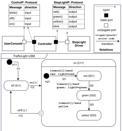
TrafficLight USM on (C11) Controller StopLight Driver UserConsole Message Direction red() output green() output yellow() output blink output Message direction blink() input off() input on() input trigger[guard]/ action code transition base port conjugate port Notations typed t11 t12 off (S11) red (S21) green (S22) yellow (S23) t21 t13 in11 in21 on[]/ off[]/ t23 t22 timeout[]/send red; lightV=red timeout[]/send green; lightV=green timeout[]/send yellow
ControlP: Protocol StopLightP: Protocol
Fig. 1: Model of a traffic light in UML-RT
Definition 6 (Assumptions concerning well-formedness and execu-tion semantics of USMs)
Following [27, 46, 69], we make the following assumptions concerning the well-formedness and execution of USM s:
– Only transitions that start from a choice-point can have a guard, and no transition that starts from a pseudo-state can have a trigger.
– There are no orthogonal regions (i.e., a USM cannot be in two basic states at the same time), and there is no support for the UML concepts fork, join, shallow history, and final states.
– States do not have idle (do) actions.
– There is no notation for history. Instead, any transition to a composite state is assumed to end in an implicit history state inside the composite state (i.e., when returning to a previously activated composite state, the execution of the sub-state machine will resume from its last active state).
– Triggers of transitions starting from the same basic or composite state must be disjoint, i.e., ∀ t1, t2 ∈ T : t1.src = t2.src ∧ t1.src 6∈ Sp =⇒ t1.trig ∩ t2.trig = ∅.
Note that these rules are also enforced by existing UML-RT tools and none of them has been defined specifically for this study. Still, our approach can be extended to support AND-states and other concepts not offered in UML-RT.
2.2 Running Example
We use the control system of a simple traffic light as a running example. The top-level structure of the system is shown in Figure 1 which consists of three capsules: UserConsole (UC), Controller (CTR), and StopLightDriver (SLD). CTR is connected to UC and SLD using two base ports, which are typed by protocols ControlP and StopLightP accordingly. The UC capsule collects user input, which it passes on to the CTR capsule, the capsule controlling the light. CTR sends the control actions as messages to the SLD which transfers these messages through a hardware port to the traffic light. The behaviour of CTR is shown in the USM TrafficLight in the Fig. 1 which is intentionally left incomplete to demonstrate live modeling features. Note that variable lightV is used to save the current color of the light.
2.3 Live Modeling
Model execution is a key enabler for the performance of validation and verifi-cation (V&V) activities of complex system behaviors. For instance interactive debugging, testing, model checking, and trace analysis are some of the V&V techniques that have proven useful to analyze the behavior of complex systems based on executable models.
However, with the way model execution infrastructures and V&V tools for executable models are currently built, the development process for executable models is very rigid, requiring the modeler to re-start an execution or anal-ysis whenever the need for changes on the model arises. In particular, in the current practice, domain engineers are forced to follow a fixed process for ex-ploring changes on their executable models: First update the model, then run the execution that consists of several steps depending on the execution mech-anism (interpretation or code generation), examine and analyze the observed behavior, stop the execution and return to updating the model. This edit-execute-edit cycle significantly limits the agility of the development process of executable models and thus also developer productivity.
Live modeling can free modellers from the edit-execute-edit cycle by pro-viding continuous, real-time, and interactive feedback to modelers about the impact of their changes on the execution of a model. As a result, it becomes much easier for modellers to explore the design space of the system they are
developing. This not only eases the development of complex software-intensive systems, but also facilitates learning modeling languages and has the potential to improve the quality and efficiency of the development process [85, 90].
Similar to live programming, there is no single approach to realizing live modeling as the applicable techniques depend on the type of modeling lan-guage and its execution mechanism. While the main goal of the live modeling always is to shorten the edit-execute-edit cycle and provide the developer with more immediate feedback on the changes, the way this goal is achieved can differ greatly. Below we collect some of the main criteria that can be used to distinguish and classify live modeling. The criteria capture user-level capabil-ity differences, but also implementation-level technical differences. Concepts and examples from live programming are used for illustration due to the higher degree of maturity of live programming.
1. Responsiveness. This criterion concerns how quickly and readily feed-back is provided to the user in response to changes in the model. With the highest degree of responsiveness (live, instantaneous feedback) the effect of a change is reflected immediately and without the need for user interven-tion. Domains that offer tools with a very high degree of responsiveness include live music production, visual signal processing, or graphical user in-terfaces. Examples of languages used include Viva [81], Max Language [72], and Vivide [80]. The supporting language infrastructures maintain a map-ping between program elements and their views and provide live feedback through rapid, continuous data flow between the elements and their views. Supporting such a mapping and the data flow is not possible in many domains and languages, including many modern general purpose program-ming languages including imperative languages such as Java. Apart from live feedback, two other techniques can be used to get timely, yet slightly less responsive, feedback: (a) Read-eval-print loop (REPL): A REPL pro-cesses user inputs (e.g., a single expression or statement), evaluate or ex-ecute it, and display the result. A REPL is intended for quick feedback, and its scope is often only limited to simple expressions or statements. (b) Fix-and-continue: This technique, supported by many modern IDEs, allows code to be changed while the program is executing. However, the execution is updated upon user request. Often, this update requires paus-ing the program execution before the update and resumpaus-ing the execution after the update.
2. State transfer. This criterion concerns how the relevant aspects of the current execution state of the running program (data segment) are mi-grated after the execution (code segment) has been updated. There are two main techniques for state transfer: (a) Real time: This technique keeps the current state of the program intact and allows the changes to only affect the next execution steps (e.g., [35]). This mechanism is often used in environments that support fix-and-continue. In some domains in which certain code blocks in the program are executed continuously (e.g., visual programming) or the past executions are not important (e.g., music
perfor-mance), this method can work well. However, it has several problems and does not deal well with, e.g., changes that are applied to instructions that have already been executed [56]. (b) Re-execution: This technique recreates the execution state by replaying the execution traces while changes are be-ing taken into account (e.g., [23]). This technique is an expensive approach and introduces extra complexities and can delay immediate feedback. 3. Execution mechanism. Models can be executed by interpretation or
code generation. With interpretation, live modeling features and mecha-nisms can be freely selected and implemented depending on the modeling language. However, with code generation, the support for live modeling is limited based on the services provided by the target language, i.e., the programming language that the generated code is in. Also, in the context of code generation, extra challenges are imposed due to the need for bi-directional mapping of the concepts of the modeling language to concepts of the target language.
4. Supported operations and their scope. This criterion targets the edit operations supported (e.g., add/remove/update) and their scope. For in-stance, most of the IDEs for imperative programming languages only al-low updates of method bodies. The addition of new methods or changes to the signature of a method are not allowed. Often, the reasons of these limitations are technical, implementation-level challenges, or the desire to improve performance or simplify the implementation.
5. Integration with debuggers. How a program executes is often not ap-parent from its output. This is particularly true for complex systems. Live programming only updates certain views of the program execution, which may or may not support one of the most important development activities sufficiently well: debugging. Thus, even in the presence of live modeling, there likely still is a need to use debugging services such as tracing, re-playing and stepping through executions to be able to locate and correct bugs. This is particularly important when the execution does not produce appropriate output. As a result, many live programming (e.g., [59]) ap-proaches integrate live programming services with debugging facilities to provide effective debugging support.
2.4 Scope of our work
In terms of these criteria, the focus of our work is to develop support for live modeling in the context of state machine models that are executed using code generation, more specifically live modeling using UML-RT models when they are executed by generation of C++ code. We aim to propose a solution that supports fix-and-continue, real time state transfer, and integration with debugging services to provide REPL capability. Integrating real time state transfer with debugging support is challenging. Suppose, e.g., that the action of transition t23 is changed when the execution of the traffic light is in state yellow. In that situation, there is no way for users to ever see the effect of the
Element Add Remove Update
Capsule No No No
Port No No No
Protocol No No No
Variable Yes No No
State Yes Yes Yes
Transition Yes Yes Yes
Action Yes Yes No
Trigger Yes Yes Yes
Guard Yes Yes No
Table 1: Supported Edit Operations
change. To deal with this challenge, we also provide a limited type of execution replay which will be discussed in Section 4.
In theory, every element of the model can be edited (update/add/delete) during a live modeling session. However, as shown in Table 1, our work only focuses on changing state machines. Changes to, e.g., the structure (by, e.g., adding or removing a port or capsule) except for adding variables are not supported. Removing or editing a variable without restarting the execution requires a complex memory manipulation of the running model that can lead to subtle errors. In addition, we only support basic addition and removal op-erations involving statements to send messages and arithmetic and logical expressions. Note that there is no fundamental limitation to extending the support for addition and removal and can be achieved in the context of our prototype. Currently supported actions are sufficient to show the applicability of our approach.
Some of the possible live modeling operations on the USM TrafficLight include OP1: add actions to transition t23 which lacks an update of variable lightV, OP2: add a transition along with actions and a trigger from state yel-low to state red, and OP3: remove state yelyel-low when it is the active execution state.
2.5 Live modeling by leveraging live programming (initial experiment) Figure 2 shows the process for realizing live modeling using services offered by the target language of the code generation. We have implemented the process in the context of Papyrus-RT and generated C++ code to provide a fair and realistic assessment of the existing approach. The bold arrows show the steps required for the application of changes to a model while it is running. We assume that changes are applied to model M1 which result in model M2. The model-level changes (i.e., Diff(M1,M2)) are translated into code using incre-mental code generation, then resulting code is compiled and shared libraries are built using code-based build tools (i.e., gcc and Make). Then the running program, generated from model M1, is updated to refer to the shared libraries without restarting the execution which is achieved by generating the code that
Code Generation
Edit operations M1
Incremental Code Generation M2 Code (C++) Run Program (Executable) Compile & Build
Code (C++) Incremental Build & Compile
Program code (B1) Program state (S1) Hot-Swap Shared Libraries (Patch) Program code (B2) Program state (S1) Running Program Updated Running Program
Fig. 2: Existing approach for live modeling by leveraging live programming services offered in the context of the target language
can detect changes to shared libraries and load/unload them at runtime. Note that this process is almost the same for compiled languages (e.g., C, C++, Java), while for scripting languages a much simpler process, without the re-quirement to compile and build, can be used. Usually, in the context of RTE systems, the target language of the generated code is a compiled language.
In addition to the complexity of the incremental code generation which often is not supported properly by existing MDD tools, we review and illustrate (in the context of the running example) the most significant challenges in the above solution:
– Edit Latency. The process for applying a change on a running model (i.e., incremental code generation and build, and hot swapping) is time-consuming, and our experiment shows that, on average, the process takes more than half a second for each change. This can greatly degrade user experience [55, 56] and prevents immediate feedback.
– State transfer. No state transfer mechanism is supported by default in the context of C++.
– Debugging support. In some application domains in which program ex-ecution produces continuous and observable outputs, the live update can be enough for live programming/modeling. However, in the context of live modeling, where the model execution may perform computation without
Original Model (M1) Instrumented Model Self-reflective Program Live Modeling Plugin Model Instrumentation Code
Generation compile build
link
Self-Reflective Code
Fig. 3: Generation of a self-reflective program
observable outputs, the application of changes without the ability to ob-serve their effect does not appear to be useful. Thus, similar to popular IDEs (e.g., Java, Eclipse, Visual C#/C++) that mix live programming with debugging, we need to provide a meaningful, effective integration with debugging to provide live feedback. This is not supported by default and requires extra efforts. Consider, e.g., changes to the way variable lightV is updated (OP1, and OP2 ). Without debugging support it is not possible to verify whether the not directly observable effects of these changes are as expected.
3 Approach
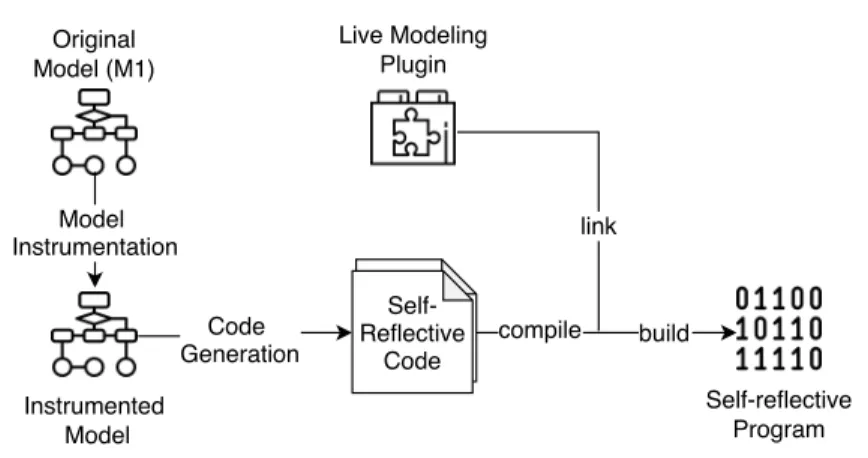
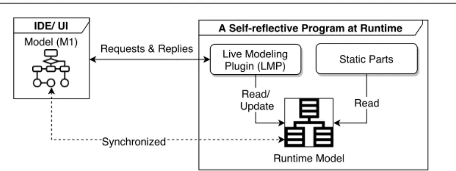
As discussed in Section 2.5, the use of services offered in the context of live programming to implement live modeling imposes several challenges and re-strictions. To overcome these, we propose an approach for live modeling inde-pendent of live programming services in the context of state machine models when they are executed by code generation. The approach consists of two phases: Generation of a self-reflective program and live modeling using the self-reflective program. As shown in Fig. 3, first, code generation and model transformation techniques are used to automatically create a program (a self-reflective program) that embeds all required services for live modeling and debugging along with an interface for using them. Second, live modeling ser-vices are directly provided via interaction with the self-reflective program as shown in Fig. 4. This decreases the edit latency significantly since there is no need for code generation, compile & build, and hot-swapping for each edit. Also, model debugging services provide an infrastructure for REPLs. In the following, we provide an overview of each phase.
A Self-reflective Program at Runtime
Requests & Replies Live Modeling
Plugin (LMP) Static Parts
Runtime Model Read/ Update Read IDE/ UI Model (M1) Synchronized
Fig. 4: Live modeling using self-reflective program
3.1 Generation of a Self-reflective Program
Fig. 3 shows the three steps for the generation of a self-reflective program ca-pable of supporting live modeling:
Model instrumentation. In this step the model is instrumented automati-cally using model-to-model transformation to provide debugging services mainly for (a) variable view/changes that are required for the read-eval-print loop (REPL), (b) producing execution traces to support execution replay, and (c) adding a mechanism for pausing the execution of the model when users want to apply model changes to the execution or use the REPL. As discussed, our approach supports fix-and-continue in which the execution is updated upon user requests by pausing the program execution and resuming the execution after the update.
Code generation. The main purpose of this step is to generate a self-reflective program that allows the live update of the model elements during the execu-tion. Similar to programming languages, the execution semantics of models is defined based on their Abstract Syntax Tree (AST). Thus, to allow model updates during the execution: (a) the AST of the model (i.e., model elements which are to be modifiable) should be explicitly embedded/defined in the gen-erated code, (b) whenever it is required, the execution should progress using the compiled version of the embedded AST rather than the statically gener-ated code, and (c) the embedded AST should be modifiable during execution. The complexity of this step is language-dependent. The conciseness of the ab-stract syntax and semantics of UML-RT simplified the implementation of our prototype.
Compile, link, and build. Existing code-based tools are used to compile and build the generated code and create the self-reflective program. Also, a live modeling plugin that provides an interface for using live modeling and REPL services is linked to the generated program in this step. Implementing the interface as a separate plugin allows the separation of concerns. The plu-gin imposes minimum overhead since it only needs to be loaded when the live modeling service is used.
3.2 Live modeling using the self-reflective program
Figure 4 shows an overview of how live modeling is supported via interaction with the self-reflective program. During live modeling, a change in the design model is translated to a live modeling command and sent to the live modeling plugin (LMP ) which is loaded as part of the self-reflective program. The LMP processes the request and updates the corresponding elements in the runtime model so that the design and runtime models are kept synchronized. The static parts in the self-reflective program correspond to the generated code of the model that mainly controls the execution based on the runtime model and provides support for the self-reflection services. By separating the runtime model that captures the editable part of the model from the static part that is compiled, the self-reflective program can benefit from the best of both worlds: better performance for the static part due to compilation on the one hand, and increased flexibility and support for runtime change via interpretation on the other hand.
Also, LMP provides an interface for the REPL, which can be used to evaluate or execute simple expressions or statements to, e.g., inspect or modify the values of variables.
3.3 Generality of our approach
The approach proposed above can be applied in the context of different mod-eling languages to realize live modmod-eling and debugging if the language has the following properties:
– Deterministic execution. Without deterministic semantics, some of the live modeling services such as execution replay cannot be realized properly. – Essential constructs. The language should support required constructs to
allow the implementation of self-reflection, interaction with external ap-plications (e.g., message passing), and control flow (e.g., choice-points) to add debugging services into models by instrumentation (e.g., pause and resuming the execution).
Since the execution of models is a language-dependent concept, there is no way to provide a generic implementation of the framework using existing techniques and tools. However, still, the communication, self-reflection, and tracing can be implemented similarly. Also, our model transformation imple-mentation can be ported to other state machine languages (e.g., UML state machines). Additionally, our live modeling plugin can be adapted to other modeling languages for which code generation to C/C++ is available.
4 Live Modeling of UML-RT Models
In this section, we discuss the application of our approach to live modeling in the context of UML-RT models and demonstrate a tool that illustrates it.
Original Structure Transformed Structure CapsuleB CapsuleA typed dbgAgent CapsuleB CapsuleA protocol1 message1 ... typed dbgProtocol dbgMsg() typed protocol1 message1 ... transformed to
(a) Step1: instrumentation of the structural model Original USM Instrumented USM
C1 States and transitions are not shown C1
States and transitions are not shown
S1 S1 dbgMsg[]/LMP(context) dbgMsg[]/LMP(conext) [nextS==S1]/ if (replayFlag) replay() [nextS child(C1)]/ transformed to
(b) Step2: instrumentation of the USM’s root
C1 C1
S11 S11
C11 States and transitions are not shown
[nextS==S11]/ if (replayFlag) replay() [nextS child(C11)]/ transformed to C11 States and transitions are not shown
(c) Step3: instrumentation of composite states
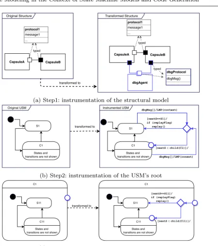
Fig. 5: Demonstration of UML-RT model instrumentation by examples. The added elements are colored blue (child(C1) returns states inside C1).
4.1 Instrumentation of UML-RT models
We adapt the model debugging services, including variable view and message injection proposed in MDebugger [5, 7] to implement the REPL. Also, we apply model instrumentation in four steps (the first three steps are shown in Figure 5) to equip the model with the capabilities required for supporting live modeling. In the following, we discuss the rationale behind each step and the capabilities it provides.
1. Instrumentation of the structural model. As shown in Figure 5a, the first step of the instrumentation adds capsule dbgAgent and protocol dbgProtocol to the structural model, both of which have been adapted from MDebugger. Then, a port is added to each capsule that is typed with protocol dbgPro-tocol and connected to the dbgAgent capsule. Capsule dbgAgent acts as a
gateway between external applications (e.g., a live modeling environment) and the capsules. It accepts external messages through TCP or shared memory and passes them to the relevant capsules [7]. This step allows the injecting of the dbgMsg message by communicating with capsule dbgAgent to pause the normal execution (execution of the user-defined part of the USM) of the capsule and start a live modeling session in which the model execution can be updated and the REPL service can be used.
2. Instrumentation of the root of the USM. Steps 2 and 3 instrument the USM such that (1) its normal execution is paused and a live modeling session is started upon injection of the dbgMsg message, (2) the normal execution is continued in an appropriate execution state when the live modeling session is finished.
Figure 5b shows how a the root of an USM is instrumented in Step 2. First, a choice point state (ch) is added to the root. Second, transitions are added from all basic and composite states in the root to ch whose triggers are set to dbgMsg. Thus, the added transitions are taken upon reception of dbgMsg. The actions of the transitions are set to LMP(context) which is a function that starts the live modeling session and is a part of the live modeling plugin. The function returns the next execution state (nextS ) and thus specifies where the execution needs to be steered from the ch. Also, argument context of LMP is used to pass the relevant information to the plugin, more importantly, the current active state and a callback address that is used by the plugin to call self-reflection functions of the capsule such as add or remove state.
Third, entry-points are added to all composite states inside the root. Then, transitions are added from ch to all basic states and these entry-points. The guard of the transitions that end at a basic state is set to a boolean expression that checks if the basic state is the same as nextS. The guard of transitions that end at entry-points is set to check that nextS is one of the states directly contained in the composite state being entered. Also, the action of the transitions to the basic states calls function replay if replayFlag is set. Function replay is discussed in detail in Sec. 4.3. By default, the execution of the capsule returns to the last active state (i.e., nextS is set to the most recently active state) before the live update (i.e., fix and continue), but the user can select other basic states for nextS. In that case, the live modeling plugin replays the execution based on the most recent execution traces of the basic state until the execution reaches the last state before the update or a state which has not been visited before (i.e., no execution trace is available for it).
Note that the handling of messages in UML-RT (as in many other state machine languages) is subject to the run-to-completion semantics, i.e., the processing of an incoming message will not start until the processing of the previous message has completed. Since that dbgMsg is a regular UML-RT message, it also is subject to run-to-completion. This means that the acti-vation of a live modeling session is consistent with the UML-RT semantics. It also means that all messages sent by other capsules during the
execu-tion of a live modeling session are queued. Thus, the normal execuexecu-tion of the capsule is paused correctly during the live modeling session, and no message is lost.
3. Instrumentation of composite state. Figure 5c shows how a composite state is instrumented in Step 3. First, a choice-point (ch) is added into the com-posite state. Then a transition from the entry point (added in Step 2) to ch is added. Then, for all basic states and entry points that have been added to the composite state, transitions are added from ch to these states and points. The guards and actions of the transitions are set as in Step 2. This instrumentation allows the execution of the capsule to be steered to any of the states inside the composite state when the live modeling session is complete. This capability is essential to steer the execution into a desirable state when the active execution state has been removed during the live modeling session.
4. Instrumentation of basic states. In the last step, the exit actions of basic states are instrumented to ensure the generation of appropriate trace infor-mation before the state is exited. An execution trace is defined as a tuple hstate, lastM, varsi where state ∈ Sbrefers to the state being exited, lastM refers to the message that caused the state to be exited, and vars is a map recording the values of variables right before the state was exited. This information allows replaying the execution from a state based on the last time the state was visited. Also, the exit actions of states are guarded to ensure that no exit action is executed when a transition from a basic state is taken due to the reception of dbgMsg (i.e., when live modeling plugin is activated).
Note that the instrumentation of the model is applied before the code gen-eration. The instrumentation also needs to be updated as the model is changed during live modeling to keep the runtime model consistent, and allows the han-dling of dbgMsg, which is required for starting LMP. Thus, the instrumentation is updated accordingly, based on the type of each change (ref. Sec. 4.3.3). The update of the instrumentation at runtime is achieved by updating the runtime model rather than the design model.
Figure 6 shows the result of the instrumentation of the USM TrafficLight. As shown, the execution in any of the basic states is paused and the live mod-eling is started by calling LMP(context) as action of t14 or t16 upon receiving the dbgMsg. Also, the execution can move to any basic state (possibly through one or more choice-point states that have been added during instrumentation.
4.2 Generation of the Self-reflective Program
As discussed in Sec. 2, the syntax for behavioural specification in UML-RT is concise and consists mainly of states, transitions, variables, and actions. In order to embed these elements in the generated code while still allowing for their modification at runtime, a runtime model is used. In what follows, we
Instrumented TrafficLight USM on (C11) t11 t12 [nextS==S11]/ if (replayFlag) replay() t13 off (S11) t16 dbgMsg[]/LMP(context) red (S21) green (S22) yellow (S23) t21 in11 t13 in21 on[]/ off[]/ t23 t22 timeout[]/send red; lightV=red timeout[]/send green; lightV=green timeout[]/send yellow dbgMsg[]/ LMP(context) t14 t15 ch1 t24 t27 t26 t25 ch2 ex1 en1 [nextS {S21,S22,S23}]/
Fig. 6: Instrumented USM stoplight for state transfer and safe update (added elements are shown using dashed lines and to make the diagram more readable, only four of the outgoing and incoming transitions are labeled with a guard and trigger (t13, t14, t15, t16)). in11 off on ch1 en1 ex1 red green yellow null ch2 in21 null {t11} on() {t12} dbgMsg() {t14} null {t13,t15} dbgMsg {t16} null {t24} null {t13} timeout() {t22} null {t25,t26,t27} null {t21}
State Table Trigger Tables
timeout() {t23}
effect, guard entry, exit triggers 0..* State name: string UMLRTHashMap:triggerTable ActionCode functionPtr: void* Transition name:string Trigger port : UMLRTPort signal: UMLRTInSignal name:string from, to
Fig. 8: Class diagram of extended classes to RTS
first describe the runtime model and then discuss how the code for the runtime model of UML-RT model is generated.
State and trigger tables. Let us define a state table of an USM as a map from its states to references to trigger tables where a trigger table is a map from a trigger to a non-empty set of transitions. A null reference is used when a state has no outgoing transitions. A trigger table records the outgoing transitions from a state along with their trigger. A null trigger is used when a transition has no trigger. Figure 7 shows how the instrumented stoplight model in Figure 6 is translated to a state and a trigger map. At runtime, a state s is represented as references to the entry and exit actions (e.g., a function pointer in C++), the parent of s, and the children of s (if any), as shown on the left of Figure 7. Similarly, for each transition, references to its source and target states, guard, and action are kept.
Runtime model. A runtime model of a system is a set of tuples hc ∈ C, sm, Nvars, Nacts, Eti where c refers to a capsule, sm refers to the state table of the capsule’s USM, TM refers to the set of trigger tables that are referenced from sm, Nvars is a map of newly added variables, Nacts refers to the newly added or modified actions of the capsule’s USM, and Et is a map from basic states to the most recent execution trace generated before exiting the state. The generated program initializes the runtime model for the system at the beginning of the execution which is then used to support live update and feedback. Note that at the beginning of the execution the actions and guards of transitions refer to functions of the compiled code.
Generation of runtime model. We extend the code generation of RT [68] to generate the self-reflective program. The code generation of Papyrus-RT relies on a service library that provides basic functionalities such as com-munication, and base classes for capsules and protocols. Our extension for the generation of the self-reflective program is two-fold: First, we extend the
Listing 1: An excerpt of the code generated code for creation of rumtime model of the running example
{
addState( new UMLRTCapsule::UMLRTState( "off" ) );
addState( new UMLRTCapsule::UMLRTState( "on::red" )); // add state red inside a composite state on
//.. omitted
addTransition( getState( "off" ), new UMLRTCapsule::UMLRTTrigger( "controlPort", "turnOn" ), new UMLRTCapsule::UMLRTTransition( "off__on", getState( "off" ), ... );
//... omitted
}
service library with a set of C++ classes and add functions (C++ methods) into the base class of the capsule to provide support for self-reflection and interaction with the live modeling plugin. E.g., function addState is added that supports addition of a state into the capsule’s USM. Second, we change the code generation related to the capsule to generate methods that initialize the runtime model through the creation of appropriate states and transitions which are also added to the state and trigger tables.
Figure 8 shows the high-level class diagram of the C++ classes that are extended in the service library. As shown, for each design concept (e.g., state, and transition), a corresponding class is defined that captures not only the runtime information but also the properties that are required to capture their design properties (e.g., state names). Also, the class ActionCode is used to capture the actions and guards with the help of a function pointer. It is im-portant to note that the function pointer refers to the compiled action code at the beginning of the execution, but when the action is updated at runtime during live modeling, it refers to a function proxy that is loaded as part of the live modeling plugin. The function proxy receives and interprets actions. By relying on this extension, we adapt the code generator to generate method calls for initialization of the runtime model. An excerpt of methods calls for the stoplight example is shown in Figure 1.
The explanation above provides a brief overview of the code generation process without dwelling into the technical detail. In addition, in this work, we advocate the idea of the generation of the self-reflective program. We in-tentionally do not constrain the code generation any further, because different solutions can be applied depending on the context of the modeling language and environment. Nevertheless, interested readers can find the source code of our implementation in [4].
live modelling session Processing of a single command A capsule Live modeling plugin dbgAgent Live modelling environment
start live modeling session
send dbgMsg LMP(context)
establish a TCP connection
send a command (e.g., add state)
call related function
return return the result of command
process command
resume the execution or replay
select the next state, or a path
call replay or resume function
return end the TCP connection
Fig. 9: The flow of live modelling via interaction with the self-reflective pro-gram
4.3 Supporting Live Modeling for UML-RT Using the Self-reflective Program Figure 9 shows the flow of live modeling via interaction with the self-reflective program. The flow consists of the following three steps.
1. Start a live modeling session. An external application (e.g., live mod-eling environment) can update the execution of a capsule. To do that, first, a live modeling session needs to be started by sending a certain message to the dbgAgent. The message specifies the name of a capsule whose ex-ecution needs to be updated. dbgAgent processes the message and sends a dbgMsg to the capsule. As discussed in Sec. 4.1, reception of a dbgMsg triggers a transition in the capsule’s USM that activates LMP by calling function LMP(context). When the LMP is activated, it establishes a TCP connection with the external application, through which the live modeling services can be used by sending relevant messages.
2. Updating the execution and using REPL. When the live modeling session is established, the external application can use the live modeling services or REPL by sending relevant messages to LMP through the TCP connection. When LMP receives a message, it processes the message and
calls the relevant functions (the functions that are extended into the base class of the capsule) using the callback address that is passed to the LPM during its activation. Finally, LMP returns the result to the external ap-plication. Note that we assume the external application validates the user request (e.g., make sure the syntax of added action is valid, or the action does not make the model inconsistent) before sending the request to LMP. 3. Resuming the execution of the capsule. During the live modeling session, the normal execution (execution of user-defined parts) of a capsule is stopped and the LMP is activated. Thus, after finishing the update, the normal execution of the capsule needs to be resumed. This can be done either by using the replay function or simply resuming the execution. By resuming the execution, the LMP tries to select the next execution state (which, typically, would be the most recently active execution state). In case if the most recently active execution state has been removed during the live modeling session, LMP communicates with the external application to select the next execution state. The external application can select the next state via interaction with the user (our prototype supports this) or apply heuristics and other techniques to select the next execution state (e.g., [85]). We argue that the selection of the next state via communication with the user is simpler and better than other possible solutions since, during the development, it is reasonable to assume that the user is familiar with the model and can select a suitable state. Note that the user may have removed all states during the live modeling session. In that case, the execution cannot be resumed, and the user needs to define new states to resume the execution. After resuming the execution, the live modeling session is terminated. The details of the replay function will be discussed later in this section.
As discussed in Sec. 4.2, functions are added into the base class of the capsule to enable self-reflection. The added functions support the full range of live modeling services, including replaying execution, adding/removing/up-dating states, transitions, actions, and triggers. Variables can be added, in-spected, and updated, but not removed. The implementation of most func-tions is straight-forward as they are implemented by adding, modifying, or removing entries in the runtime model. In the following, we first discuss how execution replay and the modification of actions are implemented. Then, we explain the other services by example. Finally, we discuss how OP1-3 (see 2.4) can be addressed in the context of running example.
4.3.1 Execution replay (re-execution)
We support real-time state transfer (ref. 2.4), which causes issues when the changes in model include an instruction that has already been executed, be-cause users cannot see the effect of their changes. Suppose, e.g., the action of transition t23 is changed when the execution of the traffic light is in state
Algorithm 1: Replay execution
Input : Source state (fromState), Destination state (toState)
1 Let requiredMsg and replayedState be an empty sequence 2 replay(f romState, toState, requiredM sg, replayedState)
3 Function replay(State: fromState, toState, Sequence: requiredMsg, replayedState )
4 if (fromState=toState) then
5 trace ← lastT (replayedState[0] ) // get the most recent execution trace of replayedState[0]
6 reset (trace.vars) // reset variable values to values extracted from trace (trace.vars)
7 Set the current execution state to replayedState[0]
8 defer all messages in the capsule queue
9 inject (requiredMsg); // inject all messages required to replay using debugging command
10 return // replay complete
11 else
12 Let trace be the most recent execution trace of fromState 13 if (trace=null or replayedState.contains(fromState)) then
// error, there is no path to toState
14 else
15 requiredMsg.append (trace.lastM )
16 replayedState.append (fromState)
17 nextS ← lookupStateMap(fromState,trace.lastM ) // find the next
state using the state maps
18 replay(nextS,toState,requiredMsg,replayedState);
yellow. In that situation, there is no way for users to ever see the effect of the change. To deal with this challenge, we provide a limited type of execution re-play that allows execution the USM based only on the most recently processed message at each state.
Algorithm 1 shows how the execution replay is implemented. The algorithm accepts states fromState (source state) and toState (destination state) as input. It first creates two empty sequences requiredMsg and replayedState and calls the function replay. Function replay is a recursive function that tries to find an execution path (a sequence of transitions) from fromState to toState such that the sequence requiredMsg causes that path to be taken (i.e., requiredMsg contains exactly the messages needed to trigger the transitions on the path). The code of function replay is shown in Algorithm 1. Its execution branches based on whether or not the source fromState and toState are equal:
– (fromState is equal to toState). A path has been found. In this case, the variable values are reset using the most recent execution trace of the source state, and all required messages are injected to replay the execution to the destination state. Before injecting the required messages, all existing mes-sages in the capsule queue are deferred to ensure the replaying will not be interrupted. The users can recall these messages after the replaying is com-plete by adding actions or a debugging command. The message injection is supported by calling a function that has been added into the capsule base
class (see Section 4.2). The function adds the relevant UML-RT message into the queue of the capsule.
– (fromState is not equal to toState). A path has not been found yet. In this case, the function raises an error if: (1) fromState has not previously been visited by checking its most recent execution trace, since the reexecution of a path cannot be performed without a trace for each state in the path, or (2) there is a loop in the path. This means a path from the source state to the destination state cannot be found based on the most recent execu-tion traces. If no error is raised, the funcexecu-tion adds fromState and its last processed message (lastM ) to replayedState and requiredMsg respectively and calls function replay recursively by using nextS as the next state in the path.
Note that the offered replay mechanism is mainly useful during debugging, specifically step-wise debugging, where a bug in a specific part of the model needs to be localized and fixed. In this situation, the replay function allows users to rewind (reset) the execution to a specific state and then see the effect of any changes to the part without having to restart the application. But since the replay function only replays the most recent traces, the rewind capability is limited in the number of steps it supports, especially when the state ma-chine contains cycles. Also, the replay mechanism only focuses on replaying the execution of one capsule (target capsule) by injecting the required mes-sages on behalf of the other capsule. During the replay, the target capsule can send/receive messages to/from other capsules that may not be expected. Thus, the capsules may not react as expected. However, this does not cause an issue for the re-execution of the target capsule since we inject all required messages. To deal with this issue, it is possible to extend the replay function to rewind the execution of the relevant capsules as well as the target capsule to allow the execution of the whole system to be replayed without the injection of messages. We left this for future work.
4.3.2 Editing actions
As discussed in Section 2, actions can be provided in the form of the effect of a transition, or as the entry or exit code of a state. Papyrus-RT allows actions to be written in C++. During code generation, a C++ function is generated for each action with a body that contains the action as given in the model (i.e., no translation is performed). Thus, the editing of actions at runtime would require using the live modeling support provided by C++. However, as discussed in Section 2 this support is limited. To overcome this issue, our method to support the editing of actions is two-fold, as discussed in the following.
– Code generation. As discussed, each transition and state in the runtime model has function pointers for actions. During the code generation, the function pointers are initialized to refer to the functions that are generated by the default code generation of Papyrus-RT. Thus, at the beginning of
in11 off on ch1 en1 ex1 red green yellow null ch2 in21 null {t11} on() {t12} dbgMsg() {t14} null {t13,t15} dbgMsg {t16} null {t24} null {t13} timeout() {t22} null {t25,t26,t27} null {t21}
State Table Trigger Tables
timeout() {t23} in11 off on ch1 en1 ex1 red green null yellow null ch2 in21 null {t11} null {t12} dbgMsg() {t14} null {t13,t15} dbgMsg {t16} null {t24} null {t13} null {t25,t26,t27} null {t21}
State Table Trigger Tables
timeout() {t23} (2) remove state red
(3) remove transition t23 (1) remove trigger of t12 timeout() {t22} (1) (2) (2) (3) (3)
(a) Remove state, transition, and trigger (actions and corresponding removed elements an-notated using the same number. )
in11 off on ch1 en1 ex1 red green yellow null ch2 in21 null {t11} on() {t12} dbgMsg() {14} null {t13,t15} dbgMsg {t16} null {t24} null {t13} timeout() {t22} null {t25,t26,t27} null {t21}
State Table Trigger Tables
timeout() {t23}
(3) update trigger t28 to to timeout()
(1) add state blink inside state on
(2) add transition t28 from blink to green
in11 off on ch1 en1 ex1 red green yellow null ch2 in21 blink S12 null {t11} on() {t12} dbgMsg() {14} null {t13,t15,t31} dbgMsg {t16} null {t24} null {t13} timeout() {t22} null {t25,t26,t27,t29} null {t21}
State Table Trigger Tables
timeout() {t23} timeout() {t28} (1) (1) (2) (3) (4) add state s1 to the root of USM
dbgMsg {t30}
(4) (4)
(4)
(b) Add state, transition, and trigger (actions and corresponding added elements annotated using the same number.)
Fig. 10: Examples of live modeling services that are provided by updating the runtime model.
the execution, all the actions are executed as binary code (generated by C++ compiler), and no performance overhead is introduced.
– Edit at runtime. To update an action at runtime, we update the relevant function pointer in the runtime model to refer to a proxy function that interprets the updated action. This means that as soon as an action is updated, it is no longer executed as binary code until the end of the execu-tion. Note that an action is only interpreted when it is edited, and each of the actions is treated separately (editing of one action does not affect other actions). Also, in our current implementation, the interpretation support is limited to arithmetic expression, sending messages, and logical expressions. We left the extension of the interpreter as future work.
4.3.3 Other live modeling services
Figure 10 shows some examples of how adding/removing/updating states, transitions, and triggers is supported by updating the runtime model, in the context of the stoplight example. Note that by adding/removing states, the instrumentation is updated. By adding state blink inside state on, a transi-tion from blink to ch2 is added. Similarly, by adding state S12, transitransi-tions are added from/to S12 to/from ch1. As discussed in 4.1, the added transitions allow the start of a live modeling session upon injection of the dbgMsg and the steering of the execution to an appropriate state, when the live modeling session is finished.
4.4 Live Update Operations on the Running Example
We review how the five operations in Section 2.1 can be performed based on the provided services:
– OP1. (add actions to transition t23) The action of transition t23 can be modified. If the execution is past transition t23, the execution can be replayed from state green to state yellow. In state green, REPL commands can be used to inspect the effect of the modified action.
– OP2. (add a transition along with actions and a trigger from state yellow to state red) OP2 can be addressed by using add transition and add action services. Note that the trigger can be specified when adding transition.
– OP3. (remove state yellow when it is the active execution state.) The user can remove state by activation of the live modeling session, when the execution is in state yellow. During the resuming of the execution, the user is asked to select the next execution state, which can be any of the other basic states. Then the execution can be steered to the selected state possibility through choice-point states that are added during instrumenta-tion.
4.5 Tool Support (Live-UMLRT)
This section presents Live-UMLRT [8], a tool that supports live modeling of UML-RT models and embodies our approach.
4.5.1 Implementation
To develop Live-UMLRT, we used Papyrus-RT as the primary tool to model RTE systems, the Papyrus-RT code generation extension to generate self-reflective code, and the Epsilon Object Language (EOL) [52] to implement the transformation rules required for refining the models into instrumented models. The LMP is implemented using C++, ANTLR [64], and the Boost
1 USM view
2 DBG view
Fig. 11: User interface of Live-UMLRT.
C++ Library [10]. REPL commands are implemented using debugging fea-tures that are ported from MDebugger [7].
4.5.2 Live-UMLRT Features
In the following, we discuss the features of Live-UMLRT1 from the user point of view. When it is possible, the use of features is explained using the running example.
Setup and run: The Live-UMLRT is integrated into Papyrus-RT as an Eclipse plugin and can be downloaded and installed from the Live-UMLRT repository2. After installation, it can be used to edit UML-RT models at run-time simply by defining a run configuration (i.e., Eclipse run configuration) inside Papyrus-RT. When a model is executed using the defined configuration, the model instrumentation, code generation, and build are executed automat-ically in the background without distracting end user. The UI of Live-UMLRT is shown in Figure 11 which is split in two parts, a USM view ( 1 ) and a DBG console ( 2 ). In the USM view, the user can view and edit the USM of the capsules. In the DBG console the user can issue REPL commands to investigate and change the model at runtime. Basic REPL commands (e.g.,
1A demonstration video: https://www.youtube.com/watch?v=6GrR-Y9je7Y 2https://[email protected]/moji1/live-umlrt.git
view and change variables) are available. Next, we discuss the steps for live modeling along with several features of Live-UMLRT.
Starting live modeling session and applying changes: To start live modeling, a live modeling session must be started that activates LPM. Users can start a live modeling session by pressing the ‘b’ key in the DBG console. This will stop the execution (similar to a debugging breakpoint) and allow users to apply changes into the model execution. This scenario is similar to the way that popular IDEs such as Eclipse support live programming work.
Applying changes to the model execution: During the live modeling ses-sion the user has two ways to update the model execution: (1) Changing the design model: the user can use USM view to update the model and save. During the save Live-UMLRT serializes the last change as update com-mands and sends them to the LMP. As discussed, the LMP applies changes by updating the runtime model. (2) Changing the runtime model: the user can issue the supported commands via the DBG console that validates and forwards the commands to the LMP. With the current implementation, the changes from the runtime model are not propagated back to the design model. Thus, the changes affect the execution until the end of the live modeling session. Implementation of this part is left to future work.
Supported edit operations: Listing 2 shows the most important features supported by Live-UMLRT. In addition to the UI of Live-UMLRT, the fea-tures can be used via a TCP connection with the LMP. In the following, we briefly discuss these features. (1) The add/delete/update commands are used to add/delete/update states and transitions. (2) A variable can be defined simply by initializing it. (3) To define a new action code, a record command should be used after which the UML-RT action code interpreter is activated. It accepts and interprets the action code line by line. Upon successful interpreta-tion, the code can be saved to the runtime model as well as the design model by a translation into C++ syntax. Since there is no mismatch between the supported commands and the C++ action code that is supported by Papyrus-RT, the translation is simple and addressed by the USM view. (4) Command replay allows the user to re-execute the previous execution steps to see the effect of the new changes. E.g., let us assume that the user completes the USM shown in part 1 by adding a transition from state yellow to state red when the execution is stuck in state yellow and unable to handle the received messages. Without a replay mechanism, there is no way to see the effect of the new change and the execution will be stuck in state yellow forever. However, by issuingreplay from green to yellow, Live-UMLRT steers the execution from state green to state yellow again and injects the last messages that received in states green and yellow. By that, the execution can advance by processing the injected messages, and the user can see the effect of the new changes.
Listing 2: Supported Edit Operations
Add state: add state <name>
Delete/Update state: delete/update state <name>
Add transition: add transition (<name>)? <from>-><to> (when <signal> on <port>)?
Delete transition: delete transition (<name>)? <from>-><to>
Update transition: update transition (<name>)? <from>-><to> (when <signal> on
<port>)?
Add action: record (action code)* save
Delete action: delete action (state|transition) (entry|exit)?
Add/Update variable: <name>=<expressions>
Replay execution: replay from <state name> to <state name>
5 Experimental Evaluation
This section details experiments we conducted to assess the performance, ben-efits, and overhead of our approach. For that, we consider the following four research questions:
RQ1 (Performance of instrumentation and code generation). What is the performance of our approach to create self-reflective programs?
As discussed earlier, our approach for the creation of the self-reflective pro-gram consists of three steps: instrumentation of models, code generation, and compile/build. Creation of the self-reflective program is a core part of our approach. This research question examines the performance of the first two steps. Note that the compile/build is performed using code-based tools and their performance is out of our control.
RQ2 (Edit delay). How is the response time of edit operations in our approach compared with the approach relying on the services provided by the programming language of the generated code (live programming)?
As discussed earlier, our approach provides live modeling via interaction with the self-reflective program and does not require code generation, compile/build, or hot-swapping for each edit. This research question examines the efficiency of our approach and compares it with the approach relying on live programming. RQ3 (Performance overhead). What is the performance of the self-reflective program compared with that of the program created using the default code generation?
As discussed earlier, our approach generates the code that explicitly embeds the AST of the model. For that, we change the code generation which may affect the performance of the created program. Thus, this research question examines the performance overhead of self-reflective program and compares it with that of the program created using the default code generation.
RQ4 (Memory overhead). What is the memory footprint of the self-reflective program compared with that of the program created using the default code generation?