HAL Id: hal-02481917
https://hal.archives-ouvertes.fr/hal-02481917
Submitted on 17 Feb 2020
HAL is a multi-disciplinary open access
archive for the deposit and dissemination of
sci-entific research documents, whether they are
pub-lished or not. The documents may come from
teaching and research institutions in France or
abroad, or from public or private research centers.
L’archive ouverte pluridisciplinaire HAL, est
destinée au dépôt et à la diffusion de documents
scientifiques de niveau recherche, publiés ou non,
émanant des établissements d’enseignement et de
recherche français ou étrangers, des laboratoires
publics ou privés.
Influence of boundary conditions on time-reversal
focusing through heterogeneous media
Mickaël Tanter, Jean-Louis Thomas, Mathias Fink
To cite this version:
Mickaël Tanter, Jean-Louis Thomas, Mathias Fink. Influence of boundary conditions on time-reversal
focusing through heterogeneous media. Applied Physics Letters, American Institute of Physics, 1998,
72 (20), pp.2511-2513. �10.1063/1.121403�. �hal-02481917�
Appl. Phys. Lett. 72, 2511 (1998); https://doi.org/10.1063/1.121403 72, 2511
© 1998 American Institute of Physics.
Influence of boundary conditions on
time-reversal focusing through heterogeneous
media
Cite as: Appl. Phys. Lett. 72, 2511 (1998); https://doi.org/10.1063/1.121403
Submitted: 11 September 1997 . Accepted: 16 March 1998 . Published Online: 12 May 1998 Mickaël Tanter, Jean-Louis Thomas, and Mathias Fink
ARTICLES YOU MAY BE INTERESTED IN
Time reversal and the inverse filter
The Journal of the Acoustical Society of America 108, 223 (2000); https:// doi.org/10.1121/1.429459
Time Reversed Acoustics
Physics Today 50, 34 (1997); https://doi.org/10.1063/1.881692 Time reversal of wideband microwaves
Influence of boundary conditions on time-reversal focusing through
heterogeneous media
Mickae¨l Tanter, Jean-Louis Thomas, and Mathias Finka)
Laboratoire Ondes et Acoustique, Ecole Supe´rieure de Physique et Chimie Industrielles de la Ville de Paris, Universite´ Paris VII, URA CNRS 1503, 75005 Paris, France
~Received 11 September 1997; accepted for publication 16 March 1998!
This letter presents a way to overcome ultrasonic focusing degradations through strongly diffracting nondissipative layers. A first set of experiments shows that, using finite aperture transducer arrays, neither the time-reversal technique, nor other focusing techniques are able to achieve proper focusing through this kind of aberrator. These experimental results show the limits of a finite aperture time-reversal mirror compared to the theoretical behavior of a time-reversal cavity. To simulate a time-reversal cavity, totally reflecting walls are set between the time-reversal mirror and the aberrator. The experiments and numerical simulations presented in this letter show that as soon as we introduce these reflecting boundaries, the time-reversal focusing becomes optimal and the spatial resolution is strongly improved. © 1998 American Institute of Physics. @S0003-6951~98!02420-6#
In previous works, the invariance of the wave equation under time reversal has been taken advantage of to focus ultrasound through heterogeneous nonabsorbing media.1 In-deed, this property of the wave equation ensures that optimal focusing is achieved by applying the time-reversal process on a closed surface covered with small reversible transceiv-ers surrounding the insonified volume. Thus, if an acoustic source is implanted at the required place, the transducers of such a time-reversal cavity could record, sample, time re-verse, and reemit the wave fronts coming from the initial source. Then, due to the time-reversal invariance of the wave equation, this newly generated wave front would backpropa-gate through the heterogeneities of the medium and opti-mally focus on the source, as if time was going backwards. In practice, such a cavity is not easily feasible and the time-reversal operation is only performed on a restricted area of the cavity, termed a time-reversal mirror~TRM!. If the use of the TRM is restricted to the phase information of the reemitted wave front, we obtain a classical phased array. These restrictions of the reversal cavity to a time-reversal mirror and then to a phased array result in a loss of information, hence, a poor focusing through the heteroge-neous layers. It has already been shown that the use of phase information only is not sufficient to obtain a correct focusing through heterogeneous layers.2 This problem was overcome by the time-reversal mirror.2However, in some cases, even the TRM cannot properly focus through a medium. This oc-curs with strongly diffracting aberrating layers. When the aberrator is tortuous and its thickness is larger than the wave-length, the incoming wave front can be diffracted at large angles and does not reach the TRM. Thus, a part of the information needed to focus on the source is definitely lost. We propose a solution to this problem. First, we com-pare the experimental focusing obtained with a time-reversal mirror and a phased array through a diffracting layer. In the second part, two reflecting walls placed on both sides of the
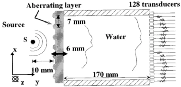
TRM are used to guide the wave field between the acoustic source and the array~Fig. 1!. The experimental results show that these walls combined with a TRM simulate a time-reversal cavity, and thus, greatly improve the focusing qual-ity. We also present a numerical simulation based on a finite differences scheme.
The experimental setup is presented on Fig. 1. An aber-rating layer is located 170 mm away from a transducer’s array in a water tank. The aberrations are created by periodic lenticular shapes on one side of the layer. Although real ab-errators will never have this particular shape, this strong pro-file was chosen among others because it induced the worst
a!Electronic mail: mathias@loa.espci.fr
FIG. 1. Experimental setup with walls: Walls confine the wave field on the aperture of the TRM, and thus, simulate a time-reversal cavity.
FIG. 2. Wave front received on the TRM without walls. On the vertical axis is the transducer number; on the horizontal axis, time inms. The pressure field amplitude is displayed in grey scale.
APPLIED PHYSICS LETTERS VOLUME 72, NUMBER 20 18 MAY 1998
2511
degradation of focusing. The time-reversal mirror is a linear array of 128 transducers ( fc53.0 MHz). Each transducer
has its own amplifier, an 8-bit analog-to-digital converter, a storage memory, and an 8-bit digital-to-analog converter working at a 20 MHz sampling rate. A single transducer S is used both as an acoustic source and a hydrophone. The setup is invariant under any translation along the z axis. This per-mits us to restrict the propagation to a two-dimensional~2D! problem in the 0xy plane.
A time-reversal process consists of three steps. In the first step, the acoustic source S emits a short signal. The generated wave front propagates through the aberrator and is received on the limited aperture of the array. In a second step, the 128 received signals are sampled, time reversed, and repeatedly retransmitted by the array. In the last step, S is used as an hydrophone to scan the pressure field along the x axis. The resulting directivity pattern characterizes the quality of focusing.
Figure 2 shows that the wave field received on the array exhibits not only phase but also amplitude aberrations. The directivity pattern after time reversal is plotted on Fig. 3. It is
compared with the optimal focusing in water and with the focusing obtained with adapted time delays ~i.e., phased ar-ray!. The time-reversal focusing is a little better than the adapted time-delay focusing, but remains very far from the optimum.
Now, two parallel and totally reflecting walls ~steel/ water interfaces! are placed on both sides of the array ~Fig. 1!. In this new configuration, Fig. 4 shows a second-order finite differences simulation of the propagation of the 2D scalar pressure field from the source to the array. This nu-merical simulation shows that an important part of the emit-ted wave front is diffracemit-ted by the propagation through the aberrating layer, deviated outside the array aperture, and would be lost without the two totally reflecting walls. The
FIG. 4. Simulation of the propagation through the aberrating layer at differ-ent time steps.
FIG. 5. Simulation of the TR focusing with@~a!, ~b!, ~c!# and without @~d!, ~e!, ~f!# reflecting walls at different time steps.
FIG. 6. Wave front received on the TRM with the two reflecting walls. FIG. 3. Time-reversal focusing in water~solid line!, through the aberrating
layer~dashed line!, and focusing through the aberrating layer ~dotted line! with a phased array.
walls reflect this part of the wave front that can now encoun-ter the array aperture. The signals recorded on the simulated transducers are then time reversed and reemitted by the ar-ray. In Fig. 5, we follow step by step the convergence of the time-reversed wave front on the focal spot in both cases, with@Fig. 5~a!# and without @Fig. 5~b!# the reflecting walls. The simulations results speak for themselves: taking advan-tage of the reflections on the boundaries, the TRM recreates the initial wave field much better than without walls@as seen by comparison of Figs. 4~b!, 5~b!, and 5~e!#. Thus, the use of totally reflecting walls is a way of overcoming the degrada-tion of focusing through strongly diffracting aberrating lay-ers.
The experimental results are in good agreement with the simulation. As is shown on Fig. 6, the experimental wave field received on the array now contains not only the previ-ously received wave front ~Fig. 2!, but also the two reflec-tions on the walls. After time reversal, we obtain the same directivity pattern as without the aberrating layer ~Fig. 7!. The quality of focusing is, therefore, at its best despite the strong aberrations.
One can remark on Fig. 3 and Fig. 7 that the time-reversed focal beam is much thinner~1.2 mm! with the two walls than in unbounded water ~2.5 mm!: The walls drasti-cally improve the spatial resolution of the array. Roux et al.3 interpreted it by the principle of mirror images in a medium bounded by two walls: An observer located at the source point S does not only see the real transducers array but also its vertical images through the mirrors ~Fig. 8!. When the array reemits the time-reversed wave front presented in Fig. 6, it is identical to the reemission of both the direct wave front by the real TRM together with two unwrapped wave fronts originating from the virtual images~Fig. 8!. Thus, we obtain the same focusing as if we had used a larger TRM
reemitting a single unwrapped wave front. The array’s aper-ture is increased by the reflections on the walls. Taking into account the first two images, the array aperture is multiplied by 3, and the theoretical spatial resolution of the system is improved by a factor of 3. In our experiment, though, the resolution is only two times better than in unbounded water. This lower gain can be explained by the apodization of the emitted signal due to the transducer’s angular directivity.
In conclusion, we have presented experimental results as well as numerical simulations of focusing through highly aberrating layers. Classical techniques fail, whereas the TRM together with adequate boundary conditions ~steel walls! simulate a time-reversal cavity. This leads to an optimal fo-cusing, which completely compensates for the aberrations and improves the spatial resolution. This method could be very useful for all applications demanding a fine resolution despite the presence of strong aberrations ~medical imaging, NDT!. Moreover, in underwater acoustics, the TRM could take advantage of the sea/air interface, which behaves as a totally reflecting wall.
1M. Fink, Phys. Today 50, 34~1997!.
2C. Dorme and M. Fink, J. Acoust. Soc. Am. 98, 1155~1995!. 3
Ph. Roux, B. Roman, and M. Fink, Appl. Phys. Lett. 70, 1811~1997!. FIG. 7. Experimental results: Time-reversal focusing in water~black line!
and through the aberrating layer~dashed line! with the reflecting walls. The 26 dB beamwidth is equal to 1.2 mm in both cases.
FIG. 8. Virtual increasing of the array aperture by the reflections on the two walls: S ‘‘sees’’ the real TRM, plus the two virtual images.
2513 Appl. Phys. Lett., Vol. 72, No. 20, 18 May 1998 Tanter, Thomas, and Fink