HAL Id: cea-02435092
https://hal-cea.archives-ouvertes.fr/cea-02435092
Submitted on 10 Jan 2020
HAL is a multi-disciplinary open access
archive for the deposit and dissemination of
sci-entific research documents, whether they are
pub-lished or not. The documents may come from
teaching and research institutions in France or
abroad, or from public or private research centers.
L’archive ouverte pluridisciplinaire HAL, est
destinée au dépôt et à la diffusion de documents
scientifiques de niveau recherche, publiés ou non,
émanant des établissements d’enseignement et de
recherche français ou étrangers, des laboratoires
publics ou privés.
phase
P. Amphoux, P. Gama, L. Raquin, B. Levoir
To cite this version:
P. Amphoux, P. Gama, L. Raquin, B. Levoir. Status of astrid architecture in starting of basic design
phase. ICAPP 2017, Apr 2017, Fukui And Kyoto, Japan. �cea-02435092�
Status of ASTRID architecture in starting of Basic Design phase Philippe AMPHOUX1, Philippe GAMA2, Loïc RAQUIN3, Benoît LEVOIR3
1: CEA Cadarache, DEN/DER/CPA, 13108 Saint-Paul lez Durance Cedex, France 2
: AREVA NP, 10 rue Juliette Récamier 69456 Lyon Cedex 06, France
3
: NOX, 45/47 Bd Paul Vaillant-Couturier 94200 Ivry-sur-Seine, France Contact author: Philippe AMPHOUX, +3344225711, philippe.amphoux@cea.fr
Abstract - Sodium-cooled Fast Reactors (SFR) is one of
the Generation IV reactor concepts selected to secure the nuclear fuel resources and to manage radioactive waste. In the frame of the June 2006 French act on sustainable management of radioactive materials and wastes, French Government entrusted CEA (French Commission for Atomic Energy and Alternative Energy) to conduct design studies of ASTRID (Advanced Sodium Technological Reactor for Industrial Demonstration) prototype in collaboration with fourteen industrial partners.
After 6 years of Conceptual Design phase, the Project is involved since January 2016 in Basic Design with a reference for the power conversion systems (PCS) in Brayton gas cycle in order to benefit from the use of a gas (pure nitrogen) non-reactive with sodium.
The first 10 months of 2016 were dedicated to a Confirmation of Configuration Phase (P2C) whose objectives were to revisit and optimize the different technical options considered as the reference configuration during the AVP phase.
The P2C was closed in October 2016 by a review which defined the new reference configuration for the Basic Design studies to be done. In addition, Balance Of Plant (BOP) studies considering the French reference site are going on.
This paper presents the status of the ASTRID architecture including a synthesis of the specificities of the site. The main items of the reference P2C configuration will be detailed: design of Na secondary loops and heat exchangers according to the Brayton cycle, handling fuel route including an external storage vessel in the reactor building, symmetric design of the nuclear buildings with two exchangers gas buildings and independent turbine associated.
Finally, the conditions of integration of the nuclear island buildings in the site and the general layout will also be exposed.
Items addressed in this document include 3D views of nuclear island buildings which have been designed by the industrial Partners and managed by CEA which acts as the industrial architect of the project.
I. INTODUCTION
After 6 years of Conceptual Design phase (AVP), the Project is involved since January 2016 in Basic Design. It is a four years duration phase with different milestone at the project level and also with the relevant ministry.
Conceptual Design phase was closed by obtaining the main award of the French Society of Nuclear Energy (SFEN) rewarding the great scientific contribution for the AVP of ASTRID. It also highlights the quality of the organization in partnership which was naturally prolonged for the Basic Design.
At the end of Conceptual Design phase, it was decided to consider as reference the power conversion systems (PCS) in Brayton gas cycle in order to benefit from the use of a gas (pure nitrogen) non-reactive with sodium.
The first two years of the phase will be dedicated to design and integrate this power conversion system in the ASTRID layout.
Until October of 2016, the Project activity was mainly dedicated to a Confirmation of Configuration Phase (P2C) whose objectives were to revisit and optimize the different technical options considered as the reference configuration during the Conceptual Design phase. The P2C phase was achieved in October 2016 by a review which defined the new reference configuration for the Basic Design studies.
From November 2016 to the end of 2017, the objective of the consolidation phase (PCR) is to raise gas PCS integration studies at the same level that was achieved for Water/steam PCS. A go/no go decision for Gas PCS integration will be organized at the end of 2017. The choice will include technical and cost consideration but also public acceptance requirements.
ASTRID Project current driver schedule for the Basic Design phase is shown in Fig 1, considering a 4 years period which could be extended after 2020.
Fig. 1. ASTRID Project driver schedule
After a short description of the organization with partnership and the associated project management, the current status of the ASTRID Project will be presented through a shot description of the configuration of the main components of the nuclear island.
Finally, the balance of plant will be discussed on the French reference site which was chosen to provide the studies in real conditions.
II. PROJECT MANAGEMENT II.A. ASTRID Project partnership
As defined in the 2006 Law of 28 June 2006 on the
sustainable management of radioactive materials and waste CEA/Nuclear Energy Division is responsible for the ASTRID project [1].
For the Basic Design phase, CEA has renewed the bilateral partnership for this new step, traducing the acceptance of the different partners to be involved in the ASTRID project. As shown in Fig. 2, there are now 14 bi-lateral partnerships connected to CEA for the next 4 years [3].
Since early 2016, the cooperation with Japan has increased and the design scope of work has been raised from3 to 9 task sheets (rèf.[5]).
The 3 first task sheets on design activities were: active decay heat removal system, Curie Point electro Magnet for control rods and seismic isolation system.
The new studies subjects are the following:
- Fabricability and thermomechanical calculations of the Above Core Structure,
- Fabricability of the Polar Table,
- Contribution to Design of the Core Catcher, - Thermohydraulic of the primary vessel, - Thermomechanical of primary vessel structures.
Fig. 2. ASTRID Project partnership
II.B. Project organization
The organizational Project structure has not changed since 2014 [3] and the synoptic structure is presented in Fig. 3.
As explained in ref. [2], CEA still acts as the Project manager from the definition of the main functional requirements to the assembly of the 3D mock up including performance control, configuration management and interfaces between elementary products.
The project management is totally organized since AVP on a cutting based on a Product Breakdown Structure (PBS) which is in constant evolution. (Fig. 4).
Fig. 4. Product Breakdown Structure (level 3) Each partner is responsible for a work package which is clearly defined as a pack of different elements of the PBS. This allocation allows to be sure to cover all the products of the Project and allows a clearly definition of the limits for the interfaces management.
At the starting of the Basic Design, it was decided to introduce the Working Breakdown Structure (WBS) as a new management tool. The WBS is built by the crossing of the PBS and a task list established by the Project team, as shown on Fig. 5. For the Basic Design phase, the task list is typically: dimensioning studies, conceptual and process studies, layouts and mock-up, list of equipment, operability and maintainability studies, and so on.
During this year, each partner has made, from their allocated part of the PBS, their « complete » WBS and their associated deliverables. This work precedes the constitution of coherent work batches for the construction of the allotment which would be retained for the building phase.
The general 3D mock up is already created and assembled by the Project with the AVEVA Plant Design Mangement System (V12.1) software which is used by all the partners (Fig. 19 at the end the paper show an example of building view with AVEVA PDMS model).
Fig. 5. Construction of the WBS
II.C. Project improvements in P2C for preparing the Basic Design configuration
During the P2C phase, it has been decided to implement integrated Working Groups (WG) to reopen some options or complete some demonstrations on specific items in order to define the reference of configuration for the basic design.
For each WG, the detailed objectives were:
- to include feedbacks from the previous phase to reduce costs and simplify systems,
- for few technical points: reopen the possibility of other technical choices,
- to master risks, costs and schedule, - to look for overall consistency. The concerned topics were: - Fuel handling,
- Decay Heat Removal (DHR) system and associated safety demonstration,
- Hot cell,
- Large components lifetime,
- Front and back End ASTRID fuel cycle,
- Nitrogen power conversion system opportunities, - Inspection in Service and repair,
- Electrical systems,
- Natural convection behavior,
- Nuclear island layout and constructability, - Core catcher optimization,
- Instrumentation and control,
- Regulatory analysis with nuclear pressured equipment.
All these items were checked and challenged during ten month through three main drivers: safety, cost killing and operability. Global consistency was also watched over.
For each subject a working group has been set up, led by project team representative and shared with the concerned Partners.
After more than 100 meetings, each working group has proposed a selection of technical options to be integrated in the reference configuration. A global configuration review including an expert group evaluation in October 2016 has allowed building the overall configuration which is the base of the Basic Design.
III. MAIN SKETCH OF ASTRID
CONFIGURATION STATUS AT THE END OF P2C PHASE
The aim of this part is to provide an overview of main evolutions between end of conceptual design and current basic design phase.
The main evolution is the replacement of the steam by gas in the power conversion systems (PCS) for which reference is now in Brayton thermodynamic cycle in order to benefit from the use of pure nitrogen non-reactive with sodium. During the P2C, it was also performed studies for the optimization of the handling fuel route, building layout, the reactor pit and the architecture of the decay heat removal system (DHR). Design work is still in progress on these subjects.
III.A. Nuclear Island and main components
III.A.1. Architecture of nuclear island in Brayton cycle
Main features of ASTRID architecture (primary circuit and main auxiliary structures) are:
- Pool Type Reactor, - Main and Safety vessels
- Advanced Reactor Pit design for long term sodium leak management,
- 3 Primary Pumps
- 4 Intermediate Heat Exchangers (IHX) (1 IHX per secondary Loop)
- 4 in-vessel DHR sodium-sodium Heat Exchangers (1 per DHR sodium loop)
- 1 complementary ex-vessel DHR heat exchanger implanted in reactor pit
- Primary fuel handling system based on double rotating plugs and a fixed two ramps refueling machine
- Associated auxiliary systems (primary sodium purification system, cover gas system…) During P2C, the design of DHR systems has been challenged regarding safety criteria and a new architecture was defined on the basis of 4 diversified systems, whose design is still under study:
- Operational system (IHX + secondary loop) used during normal shutdown states on PCS dedicated system,
- Active DHR safety main system (2 trains), - Passive DHR safety main system (2 trains), - Complementary safety diversified DHR system,
through the safety vessel (2 trains). Main features of Secondary Circuits are:
- 4 symmetrical Sodium Loops equipped with isolation valves,
- Associated auxiliary systems (safety pressure discharge system, sodium purification system, cover gas system…)
- 2 sodium gas heats exchanger (SGHE) per Loop - Connection to the Gas Power Conversion System
through a set of pipes and associated components (isolation, discharge…)
A sketch view of the reactor vessel and two of the 4 secondary loops is shown on Fig. 6.
Fig. 6: View of the reactor with 2 of its secondary loops
Fuel handling systems architecture is composed of: - In-vessel fuel storage,
- External buffer zone in sodium for fuel interim storage installed in reactor building ,
- Two ramps refueling machine between reactor and interim fuel storage vessel,
- Fuel pool long term storage installed in a dedicated fuel building,
- Experimental fuel hot cell installed in fuel building,
- Fuel transfer cask between reactor building and fuel building with washing pits.
Gas pipes to turbine hall SGHE
Reactor vessel
The handling management from reactor vessel to external buffer zone is shown on Fig. 7.
Fig. 7. Cutting view of main vessel and external buffer zone with two ramps refueling machine
III.A.2. Reference configuration of main buildings
Reactor building
The main function of the Reactor Building is to house the reactor and its primary auxiliary systems, the external buffer zone and its auxiliary systems as well necessary operational and maintenance systems.
Main features of the reactor building are:
- Concept of containment and sodium leakage management allowing a rectangular shaped building (management of sodium leakage energy release risk at the scale of the impacted room: “sodium risk compartmentalization” concept), with dedicated systems and rooms arrangement for sodium leakage risks management
- Reinforced concrete structure, with steel concrete structures for specific parts of the building such as the reactor pit,
- Integration of the above roof area in a dedicated compartment closed by a polar table,
- Integration of the sodium fuel temporary storage vessel in an area separated from the reactor area. This building is surrounded by the two sodium-gas heat exchangers buildings, the safety electrical building which includes the main control room and the safety DHR building. These 5 buildings are founded on a common seismic raft.
Sodium-Gas Heat Exchanger Buildings
Sodium-Gas Heat Exchanger (SGHE) is under development, and needs specific building architecture adaptations.
The main function of the two SGHE buildings is to house the secondary circuits and a part of the gas circuits, but also to house some of the DHR main circuits distributed around the Reactor Building.
Main features of the SGHE buildings are:
- Separation between Sodium circuits rooms (sodium leakage risks) in the lower part of the building and gas circuits rooms in the upper part, - Separation between safety DHR circuits rooms
and main secondary circuits rooms
- Provisions of handling devices and space for inspection and maintenance of SGHE in the upper part of the building
Different building concepts were studied during P2C. The reference concept integrates a dedicated SGHE handling hall in the upper part of the building (Fig 8).
Fig. 8: View of reactor building and SGHE buildings
Fuel Building and Maintenance Building
These two buildings are based on a common raft, although they are separated from a functional and safety point of view:
- The fuel building is composed of 3 main areas connected by the fuel transfer cask (washing pit and cask corridor area, fuel pool area, experimental hot cell area) and a hall for the reception and expedition of fuel containers
External buffer Two ramps refueling
machine
Fuel transfer cask
Handling halls for SGHE
- The maintenance building is composed of a large hall including different types of specialized maintenance installations (components washing and storage pits, hot cell for components examinations and reparation…) and an auxiliary building including different types of auxiliary rooms as well as Control Center for Fuel handling operation.
General arrangement of nuclear island
Nuclear Island arrangement is based on the so called “cross architecture” shown in Fig. 9, with the reactor building in the center of the cross and the four branches being constituted by the two opposite SGHE, the electrical building and the fuel and maintenance building.
The general arrangement of the building is the following:
- A set of buildings associated to primary and secondary circuits based on a seismic common raft: reactor building, SGHE buildings (x2), electrical building, DHR safety building,
- A set of fuel and maintenance buildings based on a non-seismic common raft
- Auxiliary building and galleries distributed according safety, functional and geographical requirements
Fig. 9. Nuclear island in cross
III.B. Turbine building with gas storage
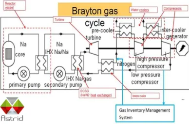
Brayton Cycles consists of a loop of nitrogen circulating from the SGHE to the turbine, within intercoolers, coolers and compressors. All these equipment are implemented on the first floor of the Turbine Building. In order to manage start-up, shutdown and other specific transients, the quantity of nitrogen contained in the Brayton Cycle (130 tons), so called Gas Inventory, can be withdrawn and reinjected by the Gas Inventory Management System.
The Brayton cycle is schematized in Fig. 10 with mention of the 2 connected point (high and low pressure) for management of the Nitrogen.
Fig. 10. Brayton cycle and gas management The gas inventory management system is composed with 6 large gas storage vessels (600 m3 under 50 bar each) which are implemented on the ground floor of the turbine building, below the Brayton Cycle equipment (Fig. 11). In addition, a liquid nitrogen storage unit, and a set of nitrogen cylinders under 200 bar, allow to perform first filling and continuous make-up (to compensate leakage) of the Gas Inventory.
Fig. 11. Turbine and gas storage building During the AVP2 phase, a techno-economic analysis has been conducted on the ASTRID gas PCS. A multiple parameters investigation concluded to an optimized configuration of the gas PCS with two turbomachinery shaft lines in two separate turbine halls. This configuration led to a strong reduction of the number of
Nitrogen tanker Turbine hall in Brayton
gas lines and equipment, of the steel and nitrogen inventories (divided by a factor 2) and of the gas supply system. In addition, the simplification of the gas piping layout allowed a better arrangement of the turbine hall with easier accessibility and maintainability.
IV. BALANCE OF PLANT
To implement studies in real conditions, a reference site was selected as a possible one. That makes it possible to apprehend the whole of the site interfaces with the installation design. A project management process ensures impacts follow-up on the reference site (geology, seismic conditions, climatology, external aggression, plugin to networks and so on) in order to manage and quantify them during studies. This approach allows to identify clearly all the design options linked to the reference site and to compare several sites between them.
IV.A. Main characteristics of Marcoule site as a possible one
This site has been chosen for its proximity with a CEA Center which bring a good preliminary knowledge of the environment (external hazards for example).
IV.A.1. Geography
The site of Marcoule is in the Rhodanian corridor, with a few kilometers north of the junction of the Rhone and Cèze.
The study site for ASTRID Project is located at the north of PHENIX reactor site now under decommissioning. It is localized between the Rhône river and mountain relief “La dent de Marcoule” which peaks in 218 meters of height, as shown on Fig. 12.
Fig. 12. General view of the site
IV.A.I1. Geology
The site is positioned mainly on the Eastern edge of the calcareous plate of the Cretaceous which forms the whole of the reliefs in the neighborhoods
This unit is locally covered in its oriental party, largely eroded by the valley of the Rhone, the clean sands allotted to an episode Pliocene, then by the alluvial terraces of the Rhone. Surface formations are locally present, in particular falls of slope and colluviums.
Local geology (fig. 13) was specified with the various following structures: The presence of massive likings to last carbonated to the South /South-West, Limestones in the west and the center of the site, sandy formation in North/North-West and surface formation in the East along the Rhone.
Limestones are very little fractured and are rather impermeable. The investigations carried out to date did not locate of karstic zone in this area.
The surface formations do not present a risk of liquefaction.
Fig. 13. Geologic map of the site
Rhône river
PHENIX Dent de Marcoule
IV.A.I1. Hydrology
The close proximity of the Rhône belongs to selection arguments as a study site. The Rhône is the largest French river guaranteeing a constant availability of flow and good thermal properties for cooling. Various hydraulic works guarantee also a good control of the levels of risings. The main features of the Rhone on the level of Marcoule are summarized in Table 1 hereafter.
TABLE I. Rhône’s characteristics at MARCOULE Characteristics Unit Value Flow (min) m3/s 335 Flow (average) m3/s 1590 T° (average) °C 15,3 T° (absolute maximum) °C 27,5 Majored Rising level mNGF 40
IV.A.II1. Footprint and Platform
A topographic surveyor statement was realized with altimetry and planimetry data. This statement was used to model the natural ground with GEOMEDIA COVADIS V.14 software.
The development of the platform has been performed with the followed main constraints:
• single platform with optimized surface,
• geologic constraints for the nuclear island,
• optimization of the ratio earthworks.
The principle of the single platform is retained to facilitate the positioning of the cranes in order to optimize the constructability and the associated schedule.
On these bases, the temporary platform level calculated, taking into account the bulking factor and re-using of materials on site, is 57.00 meters NFG (altitude). The surface, in order to integrate the Nuclear Island and all the utilities, is about 30 ha shown on Fig. 14.
Fig. 14. Platform simulation (COVADIS V.14)
IV.B. Site integration of Nuclear Island
IV.B.1. Reference Configuration
Different types of site arrangements were investigated during P2C. No less than 9 different layouts were involved with the following constraints:
- Choice of a seismic raft for the reactor island and its associated sodium circuits,
- Minimization of sodium pipes length (sodium risk leakage management),
- Minimization of gas pipes length between Nuclear Island and Conventional Island,
- Need for an on-site manufacturing facility (manufacturing of non-transportable large components) during civil works,
- Open-top construction concept using a dedicated heavy load crane,
- Needs for space for construction around the main buildings.
Two integration site options have been selected and are still under study: one taking into account the constraints of the Marcoule Site (shown in Fig 15) selected as a refrence and another concept without specific site constraints, studied as an alternative.
For the Marcoule arrangement shown in Fig. 16, the turbine buildings are installed in parallel and in a position allowing to minimize the gas pipes length in respect of the construction constraints (positioning of cranes).
Fig. X. General view of the site
Fig. 15. Nuclear island and turbine buildings architecture
IV.B.1. Implementation of nuclear building on the site
The main constraints to be taken into account for the implementation on Marcoule Site are:
Nuclear Island
Turbine buildings Gas pipes
- Site geology: necessity to found the main and heavy buildings on rock and not on alluvial ground,
- Site hydrology: necessity to select a platform level overall flooding risk and to insure a water gravitational draining from the platform and from the foundations
- Site topography: the presence of the Rhône River at the East and of the Marcoule Hill to the West limits the width of the useful part of the site. As a consequence, the main buildings are preferably arranged according the North-South axis and the level of the main foundations is a compromise between the shape of the rock substratum and the maximal level of the Rhône water.
The following figure Fig. 16 proposes a cutting view in the East/West direction.
Fig. 16. EAST/WEST cutting view of the nuclear island
IV.D. General Layout
The P2C phase with the different stated options, led to produce a new global layout as presented on FIG. 17.
In synthesis, the main evolutions compared to end of conceptual design phase layout are:
- decrease platform level from 62 to 57 mNGF, - 2 turbine buildings connected to the nuclear
island by gas pipelines and including the nitrogen tankers at the ground floor,
- new design of gas sodium heat exchangers, - addition of nuclear waste (solid and liquid)
building,
- integration of constructability constraints in the distances between buildings.
Fig. 17. Global layout of ASTRID at starting of Basic Design
IV. C Integration around the site
In order to consider real site integration, it has been studied the connection for the main ASTRID facilities: power and water supply.
IV.C.1. Connection to the power supply network
Astrid will be connected to the existing electrical networks around the site:
- a main connection to the domestic network 400kV,
- a second auxiliary connection to the 225kV network.
The main connection 400kV is designed to allow both:
- total evacuation of the energy produced by the turbine generator set towards the general network,
- the general supply of the whole site auxiliaries. The auxiliary connection in 225kV can only supply the site auxiliaries in case of problem with the main network.
IV.C.2. Connection to the Rhône
The proximity of the Rhône is taken into account for the water supply in operating but it will be considered as a logistic way during the building phase.
Extreme rising level
Auxiliary and administrative buildings
Nuclear Island Cooling Tower
Waste building Turbine building
An harbor is planned for the evacuation of the earthwork materials and the delivery of the voluminous equipment of the nuclear island during all the works. Because of limited surface, the design of the RO- RO docks (roll on and roll off), loading and unloading docks without crane has been adopted. The harbor will allow the simultaneity docking of one barge with another one in standby. The biggest barge which can be used on the Rhône river has a 2 400 ton capacity, 80 meters of length for 11 meters of wide.
In operation, Rhône will be used for supplying the ASTRID water needs: make-up for the main cooling system, direct cooling for safety functions, fire water supply, raw water, potable water and demineralized water. A Water Intake, implemented along the Rhône will be built and connected to a pump station equipped with filters as shown on figure 18.
Fig.18 : Pumping building with the Rhône connection (PDMS model)
V. CONCLUSIONS
This paper presents a status of the ASTRID Project at the starting of the Basic Design in particular on building layout and associated Balance of Plant.
The main goal for the first step, P2C phase, was to define the ASTRID reference configuration for the next three years.
The P2C phase was closed in October 2016 by a technical review which defined the new reference configuration for the Basic Design. Many subjects are still under studies like: optimization of DHR system design, secondary loops design for the natural convection, detailed design of the handling system components, SGHE handling concept in accordance with inspection
and maintenance requirements, Balance of Plant optimization to master the integration site constraints and so on.
The next objective to come at the end of 2017 will be to raise Gas PCS integration for a go-no go decision on the thermodynamic cycle.
ACKNOWLEDGMENTS
Special acknowledgments to Philippe GAMA form AREVA NP, Loïc RAQUIN and Benoît LEVOIR from NOX for their participation to this paper.
Special thanks to Frederic VARAINE and Gilles RODRIGUEZ from CEA for assistance and comments that greatly improved the manuscript.
REFERENCES
1. F. GAUCHE; The French Prototype of 4th Generation Reactor: ASTRID; Annual meeting on nuclear technology, Berlin, May 17&18th; 2011. 2. P. ALPHONSE, Status of ASTRID architecture and
pre-conceptual design, IAEA-CN-199, Paris France, 4-7 March 2013, Paper CN-199-275.
3. E. ABONNEAU and al, “The ASTID Project: Status and Prospects towards the conceptual design phase”, ICAPP 2014, Charlotte (2014).
4. G. RODRIGUEZ and al, “Qualification program of the ASTRID SFR project: Definition, Methodology and associated Risk Evaluation and management”, ICAPP 2015, Nice (2015).
5. J. ROUAULT, ASTRID The SFRGENIV Technology Demonstrator Project: Where we are, where do we stand for?, ICAPP2015, Nice France, 3-6 may 2015, Paper 15439.
Rhône intake Pumping building
Automatic Chain filters