HAL Id: hal-01867475
https://hal.archives-ouvertes.fr/hal-01867475
Submitted on 8 Jan 2019
HAL is a multi-disciplinary open access
archive for the deposit and dissemination of
sci-entific research documents, whether they are
pub-lished or not. The documents may come from
teaching and research institutions in France or
abroad, or from public or private research centers.
L’archive ouverte pluridisciplinaire HAL, est
destinée au dépôt et à la diffusion de documents
scientifiques de niveau recherche, publiés ou non,
émanant des établissements d’enseignement et de
recherche français ou étrangers, des laboratoires
publics ou privés.
Charged iodide in chains behind the highly efficient
iodine doping in carbon nanotubes
Ahmed Zubair, Damien Tristant, Chunyang Nie, Dmitri Tsentalovich, Robert
Headrick, Matteo Pasquali, Junichiro Kono, Vincent Meunier, Emmanuel
Flahaut, Marc Monthioux, et al.
To cite this version:
Ahmed Zubair, Damien Tristant, Chunyang Nie, Dmitri Tsentalovich, Robert Headrick, et al..
Charged iodide in chains behind the highly efficient iodine doping in carbon nanotubes.
Physi-cal Review Materials, American PhysiPhysi-cal Society, 2017, 1 (6), pp.064002.
�10.1103/PhysRevMate-rials.1.064002�. �hal-01867475�
OATAO is an open access repository that collects the work of Toulouse
researchers and makes it freely available over the web where possible
Any correspondence concerning this service should be sent
to the repository administrator:
[email protected]
This is a Publisher”s version published in:
http://oatao.univ-toulouse.fr/21004
To cite this version:
Zubair, Ahmed and Tristant, Damien and Nie, Chunyang and
Tsentalovich, Dmitri E. and Headrick, Robert J. and Pasquali,
Matteo and Kono, Junichiro and Meunier, Vincent and Flahaut,
Emmanuel and Monthioux, Marc
and Gerber, Iann C. and Puech,
Pascal Charged iodide in chains behind the highly efficient iodine
doping in carbon nanotubes. (2017) Physical Review Materials, 1
(6). 1-7. ISSN 2475-9953
PHYSICAL REVIEW MATERIALS 1, 064002 (2017)
Charged iodide in chains behind the highly efficient iodine doping in carbon nanotubes
Ahmed Zubair,1Damien Tristant,2,3,4Chunyang Nie,3,5Dmitri E. Tsentalovich,6Robert J. Headrick,6,7Matteo Pasquali,6,7,8
Junichiro Kono,1,8,9Vincent Meunier,2Emmanuel Flahaut,10Marc Monthioux,3Iann C. Gerber,4and Pascal Puech3,*
1Department of Electrical and Computer Engineering, Rice University, Houston, Texas 77005, USA 2
Department of Physics, Applied Physics, and Astronomy, Rensselaer Polytechnic Institute, Troy, New York 12180, USA
3CEMES-CNRS, UPR-8011, Université Fédérale de Toulouse-Midi-Pyrénées, Toulouse, France 4LPCNO, UMR-5215 CNRS, INSA, Université Fédérale de Toulouse-Midi-Pyrénées, Toulouse, France
5School of Environmental Science and Engineering, Guangdong University of Technology, Guangzhou, 510006, P. R. China 6Department of Chemical and Biomolecular Engineering, Rice University, Houston, Texas 77005, USA
7
Department of Chemistry, Rice University, Houston, Texas 77005, USA
8Department of Materials Science and NanoEngineering, Rice University, Houston, Texas 77005, USA 9Department of Physics and Astronomy, Rice University, Houston, Texas 77005, USA
10Institut Carnot CIRIMAT, Université Fédérale de Toulouse-Midi-Pyrénées, UMR CNRS 5085, Toulouse, France
(Received 26 September 2017; published 27 November 2017)
The origin of highly efficient iodine doping of carbon nanotubes is not well understood. Relying on first-principles calculations, we found that iodine molecules (I2) in contact with a carbon nanotube interact to form
monoiodide or/and polyiodide from two and three I2as a result of removing electrons from the carbon nanotube
(p-type doping). Charge per iodine atom for monoiodide ion or iodine atom at end of iodine chain is significantly higher than that for I2. This atomic analysis extends previous studies showing that polyiodide ions are the dominant
dopants. Moreover, we observed isolated I atoms in atomically resolved transmission electron microscopy, which proves the production of monoiodide. Finally, using Raman spectroscopy, we quantitatively determined the doping level and estimated the number of conducting channels in high electrical conductivity fibers composed of iodine-doped double-wall carbon nanotubes.
DOI:10.1103/PhysRevMaterials.1.064002
I. INTRODUCTION
Single-wall, double-wall, and multiwall carbon nanotubes (SWCNTs, DWCNTs, and MWCNTs, respectively) are quasi-one-dimensional materials that have the structure of rolled-up graphene sheets [1–5]. Individual Carbon nanotubes (CNTs) have some extraordinary properties such as ultrahigh electrical and thermal conductivity [6,7], light weight and high mechan-ical strength [8], which make them promising for various applications, including solar energy [9], electronics [10], and biomedical technology [11]. However, these excellent properties often drastically diminish in macroscopic form, e.g., films, sheets, fibers, ropes, wires, and cables of CNTs. Recently, reports on doped CNT fibers [12–14] have revealed ultrahigh electrical conductivity. These macroscopic fibers are a candidate for replacement of metals as a universal conducting wire and will have a wide range of applications, such as aeronautics, space, power transmission, and automobile industry [15].
Iodine (I2) is known to be an efficient dopant for CNTs,
but the doping mechanism is not well understood. Recent ab
initiocalculations of graphene doping by iodine suggested that various iodine species should be considered [16,17]. Even though many characterization studies have been conducted on doping processes in CNTs [18–20], the mechanism of iodine doping remains a long-debated subject. Tri-iodide (I−
3)
and pentaiodide (I−
5), which are easily observable by Raman
scattering, have been reported to be at the origin of doping [21], but the large conductance enhancement observed is not
*Corresponding author: [email protected]
in agreement with the charge carrier concentration estimated by first-principles calculations. Moreover, monoiodide ions (I−) have been observed with Mössbauer spectroscopy with a
large charge transfer for iodine doping of CNTs [22]. In this work, we try to explain the great gain of conductivity associated with iodine doping. We first start our study by first-principles calculations. We unambiguously demonstrate the formation of chain of charged iodide and the corresponding low-energy cost for the creation of monoiodide. Then, by studying Raman spectroscopy in DWCNTs well-purified assembled in fibers and doped with iodine, and compared with calculations performed on SWCNTs associated with I and TEM images obtained on iodine chains encapsulated in moderately purified DWCNTs.
II. METHODS A. First-principles calculations
We performed first-principles calculations based on density functional theory (DFT). The structural and electronic proper-ties of CNT systems were obtained with the Vienna ab initio simulation package (VASP) [23–26]. The plane-wave basis set
cutoff energy was set to be 400 eV with a Gaussian smearing method of 0.005 eV width, in order to ensure well-converged total energy and force values. To properly account for van der Waals interactions, we used theOPTB86B-VDWscheme [27],
based on previous work on carbon-based systems [16]. All atoms were allowed to relax until the maximum of forces acting on them became smaller than 0.01 eV ˚A−1.
These calculations were performed for iodine-filled (7,7) and (9,9) SWCNTs and also for (7,7), (9,9), (11,11), (13,13),
AHMED ZUBAIR et al. PHYSICAL REVIEW MATERIALS 1, 064002 (2017)
and (15,15) SWCNT bundles containing iodine between nanotubes. We also added the case of (10,10)@(15,15) DWCNTs which correspond to CNTs in doped fibers. Initial SWCNT geometries were generated by the TUBEGEN code [28]. The calculated supercell (1 × 1 × 10) used for both isolated SWCNTs and SWCNT bundles contained four iodine atoms. For the case of (11,11) SWCNT bundle containing six iodine atoms, a supercell (1 × 1 × 14) was used. For the isolated SWCNT, we used a separation of 3 and 5 nm in two perpendicular directions with respect to the CNT axis direction for (7,7) and (9,9) SWCNT systems, respectively, in order to avoid interaction between two adjacent periodic structures. For the SWCNT bundle, a hexagonal lattice was used. The k-point sampling was always based on a Ŵ-centered grid for all types of calculations. A (1 × 1 × 2) grid and a (2 × 2 × 2) grid were used to optimize isolated CNT and a CNT bundle system, respectively. Then, a (1 × 1 × 5) grid and a (5 × 5 × 5) grid were used to determine the charge transfer of an isolated CNT and a CNT bundle, respectively. Bader charge analysis was carried out using Henkelman’s Group program [29–31].
For comparison, we also calculated the adsorption energy of eight adsorption sites of an I2 molecule adsorbed on
two different CNTs: a (7,7) metallic armchair and a (11,0) semiconducting zigzag CNTs, with a small diameter (around 0.9 nm). Since no significant changes were observed, with adsorption energy difference lower than 0.01 eV, we performed all our energy studies on metallic systems. In a previous work of Tristant et al. [32] (main text and electronic supplemental information), we also analyzed the case of highly doped CNTs with large diameter and found a similar Fermi level shift for both semiconducting and metallic CNTs.
To fill the CNTs, oxidation allows iodine going inside. On the contrary, to obtain high conductive CNTs fiber, the CNTs should be free of defects to have a large electronic mean-free path and, therefore, no oxidation is present. Consequently, in our scenarios, the case of having both situations was disregarded, not for technical difficulties but as it did not correspond to our samples.
B. Iodine-doped CNT-fiber production
The CNT fibers used in this study were produced from well-purified DWCNTs (residual catalyst content less than 5% and no amorphous residue) by the wet-spinning process reported by Behabtu et al. [12]. During the manufacturing process, these fibers were doped inherently by chlorosulfonic acid. We later annealed the fibers to remove the doping species originating from the superacid according to the method in Ref. [12]. Such annealed (and thus close to pristine) fibers were then kept in an iodine vapor chamber for 24 h at 200◦C
to ensure a high degree of doping.
C. Raman spectroscopy
Raman spectroscopy experiments were performed at room temperature with a 568-nm excitation wavelength laser using a T64000 Jobin-Yvon Horiba spectrometer in a backscattering configuration on an iodine-doped CNT fiber. The laser power was kept below 0.4 mW, and the laser beam was focused onto the sample with an objective lens with a magnification of ×40.
D. Electrical conductivity measurements
For electrical conductivity measurements of iodine-doped fibers, we used a home-built nitrogen-purged transport mea-surement system. We used a square U-shaped epoxy glass substrate to suspend the fiber. We used a four-terminal con-figuration: silver paste was used to make contact between the fiber and gold wires, which were connected to the connection pins of a cryostat sample holder. We placed the sample on the cryostat sample holder that was kept in a vacuum-sealed chamber. The chamber was initially pumped down to a few tenths of pascal, and then nitrogen gas was introduced into the chamber. We followed a similar procedure to that described by Xuan et al. [13] for current-carrying capacity measurements. Current through the fiber was swept up at a certain value (which was increased by step at each cycle) and then swept back to 1 mA. The resistance of the sample was continuously recorded during the current sweeping cycles. The current value was increased until the fiber broke. We measured the diameter of fibers using an optical microscope.
E. Transmission electron microscopy
For transmission electron microscopy (TEM) experiments, another set of samples was prepared [33,34] for which iodine from the vapor phase was introduced inside DWCNTs (midly purified, with HCl only in order to remove the excess of catalyst Co nanoparticles) in order to observe the arrangement of the iodine atoms clearly. First, dry, raw DWCNTs along with iodine rocks were ground in a mortar together to obtain a homogeneous mixture. The mixture was transferred into a quartz ampoule. The ampoule was sealed and placed into a furnace. The furnace temperature was slowly (5◦C/min)
ramped up to 827◦C and kept at 827◦C for 24 h and then slowly
(0.1◦C/min between 827◦C to 777◦C and 1◦C/min down to
room temperature) ramped down to room temperature. Once the heating process was completed, the ampoule was taken out of the furnace, and the composite powder taken out from the ampoule was ground into a fine powder. The powder was washed with ethanol to dissolve the residual iodine. To prepare a TEM specimen, the iodine-filled DWCNT samples were dispersed in ethanol using a sonication bath. Then, a few drops of suspension were deposited onto a copper grid (200 mesh) coated with a lacey-type carbon film using a glass pipette. After the evaporation of the ethanol from the grid, the specimen was ready for observation. These iodine-filled DWCNTs were imaged by a JEOL JEM-ARM200F microscope (200 KV) equipped with a STEM and Cs corrector for the condenser lens.
III. RESULTS AND DISCUSSION A. First-principles calculations
To find if the mechanism at the origin of the ultrahigh conductivity is the activation of electronic channels due to the large Fermi level shift originating from iodine doping, we considered the interaction between two iodine molecules and CNT walls to form charged species from charge transfer. Since the dissociation of a single I2 on graphene is clearly
unfavorable (+0.74 eV) [17], more molecules should be considered. First, we calculated interaction of four iodine atoms inside a SWCNT and between SWCNTs inside a
CHARGED IODIDE IN CHAINS BEHIND THE HIGHLY . . . PHYSICAL REVIEW MATERIALS 1, 064002 (2017) (a) (d) (b) (e) (c) (f) (a) ( ) (d) (b) (e) (c) (f)
System 1 System 2 System 3
FIG. 1. View of the different intercalation sites of (a) I2, (b) Iδ1−+
Iδ3−
3 , and (c) I δ4−
4 inside a (7,7) SWCNT, (d) 2I2, (e) Iδ1−+ Iδ33−, and
(f) Iδ4−
4 on a (7,7) SWCNT bundle.
bundle. To compare the energy stability between system 1 (2I2+ SWCNT) and system 2 (Iδ1−+ Iδ33−+ SWCNTδCNT+),
where δ is the estimated charge transfer, we used the following equation:
1E = Esystem2− Esystem1, (1)
and the same approach for system 3 (Iδ4−
4 + CNTδCNT+).
Both configurations, iodine filling the SWCNT and iodine in the SWCNT bundle, of systems 1, 2, and 3 are illustrated in Fig.1. The energy difference 1E values of doped CNT systems are shown in TableI. For the chiralities of (7,7) and (9,9), the tube diameter is 0.95 and 1.22 nm, respectively. The interaction of 2I2 leads to a reduction of energy for
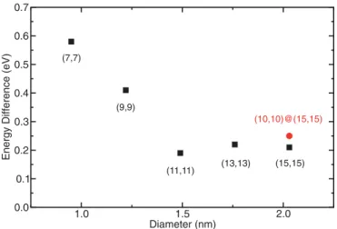
iodine atoms inside CNTs and iodine atoms in the CNT bundle. Insertion or adsorption configurations help stabilize the monoiodide and tri-iodide as well as the tetraiodide. Tetraiodide is more favorable, but the energy difference is not large enough to be the unique species at room temperature. In order to know if tetraiodide is always the more stable configuration, we calculated the energy difference between systems 2 and 3 for diameters up to 2 nm. We also considered the systems 2 and 3 for (10,10)@(15,15) DWCNT bundle. For large diameter tubes, we noted that the cylinders become deformed due to van der Waals interaction. The energy difference is reported in Fig. 2. For a diameter larger than 1.4 nm, the energy difference is constant and close to 0.2 eV.
TABLE I. Energy difference between systems 2 and 1 and 3 and 1 (eV), for the doped-inside isolated SWCNT and the doped SWCNT bundle. The first values are from the (7,7) SWCNT systems and the values between parentheses are from the (9,9) SWCNT systems.
System 1E(eV) Inside 1 (I2) 2¡Iδ3− 3 + Iδ− ¢ −0.68 3¡Iδ4− 4 ¢ −0.76 Bundle 1¡I2¢ 2¡Iδ3− 3 + Iδ− ¢ −0.83(−0.67) 3¡Iδ4− 4 ¢ −1.41(−1.08) 1.0 1.5 2.0 Diameter (nm) 0.0 0.1 0.2 0.3 0.4 0.5 0.6 0.7
Energy Difference (eV)
(7,7)
(9,9)
(11,11) (13,13) (15,15) (10,10)@(15,15)
FIG. 2. Energy difference (eV) between Iδ1−+ Iδ3− 3 and I
δ4− 4
for (7,7), (9,9), (11,11), (13,13), (15,15) SWCNT bundles and (10,10)@(15,15) DWCNT bundles. The Iδ4−
4 CNT system remains
the most energetically stable. 0.2 eV corresponds to 2300 K.
This value is quite small and can be viewed as an accurate estimate of the energy barrier for the transformation of I4 to
I3+I. Indeed, our attempt to estimate the transition state using
nudge elastic band type of calculations on the (9,9) bundle from I4to I3+I configurations provide us a late transition state
of less than 10 meV higher than the I3+I energy.
The bond lengths between iodine atoms of I2, Iδ33−, and I δ4− 4
species, for the doped-inside isolated SWCNT and the doped SWCNT bundle, are shown in TableII. The bond lengths in Iδ3−
3 and Iδ44− are longer than that of I2 (2.72 ˚A). The bond
length increase is correlated to the charge transfer on each atom forming the bond.
The estimated charge transfer values are summarized in TableIII. The value of δ is connected to the modification of the I-I bond length (see Table II and Fig. 3). There is no charge transfer when I2 is in a CNT bundle as it is a stable
state for iodine. But, charge transfer happens when di-iodide is inside CNTs. The bond length increase is due to electron transfer from the CNT to the iodine. These results indicate that the diameter of CNTs plays a significant role towards the stability of iodine species when iodine fills the CNTs. Most importantly, the charge per iodine atom for monoiodide is much higher than for other species which agrees with the
TABLE II. The bond distance (in ˚A) between iodine atoms belonging to I2, Iδ33−, and Iδ44−species, for the doped inside isolated
SWCNTs and the doped SWCNT bundles. The first values are from the (7,7) SWCNT systems and the values between parentheses are from (9,9) SWCNT systems.
Species Bond length ( ˚A)
Inside I2 2.87 Iδ3− 3 [2.98 2.98] Iδ4− 4 [3.12 2.99 3.13] Bundle I2 2.72(2.71) Iδ3− 3 [2.88 2.89]([2.89 2.89]) Iδ4− 4 [3.12 2.86 3.13]([3.21 2.85 3.15]) 064002-3
AHMED ZUBAIR et al. PHYSICAL REVIEW MATERIALS 1, 064002 (2017) (d) (a) (b) (c) E= 0.50 eV E= 1.54 eV 2.71Å 2.71Å 2.71Å 0.01 0.01 0.01 0.01 0.01 0.01 0.27 0.000.26 0.27 0.26 0.00 2.92 Å 2.92 Å 2.92 Å 2.92 Å E= 1.17 eV 2.71Å3.04 Å 2.95 Å 3.04 Å 0.01 0.010.32 0.080.08 0.34 0.31 0.22 0.00 0.27 0.32 0.05 2.94 Å 2.93 Å 3.39 Å 2.93 Å 2.94 Å (d)
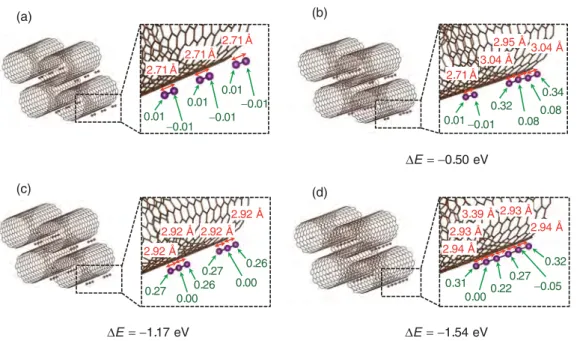
FIG. 3. View of the different intercalation sites of (a) 3I2, (b) Iδ44−+ I2, (c) 2Iδ33−, and (d) I δ6−
6 on a (11,11) SWCNT bundle with their bond
length (red color) and charge transfer per atom (green color). Energy difference 1E between 3I2and other systems is provided. The Iδ66−CNT
system is the most energetically stable.
Mössbauer finding [22]. For the bundle, the doping due to this process is also really large and consistent with the high electrical conductivity reached by the iodine-doped DWCNT fiber, as described in latter paragraphs.
To extend our study to larger polyiodine chains, as observed experimentally, we calculated four configurations involving up to six iodine atoms: 3I2, Iδ44−+ I2, 2I3δ3−, and Iδ66−. In Fig.3,
the configuration as well as the bond length and the charge transfer for each iodine atom are reported. The iodine atoms at the ends of each iodide species account for the highest amount of charges. The Iδ6−
6 is the most stable but the bond
length in the middle is very large and this configuration is close to 2Iδ3−
3 . Interestingly, a clear distinction in the type
of polyiodides seems difficult because the charge transfer for each atom within a chain is different. The charge is not fully delocalized over all atoms. The bond length is directly related to the charge of each atom constituting it. Mind that in these calculations, we completely neglect temperature effects (0 K calculations) and large fluctuations of bond lengths may arise from higher temperatures.
B. Transmission electron microscopy
Using TEM, we observed the arrangement of the iodine atoms filling the inner cavity of DWCNTs (Fig.4). The annular
TABLE III. Transferred charge per iodide ion species δ, for the iodine-doped-inside isolated SWCNT and the doped SWCNT bundle. The first value is for the (7,7) SWCNT, and the value between parentheses is for the (9,9) SWCNT.
Iδ1− Iδ3− 3 I δ2− 2 I δ4− 4 δ Inside 0.64 0.84 0.33 1.11 Bundle 0.32(0.39) 0.38(0.50) 0.00(0.00) 0.68(0.88)
dark field image from TEM clearly shows that iodine is able to form encapsulated linear chains inside DWCNTs exhibiting the suitable inner diameter [35]. As the annular dark field is highly sensitive to variations in the atomic number of atoms in the sample, iodine atoms, with atomic number 53, are much brighter than carbon atoms from the CNTs. Hence, the CNT are hardly seen. In Fig.4, we can see bright dots, each corresponding to iodine atom, and forming chains. There are two such iodine chains inside two DWCNTs in the figure. Monoiodides and polyiodides can be found in this TEM image. We indicated the occurrence of monoiodides using white solid arrows and that of tri-iodide with white, dashed arrows. The interaction between I2molecules that subsequently leads to the
formation of ion species with a high doping density is therefore further ascertained by both our calculations and atomically resolved TEM image.
C. Electrical conductivity
To determine the conductivity increase due to iodine dop-ing, we measured the current-carrying capacity of the iodine-doped fibers. Iodine-iodine-doped fibers had a conductivity of 6.5 ± 0.1 × 10⁶S m−1, which is higher than that of chlorosulfonic
FIG. 4. TEM images of iodine-filled DWCNTs. Two chains of iodine inside two DWCNTs are shown here. White, solid arrows show the presence of monoiodide species, and white, dashed arrows show the presence of tri-iodide species.
CHARGED IODIDE IN CHAINS BEHIND THE HIGHLY . . . PHYSICAL REVIEW MATERIALS 1, 064002 (2017)
FIG. 5. Plot of the conductivity values measured after a current-sweeping cycle as a function of applied peak current density used for the cycling series.
acid-doped fibers [32]. From Fig.5, we can see that at low current densities (below 330 MA m−2), the conductivity of the
iodine-doped fiber remains constant. Above a threshold value of current density (above 360 MA m−2) in cyclic conditions
[13], spontaneous dedoping of the fiber occurs due to Joule effect (at a temperature around 110 ± 30◦C), resulting in a
sudden drop in conductivity. The conductivity decreases by about 6, corresponding to the removal of iodine dopants. We repeated this experiment several times, and the conductivity drop factor was confirmed to always be in the range of 5 to 7.
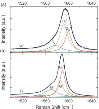
FIG. 6. Raman spectra in the G-band regime of (a) iodine-doped and (b) dedoped fibers. The blue and black solid lines represent experimental and theoretical fits data, respectively. The green, purple, brown, and red solid lines represent the G−
i , G−o, G+i, and G+o peaks,
respectively.
TABLE IV. Raman shift, ω (cm−1), and FWHM (cm−1) of fitted
four Lorentzian peaks for Raman spectra of the doped and dedoped fibers. We estimated uncertainty for ω and FWHM to be lower than 1 cm−1(1%). G− i G−o G+i G+o Doped fiber ω(cm−1) 1516 1577 1592 1600 FWHM (cm−1) 100 29.8 16.8 14.0 Dedoped fiber ω(cm−1) 1522 1570 1586 1590 FWHM (cm−1) 100 26.9 12.5 11.6 D. Raman spectroscopy
To determine the doping level, we acquired Raman spectra on both iodine-doped and dedoped fibers. Figure 6 shows the Raman G bands of (a) an iodine-doped DWCNT fiber and (b) a dedoped DWCNT fiber, fit with four Lorentzians. We previously described how this decomposition analysis provides information on doping [32]. These four peaks represent the upper (G+) and lower (G−) branches of the
inner (Gi) and outer (Go) tube characteristics of the G band of
DWCNTs. TableIVsummarizes the frequencies (ω) and full width at half maximum (FWHM) of the four Lorentzian peaks. G−
o, G+i , and G+o of the iodine-doped fiber were blue-shifted
compared to the dedoped fiber.
The G-band shift associated with the inner tube is due to the lattice contraction of the outer tube. From the 6 cm−1shift
of the G+
i bands between the doped and dedoped fibers, we
estimated the shift due to bond contraction for the outer tube to be 1.7 × 6 = 10 cm−1 (the factor 1.7 comes from strain
transmission between the outer and inner tubes [36]). This value corresponds to the shift of the G+
o band between the
doped and dedoped fibers. Therefore, we can conclude that no adiabatic effect is present based on the formulation in our previous work [32]. From this shift, it is possible to estimate the charge transfer factor per carbon atom: fC= 10/350 =
0.029 and, then, the average Fermi level shift by h1EFiN =
6.04√fC= 1 eV, a relation that is only valid for very large
doping (fC>0.007) [32].
Due to the high level of doping, there are multiple conductance channels that are occupied by charge carriers. To estimate the number of conducting channels, a full calculation could be done as in our previous work [32], but a rough estimation is also possible using Ei(eV) = (γ0aC−Ci)/d =
0.38i/d(nm)[37] (metallic i = 0, 3, 6, . . . , semiconducting i = 1, 2, 4, 5, 7, 8, . . . ). Before doping, a statistical analysis gives1
3metallic (2 channels) and23semiconducting (0 channel)
for inner and outer tubes. The number of conducting channels for a DWCNT is 43 on average. As the outer diameter is ∼2 nm, by moving the average Fermi level by 1 eV, we obtain i ≈ 5; thus, outer semiconducting and metallic tubes are more conductive (6 and 6 channels, respectively). Assuming weak charge transfer for the inner tube (no modification), the number of conducting channels for a doped DWCNT is263 on average. Hence, the conductance improvement is about 264 = 6.5.
As the length of the fiber is macroscopic, our experiments were conducted only in the diffusive transport regime. Thus, the mean-free path of the electrons should be considered. As
AHMED ZUBAIR et al. PHYSICAL REVIEW MATERIALS 1, 064002 (2017)
the density of defects is low [12], the mean-free path is not altered by the shift of the Fermi level and remains nearly constant (31 nm for the iodine-doped fiber and 33 nm for the dedoped fiber). As a matter of fact, only the diffusive regime is considered in the literature [38].
IV. CONCLUSIONS
The high level of conductivity in iodine-doped CNTs is due not only to Iδ3−
3 and I δ5−
5 polyiodine ions, but also to Iδ1−
and Iδ4−
4 species. Charge variation along a I δ6−
6 chain looks
like the association of two Iδ3−
3 . Due to variation of the charge
transfer along the chain, the species are not clearly separable but their number are larger than when considering only tri-iodides and pentatri-iodides. Using DFT, we determined how 2 and 3I2 interact. Monoiodide can be formed through the
reaction 2I2 + CNT → Iδ1−+ Iδ33−+ CNTδCNT+ even if the
reaction 2I2+ CNT → Iδ44−+ CNTδCNT+is energetically more
stable with a moderate energy difference (0.2 eV) for CNTs with large diameters. Charge transferred from Iδ1− or iodine
atoms at the ends of a iodine chain to CNT is strikingly higher than that from I2 to CNT. In an iodine-doped DWCNT fiber,
the charge transfer factor fCis close to 0.03. As a consequence,
the increased number of conducting channels explains the conductivity increase by a factor of 6. Iodine doping is enough to explain the conductivity improvement. As the density of defects is low, the conduction is not altered by the shift of the Fermi level in the CNTs. Iodine doping is enough to explain the conductivity improvement.
ACKNOWLEDGMENTS
This work was supported by Programme Investissements d’Avenir under the Program No. ANR-11-IDEX-0002-02, Reference No. ANR-10-LABX-0037-NEXT, by the Robert A. Welch Foundation (USA), Grants No. C-1509 and No. C-1668, by the W. M. Keck Foundation (USA), by NASA Space Technology Research Fellowship (NSTRF14) number NNX14AL71H, by the Department Of Energy (DOE) award DEEE0007865, and by Air Force Office of Scientific Research Grant No. FA9550-15-1-0370. Theoretical calculations were performed using CALMIP (Project No. p0812) and HPC resources from IDRIS, Curie, and GENCI-Occigen (Project No. x2016096649).
[1] S. Iijima,Nature (London) 354,56(1991).
[2] S. Iijima and T. Ichihashi,Nature (London) 363,603(1993). [3] D. Bethune, C. H. Kiang, M. De Vries, G. Gorman, R. Savoy, J.
Vazquez, and R. Beyers,Nature (London) 363,605(1993). [4] N. Hamada, S.-i. Sawada, and A. Oshiyama,Phys. Rev. Lett.
68,1579(1992).
[5] R. Pfeiffer, C. Kramberger, F. Simon, H. Kuzmany, V. Popov, and H. Kataura,Eur. Phys. J. B 42,345(2004).
[6] C. T. White and T. N. Todorov,Nature (London) 393,240(1998). [7] P. Poncharal, C. Berger, Y. Yi, Z. L. Wang, and W. A. de Heer,
J. Phys. Chem. B 106,12104(2002).
[8] M. J. Treacy, T. Ebbesen, and J. Gibson,Nature (London) 381, 678(1996).
[9] K. Suzuki, M. Yamaguchi, M. Kumagai, and S. Yanagida,Chem. Lett. 32,28(2002).
[10] F. Mirri, A. W. Ma, T. T. Hsu, N. Behabtu, S. L. Eichmann, C. C. Young, D. E. Tsentalovich, and M. Pasquali,ACS Nano
6,9737(2012).
[11] A. Bianco, K. Kostarelos, C. D. Partidos, and M. Prato,Chem. Commun. 571(2005).
[12] N. Behabtu, C. C. Young, D. E. Tsentalovich, O. Kleinerman, X. Wang, A. W. K. Ma, E. A. Bengio, R. F. ter Waarbeek, J. J. de Jong, R. E. Hoogerwerf et al.,Science 339,182(2013). [13] X. Wang, N. Behabtu, C. C. Young, D. E. Tsentalovich, M.
Pasquali, and J. Kono,Adv. Funct. Mater. 24,3241(2014). [14] A. Zubair, D. E. Tsentalovich, C. C. Young, M. S. Heimbeck,
H. O. Everitt, M. Pasquali, and J. Kono,Appl. Phys. Lett. 108, 141107(2016).
[15] M. F. De Volder, S. H. Tawfick, R. H. Baughman, and A. J. Hart, Science 339,535(2013).
[16] D. Tristant, P. Puech, and I. C. Gerber,J. Phys. Chem. C 119, 12071(2015).
[17] R. A. Hoyt, E. M. Remillard, E. D. Cubuk, C. D. Vecitis, and E. Kaxiras,J. Phys. Chem. C 121,609(2016).
[18] R. Österbacka, C. P. An, X. Jiang, and Z. V. Vardeny,Science
287,839(2000).
[19] A. M. Rao, P. Eklund, S. Bandow, A. Thess, and R. E. Smalley, Nature (London) 388,257(1997).
[20] T. Michel, L. Alvarez, J.-L. Sauvajol, R. Almairac, R. Aznar, O. Mathon, J.-L. Bantignies, and E. Flahaut,J. Phys. Chem. Solids
67,1190(2006).
[21] G. Kalita, K. Wakita, M. Takahashi, and M. Umeno,J. Mater. Chem. 21,15209(2011).
[22] S. Kitao, M. Seto, Y. Kobayashi, R. Haruki, S. Masubuchi, S. Kazama, H. Kataura, Y. Maniwa, S. Suzuki, and Y. Achiba, Hyperfine Interactions(Springer, Berlin, 2002), pp. 67–70. [23] G. Kresse and J. Hafner,Phys. Rev. B 47,558(1993). [24] G. Kresse and J. Hafner,Phys. Rev. B 49,14251(1994). [25] G. Kresse and J. Furthmüller,Phys. Rev. B 54,11169(1996). [26] G. Kresse and J. Furthmüller, Comput. Mater. Sci. 6, 15
(1996).
[27] J. Klimeš, D. R. Bowler, and A. Michaelides,Phys. Rev. B 83, 195131(2011).
[28] J. T. Frey and D. J. Doren, University of Delaware, Newark DE, USA, 2011.
[29] G. Henkelman, A. Arnaldsson, and H. Jónsson,Comput. Mater. Sci. 36,354(2006).
[30] E. Sanville, S. D. Kenny, R. Smith, and G. Henkelman, J. Comput. Chem. 28,899(2007).
[31] W. Tang, E. Sanville, and G. Henkelman,J. Phys.: Condens. Matter 21,084204(2009).
[32] D. Tristant, A. Zubair, P. Puech, F. Neumayer, S. Moyano, R. J. Headrick, D. E. Tsentalovich, C. C. Young, I. C. Gerber, M. Pasquali et al.,Nanoscale 8,19668(2016).
CHARGED IODIDE IN CHAINS BEHIND THE HIGHLY . . . PHYSICAL REVIEW MATERIALS 1, 064002 (2017) [33] C. Nie, A.-M. Galibert, B. Soula, E. Flahaut, J. Sloan, and M.
Monthioux,Carbon 110,48(2016).
[34] E. Flahaut, R. Bacsa, A. Peigney, and C. Laurent, Chem. Commun.1442(2003).
[35] C. Nie, A.-M. Galibert, B. Soula, L. Datas, J. Sloan, E. Flahaut, and M. Monthioux,Carbon 16,759(2017).
[36] P. Puech, E. Flahaut, A. Sapelkin, H. Hubel, D. J. Dunstan, G. Landa, and W. S. Bacsa,Phys. Rev. B 73,233408(2006). [37] J. W. Mintmire and C. T. White, Phys. Rev. Lett. 81, 2506
(1998).
[38] J.-C. Charlier, X. Blase, and S. Roche,Rev. Mod. Phys. 79,677 (2007).