HAL Id: hal-01670313
https://hal.archives-ouvertes.fr/hal-01670313
Submitted on 21 Dec 2017
HAL is a multi-disciplinary open access
archive for the deposit and dissemination of
sci-entific research documents, whether they are
pub-lished or not. The documents may come from
teaching and research institutions in France or
abroad, or from public or private research centers.
L’archive ouverte pluridisciplinaire HAL, est
destinée au dépôt et à la diffusion de documents
scientifiques de niveau recherche, publiés ou non,
émanant des établissements d’enseignement et de
recherche français ou étrangers, des laboratoires
publics ou privés.
Spark plasma sintering and complex shapes: The
deformed interfaces approach
Charles Manière, Emmanuel Nigito, Lise Durand, Alicia Weibel, Yannick
Beynet, Claude Estournes
To cite this version:
Charles Manière, Emmanuel Nigito, Lise Durand, Alicia Weibel, Yannick Beynet, et al.. Spark plasma
sintering and complex shapes: The deformed interfaces approach. Powder Technology, Elsevier, 2017,
320, pp.340-345. �10.1016/j.powtec.2017.07.048�. �hal-01670313�
O
pen
A
rchive
T
OULOUSE
A
rchive
O
uverte (
OATAO
)
OATAO is an open access repository that collects the work of Toulouse researchers and
makes it freely available over the web where possible.
This is an author-deposited version published in :
http://oatao.univ-toulouse.fr/
Eprints ID : 19350
To link to this article :
DOI: 10.1016/j.powtec.2017.07.048
URL :
http://dx.doi.org/10.1016/j.powtec.2017.07.048
To cite this version :
Manière, Charles and Nigito, Emmanuel and Durand,
Lise and Weibel, Alicia and Beynet, Yannick and Estournes, Claude Spark
plasma sintering and complex shapes: The deformed interfaces approach.
(2017) Powder Technology, vol. 320. pp. 340-345. ISSN 0032-5910
Any correspondence concerning this service should be sent to the repository
administrator:
[email protected]
Spark plasma sintering and complex shapes: The deformed
interfaces approach
Charles Manière
a,b, Emmanuel Nigito
a, Lise Durand
b, Alicia Weibel
a, Yannick Beynet
a, Claude Estournès
a,⁎
aUniversité de Toulouse, CIRIMAT, CNRS INPT UPS, Université Paul Sabatier, 118 route de Narbonne, 31062 Toulouse cedex 9, France bCEMES, CNRS UPR 8011 and Université de Toulouse, 29 rue Jeanne Marvig, 31055 Toulouse, France
a b s t r a c t
Over the last few decades, the SPS technique has proven its benefits in terms of microstructure control, reduction of cycling time and a general stability of the results. However, to overcome the so-called “valley of death” between fundamental research and successful industrialization, the next step is to prove the ability of this tech-nology to perform the total densification of highly complex shape samples. The elaboration of complex shapes with die compaction processes often present densification inhomogeneity because of the thickness differences of the sample. In this paper, we present a method to solve this problem with an approach we called the “deformed interfaces method” that uses sacrificial materials. This method can be generalized to all the pressure assisted sintering techniques and allow a complete densification whatever the shape complexity of the part. This method is tested with different materials (Al, CoNiCrAlY, PMMA, Al2O3, 4Y-ZrO2) and shapes. To prove the
effec-tiveness of this method on very high complex shapes, a 98% dense turbine blade shape has been made.
Keywords:
Spark plasma sintering Complex shape Simulation Powder compaction Sacrificial material
1. Introduction
The spark plasma sintering (SPS) is a breakthrough sintering tech-nique based on a simultaneous application of high pressure (up to 150 MPa with graphite tools), high temperature (up to 2000 °C with graphite tools) and high heating rate (up to 1000 K/min) on the powder bed. This process has been successfully used for the densification of a wide variety of materials[1–2](ceramic, metals and alloys, polymer and composites). This technique has shown great capacity for the production of highly dense materials with fine microstructures in short processing times[3–5]. Even if the SPS process is widely used in the research field, its industrialization is lagging behind in Europe com-pared to its country of origin[6]. The two main reasons for this lag is the process lack of productivity and the difficulties to fabricate complex shapes. Indeed, the classical use of the SPS technology is the densifica-tion of a single sample with a cylindrical shape.
Concerning the productivity aspect of this technique, one of the most promising solutions is the multiple parts sintering. The simulta-neous sintering of many samples (multiple parts configurations) is technically possible[4,7–9], but difficult to control without optimized configurations[10–11]. The main difficulty of the multiple parts config-urations is the temperature homogeneity. Finite Element Method (FEM) simulations of the Joule heating[12–22]and the densification[23–30]
are performed by many authors, with the aim of predicting the temper-ature and densification field and find optimized solutions[10,31–36]. In
previous work[11], we showed that a homogenization of the tempera-ture field can be attained for multiple parts configurations by adjusting the electric current flow with electric insulations and specific geometri-cal tricks.
Concerning the densification problems of the complex shapes, even if the thermal gradients could be a problem, most of the time, the main difficulty is the thickness differences resulting from the complex sample geometry[32,35,37]. We showed in a previous work[30]that this in-trinsic difficulty is responsible for densification inhomogeneity for all die compaction type processes. In a complex shape, the areas of small thickness need lesser densification distance than the high thickness area. Consequently, in die compaction process, these small thickness areas densify earlier compared to the rest of the part, and they block the punches displacement preventing the overall densification. In gen-eral, the more thickness differences a shape has, greater the densifica-tion inhomogeneity.
The resolution of this problem is mandatory for the densification of complex shapes. Many solutions exist in the literature. The most basic one is a machining approach of a dense sample with a simple geometry
[6,38]. The limitation of this approach is the difficulty of the machining process, and its cost mainly for fragile materials like ceramics. It is also possible to use a machine with different independent punches or a con-figuration with different height punches[31–33,35]. These approaches allow one to homogenize the densification for complex shapes, but the main drawbacks are the cost and fragility of the complex tools or the lack of adaptability since each tool is specifically designed for the shape to be elaborated. An original approach using a sacrificial material has been presented in a previous study[36]for the densification of a
⁎ Corresponding author at: CIRIMAT, 118 route de Narbonne, 31062 Toulouse, France. E-mail address:[email protected](C. Estournès).
shape with a high thickness differences. This method is appropriate for shapes with a limited number of thickness variations. However, for high complexity shapes, this approach is also difficult to perform. Finally, the ideal approach should be low cost, suitably adaptive to a wide spectrum of shapes and materials, allow a complete densification with a homoge-neous microstructure and allow for high productivity. The patented method [39] presented in this paper called “deformed interfaces method” (named Deformint in the text) has the potential to reach all the positive characteristics mentioned above.
2. The deformed interfaces approach
The deformed interfaces method also called “DEFORMINT” consists of assembling a minimum of two porous areas separated by one or sev-eral interfaces. The porous areas can be powder beds or porous bodies. The interface main role is: i) to maintain a physical and/or chemical sep-aration between the two porous bodies up to their full densification and ii) to allow the post-sintering separation of the parts. The association of the porous bodies and the interface(s) will define an assembly with a global geometry which is to be simple (i.e. without thickness variations) in order to allow its complete densification. Most of the time, the
assembly will define a cylinder or a parallel-piped geometry. The assembly is made of a complex shape porous area covered by a separa-tion material and surrounded by another sacrificial porous area that is the opposite of the first shape to create an external simple geometry (cylinder). The process is divided into three main steps (Fig. 1a), the generation of the porous materials assembly, the densification of the as-sembly and the separation of the parts (elimination of the sacrificial material).
The first and most delicate step is the generation of the assembly, be-cause we need to place a separation interface made of an inert powder between two or more porous body and/or powder areas. In this paper, we will outline two methods to generate this internal complex shape in-terface. The first approach uses a spray of inert powder at the surface of an imprint in a powder bed to create the separation interface (Fig. 1b). The other approach uses a graphite foil as semi-rigid separation inter-face between the powders areas (Fig. 1c).
The sintering step is responsible for shrinkage of the overall shape and the internal interface shape. This shrinkage must be previously pre-dicted by a 1D or 3D scale factor depending of the sintering method used (i.e. uniaxial or isostatics pressure respectively). When only uniaxial load is applied like in die compaction, this factor can be easily
Fig. 1. The deformed interfaces method, a) three main steps of the method: the assembly, the sintering, and the separation of the sacrificial parts, b) imprint in powder bed approach, c) graphite foil approach.
calculated with the initial and final relative density of the part to be sintered.
hi¼ hf
df
di ð1Þ
where hi, hf, diand dfare the initial and final sample height and relative
density respectively. This relation is applicable for regular assembly shape with a unique powder. When two different powders are employed some complex distortions may occur and need to be antici-pated by finite element simulations.
The separation step is often the elimination of the sacrificial material. In this study, this step is performed by soft fracturing of the sacrificial parts.
The main objective of this approach is to achieve the total densifica-tion of highly complex shape parts. This method can be assimilated to the densification of a simple geometry, mainly a cylinder (therefore easy to densify) containing internal interfaces defining at the initial stage the green of the complex part. In addition to the advantage of den-sification for complex shapes, this approach allows to simultaneously sinter multiple parts as it is possible to place several internal shapes in the main assembly. These multiple parts assembly can be generated by previously prepared green specimens or by direct filling of the pow-der in pre-separate semi-rigid interfaces. The productivity of the SPS technology can then be improved by this approach. Concerning the eco-nomical aspect, the sacrificial material is a pure waste, but it is possible to minimize this waste using a different and low cost materials for the sacrificial parts.
3. Experiments
In this study, the potential of the deformed interfaces method is tested with three main groups of experiments. The feasibility of the de-formed interfaces method is first tested with a spherical shape and the imprint method (seeFig. 1b). For this first experiment, a PMMA powder is chosen because the initial relative density is close to 50% and possesses nearly no cold compaction. This facilitates the deformation predictability and the formation of the imprint in the powder bed. The spherical shape is an interesting case because it is made of continuous variation of the thickness along the compaction direction. Then, it is nearly impossible to develop it with a classical approach using uniaxial pressure assisted sintering techniques.
The aim of the second group of experiments is to test the graphite foil approach (Fig. 1c) with a cone, pyramidal and 3D star shape. To avoid any problem of carburation at the vicinity the graphite interface, an aluminum powder is chosen as its sintering temperature is about 500 °C. This graphite foil approach is also used in another experiment with two different materials for the sacrificial area and the part to be formed. The aim of this part of the study is to find solutions to reduce the cost of the sacrificial material by using the cheapest powder. An alumina powder is chosen for the sacrificial material and a zirconia powder is taken for the cone. These two powders are chosen because they possess a similar sintering behavior.
Then the third type of experiment study the potential of the de-formed interfaces method on a highly complex shape, a turbine blade shape is performed with a CoNiCrAlY pre-alloyed powder, an oxidation and corrosion resistant material often used for closed aeronautic applications and easy to consolidate by SPS. The same powder is also employed for the sacrificial parts reducing the initial geometry determi-nation to a simple one-dimensional scale factor.
All the experiments were performed on the SPS machine (Dr. Sinter 2080, SPS Syntex Inc., Japan) of the Plateforme Nationale CNRS de Frittage Flash located at the Université Toulouse III-Paul Sabatier in Toulouse. Graphite (2333 mersen) tools are employed for the spacers, punches and die. A graphite foil (papyex mersen) is inserted at the powder/tools and punch/die interfaces.
Field-emission-gun scanning electron microscopy (FEG-SEM, JEOL JSM 6700F) observations on fractured samples were performed at the TEMSCAN facility, Université Toulouse III Paul-Sabatier.
4. Method
The difference between the imprint and graphite foil approaches lies in the way to obtain the internal separation interface. In the imprint method (Fig. 1b) we start from a powder bed and the preform is obtained using a punch. The latter has a half-ellipsoidal (stretched half-sphere shape) shape obtained by 3D printing and is covered by a boron nitride spray (the interface separation material). The half-ellipsoidal part is then introduced in the die and the PMMA powder is filled around it, a small pressure (b1 MPa) is manually applied to ensure the cohesion of the imprint. The punch is then removed to obtain a pow-der bed with a half-ellipsoidal imprint. At this stage, the most delicate part is accomplished and an additional BN spray layer is add at the sur-face of the imprint for a better post sintering separation. This powder bed thus constitutes the sacrificial material, the following step consist to fill the half-ellipsoidal void (the area and the part to be formed) with PMMA powder. Because the 0.5 mm particle size PMMA powder has nearly no cold compaction, the obtained assembly has an overall rel-ative density close to 50%. The created assembly is a cylinder of PMMA powder with an internal ellipsoidal BN powder layer. During the densi-fication of this powder cylinder, the internal ellipsoidal interface evolves progressively to a spherical shape. Once the assembly is densified, the separation step is performed by fracturing the sacrificial material.
The graphite foil approach is close to the imprint approach except the powder is filled on both side of the graphite foil interface (Fig. 1c). The graphite foil needs to have the stretched shape of the sample before the powder filling step. The shape of the graphite foil can be imposed by cold folding or forming processes.
5. Result and discussions
5.1. PMMA sphere by the imprint approach
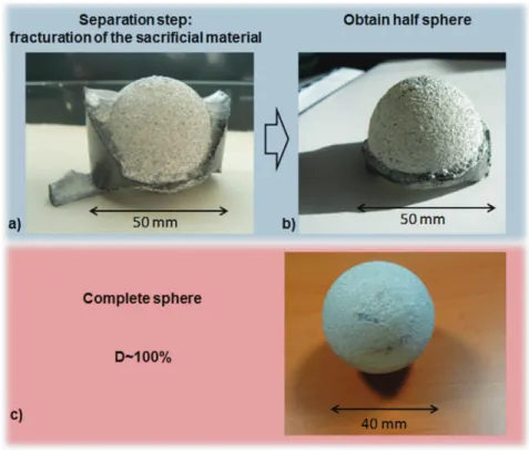
A 20 K/min temperature ramp up the 100 °C[11]is performed for the PMMA assembly densification. The separation step for the PMMA hemi-sphere is shownFig. 2a. The image indicates the cracks propaga-tion of the sacrificial area stopped at the contact with the BN layer, an area that remains at the powder state. Thus, the fracturing is limited to the sacrificial area. The separation is then easy and the final PMMA hemi-sphere was obtained (see Fig. 2b). The fracturing separation method is mandatory for the PMMA case because of the very coarse in-terface rugosity that hang a little bit the two parts together. The com-plete sphere was also tested with the same methodology and two half-ellipsoids was assembled to create a powder cylinder with an inter-nal ellipsoidal interface. The obtained sphere is presentedFig. 2c. Both sphere and hemi-sphere appear white on the photographs taken direct-ly after the fragmentations due to some remaining BN powder bonded to their surface (the BN powder at the separation interface is white). By observing the bottom face of the hemi-sphere and the aspect of the fractured parts, one can say that the two parts are fully dense, since the polymer is transparent (seeFig. 2a sacrificial fractured part). The densification measured by geometrical method confirms that point as the relative density of the two parts is close to 100%. This first group of experiments shows the predictability of the shape for a total densifi-cation. In the following section, the results for the graphite foils ap-proach are presented.
5.2. The graphite foil approach
The graphite foil approach was tested on different shapes reported inFig. 3. A 50 K/min temperature ramp up to 550 °C[40]is applied for the aluminum powder assembly densification and a further 100 K/min
1200 °C for the alumina/zirconia test. The overall densification is 99% for the cone and 97% for the pyramid and the star shapes. The interesting point of these experiments is that well-defined sharp edges are obtain-ed for both pyramidal and star shapes. This result is difficult to obtain by classical molding processes because the matter has often difficulties to fill corner edges. This problem is not present for the deformed interfaces method because the matter is present on both faces of the interface from the start. Nevertheless, a small deformation is noticeable for the star shape (Fig. 3c) precisely at the central point where all the lines
converged to the central point. In this point, the graphite foil thickness (0.2 mm) prevent a good definition of this part of the star shape and be-cause the graphite foil is manually deposited, some small distortions (shape rotated) are generated at the manual assembly stage.
Concerning the alumina/zirconia bi-material test, the result shows (Fig. 4) a well-defined cone shape with a relative density of 99% for the zirconia cone and 98% for the alumina sacrificial part. The microstructure of the cone is homogeneous as it is similar in the center and at the edge of the part with an average grain size of 0.4 ± 0.05 μm. This experiment
Fig. 2. a) Fracturing of the sacrificial material for the PMMA hemi-sphere, b) hemi-sphere after the separation step, c) full sphere PMMA specimen.
clearly shows that cost reduction is possible using a low price sacrificial material. Furthermore, it is demonstrated that ceramic parts can be obtained with complex geometry and with nano-structured microstructures.
5.3. High complex shape densification test
The previous tests proved the feasibility of the deformed interfaces method for the different material and more or less complex shapes. In this section, the shape is a turbine blade (seeFig. 5a). This highly com-plex shape possesses sharp edges, round and thin areas, right angles and high thickness variations from 2 mm to 30 mm. This shape gathers nearly all the main densification difficulties that can be encountered for the pressure assisted sintering of complex shapes. The graphite foil
approach is employed with the addition of a BN spray on the foil in order to prevent the carburation of the superalloy powder. A 100 K/min temperature ramp up to 900 °C[41]was applied for the CoNiCrAlY powder assembly densification. The spark plasma sintered turbine blade obtained is presented inFig. 5b. The shape is very closed to the target (Fig. 5a), the sharp edges, round and thin areas, right angles are very well defined and the overall densification of the part is 98% (Ar-chimedes' method).
Such as for the star shape (Fig. 3c), some slight discrepancies are ob-served on the wing shape and its location on the support. These differ-ences also originate from a problem of the graphite foil maintain during the assembly stage. In future purpose, to prevent the appearance of these discrepancies and at the same time simplify the methodology, it is possible to design specific supporting materials that help the placement
Fig. 4. Deformed interfaces method with two different materials: (top) zirconia cone and alumina sacrificial part, (bottom) SEM fractures surfaces of the cone at the center and the edge.
and maintain the shape of the graphite foil during the assembly stage. Nevertheless, this example shows a good densification for the very high complex shapes is then possible using the deformed interfaces method. 6. Conclusion
The ability of the deformed interfaces method to develop fully dense parts with highly complex shapes has been experimentally demonstrat-ed with different types of material. This method uses a sacrificial mate-rial to homogenize the displacement field allowing a total densification whatever the complexity of the shape of the part to be formed. This method can be applied to many sintering techniques such as HIP and HP but using this method with the SPS technology allows us to control the microstructure. It is technically possible to divide the internal inter-face in several shapes sintered simultaneously. This method presents then an advantage to improve the productivity of techniques such as HP, HIP or SPS. The main challenge of this method is to generate an as-sembly of powders separated by an internal interface that possesses a complex shape. Two approaches have been presented; the imprint and graphite foil approaches. Both these methods have demonstrated their ability to generate easily different shapes difficult to fabricate in the classical approaches. Finally, a fully-dense highly complex turbine blade has been fabricated using the graphite foil approach. This example gathers all the main positives characteristics of the method: the possi-bility to perform shapes with high thickness variations, well-defined sharp edges, round and thin areas and right angles.
Acknowledgments
The support of the Plateforme Nationale CNRS de Frittage Flash (PNF2/CNRS) is gratefully appreciated. C.M. and C.E. thank the French National Research Agency (ANR) for financial support of this study within project ANR09 MAPR-007 Impulsé.
References
[1] Z.A. Munir, U. Anselmi-Tamburini, M. Ohyanagi, The effect of electric field and pres-sure on the synthesis and consolidation of materials: a review of the spark plasma sintering method, J. Mater. Sci. 41 (2006) 763–777,http://dx.doi.org/10.1007/
s10853-006-6555-2.
[2] R. Orrù, R. Licheri, A.M. Locci, A. Cincotti, G. Cao, Consolidation/synthesis of materials by electric current activated/assisted sintering, Mater. Sci. Eng. R. Rep. 63 (2009) 127–287,http://dx.doi.org/10.1016/j.mser.2008.09.003.
[3] S. Grasso, Y. Sakka, G. Maizza, Electric current activated/assisted sintering (ECAS): a review of patents 1906–2008, Sci. Technol. Adv. Mater. 10 (2009), 053001.
http://dx.doi.org/10.1088/1468-6996/10/5/053001.
[4] O. Guillon, J. Gonzalez-Julian, B. Dargatz, T. Kessel, G. Schierning, J. Räthel, et al., Field-assisted sintering technology/spark plasma sintering: mechanisms, materials, and technology developments, Adv. Eng. Mater. 16 (2014) 830–849,http://dx.doi.
org/10.1002/adem.201300409.
[5] B.-N. Kim, K. Hiraga, K. Morita, H. Yoshida, Effects of heating rate on microstructure and transparency of spark-plasma-sintered alumina, J. Eur. Ceram. Soc. 29 (2009) 323–327,http://dx.doi.org/10.1016/j.jeurceramsoc.2008.03.015.
[6] M. Tokita, Industrial applications of advanced spark plasma sintering, Am. Ceram.
Soc. Bull. 85 (2006) 32–34.
[7] Website:http://www.fct-systeme.de/fr/content/Spark_Plasma_Sintertechnologie/ 2016.
[8] K. J. Micklash, M. S. Bailey, Hot pressing apparatus and method for same. US Patent No. US 2013/0140740 A1, (2013).
[9] J. Schmidt, A. Knote, M. Armbrüster, Th. Weißgärber, B. Kieback, Spark plasma
sintering of diamond impregnated wire saw beads, PM2010 World Congress – Diamond Tools, 2010.
[10] M. Suarez, A. Fernandez, J.L. Menendez, R. Torrecillas, H.U. Kessel, J. Hennicke, et al., Challenges and opportunities for spark plasma sintering: a key technology for a new generation of materials, Sintering Applications, 2013,http://dx.doi.org/10.5772/53706.
[11] C. Manière, PhD thesis of the University of Toulouse, Spark Plasma Sintering:
Model-ing, Device and Materials Approaches 2015, p. 175.
[12] K. Matsugi, H. Kuramoto, T. Hatayama, O. Yanagisawa, Temperature distribution at steady state under constant current discharge in spark sintering process of Ti and Al2O3powders, J. Mater. Process. Technol. 134 (2003) 225–232,http://dx.doi.org/
10.1016/s0924-0136(02)01039-7.
[13] A. Zavaliangos, J. Zhang, M. Krammer, J.R. Groza, Temperature evolution during field activated sintering, Mater. Sci. Eng. A 379 (2004) 218–228,http://dx.doi.org/10.
1016/j.msea.2004.01.052.
[14] K. Vanmeensel, A. Laptev, J. Hennicke, J. Vleugels, O. Vanderbiest, Modelling of the temperature distribution during field assisted sintering, Acta Mater. 53 (2005) 4379–4388,http://dx.doi.org/10.1016/j.actamat.2005.05.042.
[15] U. Anselmi-Tamburini, S. Gennari, J.E. Garay, Z.A. Munir, Fundamental investigations on the spark plasma sintering/synthesis process, Mater. Sci. Eng. A 394 (2005) 139–148,http://dx.doi.org/10.1016/j.msea.2004.11.019.
[16] G. Molénat, L. Durand, J. Galy, A. Couret, Temperature control in spark plasma sintering: an FEM approach, J. Metall. 2010 (2010) 1–9,http://dx.doi.org/10.1155/
2010/145431.
[17] A. Pavia, L. Durand, F. Ajustron, V. Bley, G. Chevallier, A. Peigney, C. Estournès, Electro-thermal measurements and finite element method simulations of a spark plasma sintering device, J. Mater. Process. Technol. 213 (2013) 1327–1336,http://
dx.doi.org/10.1016/j.jmatprotec.2013.02.003.
[18] J.B. Allen, C. Walter, Numerical simulation of the temperature and stress field D evo-lution applied to the field assisted sintering technique, ISRN Mater. Sci. 2012 (2012)
1–9,http://dx.doi.org/10.5402/2012/698158.
[19] C. Maniere, A. Pavia, L. Durand, G. Chevallier, V. Bley, K. Afanga, A. Peigney, C. Estournès, Pulse analysis and electric contact measurements in spark plasma sintering, Electr. Power Syst. Res. 127 (2015) 307–313,http://dx.doi.org/10.1016/j.
epsr.2015.06.009.
[20] C. Manière, A. Pavia, L. Durand, G. Chevallier, K. Afanga, C. Estournès, Finite-element modeling of the electro-thermal contacts in the spark plasma sintering process, J. Eur. Ceram. Soc. (2015),http://dx.doi.org/10.1016/j.jeurceramsoc.2015.10.033. [21] C. Arnaud, C. Manière, G. Chevallier, C. Estournès, R. Mainguy, F. Lecouturier, et al.,
Dog-bone copper specimens prepared by one-step spark plasma sintering, J. Mater. Sci. 50 (2015) 7364–7373,http://dx.doi.org/10.1007/s10853-015-9293-5. [22] D. Giuntini, E. Olevsky, C. Garcia-Cardona, A. Maximenko, M. Yurlova, C. Haines, et al.,
Localized overheating phenomena and optimization of spark-plasma sintering tooling design, Materials 6 (2013) 2612–2632,http://dx.doi.org/10.3390/ma6072612. [23] E.A. Olevsky, Theory of sintering: from discrete to continuum, Mater. Sci. Eng. R. Rep.
23 (1998) 41–100,http://dx.doi.org/10.1016/s0927-796x(98)00009-6.
[24] G. Maizza, S. Grasso, Y. Sakka, Moving finite-element mesh model for aiding spark plasma sintering in current control mode of pure ultrafine WC powder, J. Mater. Sci. 44 (2009) 1219–1236,http://dx.doi.org/10.1007/s10853-008-3179-8.
[25]M. Abouaf, (PhD thesis) Modelisation de la compaction de poudres métalliques
frittées. Approche par la mécanique des milieux continus. Institut national polytechnique de Grenoble, 1985.
[26] M. Abouaf, J.L. Chenot, G. Raisson, P. Bauduin, Finite element simulation of hot
iso-static pressing of metal powders, Int. J. Numer. Methods Eng. 25 (1988) 191–212. [27] C. Geindreau, D. Bouvard, P. Doremus, Constitutive behaviour of metal powder
dur-ing hot formdur-ing. Part I: experimental investigation with lead powder as a simulation material, Eur. J. Mech. A. Solids 18 (1999) 581–596,http://dx.doi.org/10.1016/
s0997-7538(99)00102-3.
[28] C. Geindreau, D. Bouvard, P. Doremus, Constitutive behaviour of metal powder dur-ing hot formdur-ing, Eur. J. Mech. A. Solids 18 (1999) 597–615,http://dx.doi.org/10.
1016/s0997-7538(99)00101-1.
[29] E.A. Olevsky, C. Garcia-Cardona, W.L. Bradbury, C.D. Haines, D.G. Martin, D. Kapoor, Fundamental aspects of spark plasma sintering: II. Finite element analysis of scalability, J. Am. Ceram. Soc. 95 (2012) 2414–2422,http://dx.doi.org/10.1111/j.
1551-2916.2012.05096.x.
[30] C. Manière, L. Durand, A. Weibel, C. Estournès, Spark-plasma-sintering and finite el-ement method: from the identification of the sintering parameters of a submicronic α-alumina powder to the development of complex shapes, Acta Mater. 102 (2016) 169–175,http://dx.doi.org/10.1016/j.actamat.2015.09.003.
[31] H. Kim, O. Gilla, P. Dorémus, D. Bouvard, Near net shape processing of a sintered
alu-mina component: adjustment of pressing parameters through finite element simu-lation, Int. J. Mech. Sci. 44 (2002) 2523–2539.
[32]A. Frachon, (PhD thesis) Modélisation et Simulation Numérique de la Compression en
Matrice de Poudres Métalliques. Institut National Polytechnique de Grenoble, 2002.
[33] G.S. Wagle, (PhD thesis) Die Compaction Simulation: Simplifying the Application of
a Complex Constitutive Model Using Numerical and Physical Experiments. The Pennsylvania State University, 2006.
[34] D. Giuntini, J. Raethel, M. Herrmann, A. Michaelis, E.A. Olevsky, Advancement of tooling for spark plasma sintering, J. Am. Ceram. Soc. 98 (2015) 3529–3537,
http://dx.doi.org/10.1111/jace.13528.
[35] T. Voisin, J.-P. Monchoux, L. Durand, N. Karnatak, M. Thomas, A. Couret, An innova-tive way to produce γ-TiAl blades: spark plasma sintering, Adv. Eng. Mater. 17 (2015) 1408–1413,http://dx.doi.org/10.1002/adem.201500019.
[36] C. Manière, L. Durand, A. Weibel, G. Chevallier, C. Estournès, A sacrificial material ap-proach for spark plasma sintering of complex shapes, Scr. Mater. 124 (2016) 126–128,http://dx.doi.org/10.1016/j.scriptamat.2016.07.006.
[37] P. Mondalek, L. Silva, M. Bellet, A numerical model for powder densification by SPS technique, Adv. Eng. Mater. 13 (2011) 587–593,http://dx.doi.org/10.1002/adem.
201000340.
[38] D. Chakravarty, G. Sundararajan, Microstructure, mechanical properties and ma-chining performance of spark plasma sintered Al2O3–ZrO2–TiCN nanocomposites,
J. Eur. Ceram. Soc. 33 (2013) 2597–2607,http://dx.doi.org/10.1016/j.jeurceramsoc.
2013.04.021.
[39] C. Estournès, C. Manière, L. Durand, French Patent number FR1560654 deposited the 04/11/2015.
[40] R.W. Cooke, N.P. Kraus, D.P. Bishop, Spark plasma sintering of aluminum powders prealloyed with scandium additions, Mater. Sci. Eng. A 657 (2016) 71–81,http://dx.doi.org/10.1016/j.msea.2016.01.053.
[41] S. Todde, R. Licheri, R. Orrù, G. Cao, Spark plasma sintering processing for the evaluation of cryomilled CoNiCrAlY alloys for high temperature applications in oxidizing environ-ment, Chem. Eng. J. 200 (2012) 68–80,http://dx.doi.org/10.1016/j.cej.2012.06.009.