Responsive Nano
fibers with Embedded Hierarchical Lipid
Self-Assemblies
Nguyen D. Tien, Anjani K. Maurya, Giuseppino Fortunato, Markus Rottmar, Robert Zboray, Rolf Erni,
Alex Dommann, René M. Rossi, Antonia Neels, and Amin Sadeghpour
*
ABSTRACT: We introduce the design and study of a hybrid electrospun membrane
with a dedicated nanoscale structural hierarchy for controlled functions in the biomedical domain. The hybrid system comprises submicrometer-sized internally self-assembled lipid nanoparticles (ISAsomes or mesosomes) embedded into the electrospun membrane with a nanofibrous polymer network. The internal structure of ISAsomes, studied by small-angle X-ray scattering (SAXS) and electron microscopy, demonstrated a spontaneous response to variations in the environmental conditions as they undergo a bicontinuous inverse cubic phase (cubosomes) in solution to a crystalline lamellar phase in the polymer membrane; nevertheless, this phase reorganization is reversible. As revealed by in situ SAXS measurements, if the membrane was put in contact with aqueous media, the cubic phase reappeared and submicrometer-sized cubosomes were released upon dissolution of the nanofibers. Furthermore, the hybrid membranes exhibited a specific anisotropic feature and
morphological response under an external strain. While nanofibers were aligned under external strain in the microscale, the semicrystalline domains from the polymer phase were positioned perpendicular to the lamellae of the lipid phase in the nanoscale. The fabricated membranes and their spontaneous responses offer new strategies for the development of structure-controlled functions in electrospun nanofibers for biomedical applications, such as drug delivery or controlled interactions with biointerfaces.
■
INTRODUCTIONElectrospinning is an effective technique to produce porous fibrous membranes using an electrostatically driven jet of a polymer solution.1−4 The functional properties of these membranes are controlled by the chemical nature of electrospinning materials,5 application of different processing strategies,6,7 or encapsulation of bioactive agents.8,9 The polymer type, molecular weight, its concentration, and the physical conditions of the electrospinning environment, e.g., temperature and relative humidity, are normally applied for controlling the fiber morphology and respective biomedical functions in tissue engineering and drug delivery applica-tions.10−13
Moreover, various macromolecular systems such as proteins and biopolymers have been used to design electrospunfibers that can mimic the structural features of an extracellular matrix for controlled cell growth and nutrients transport.14−16 Therefore, controlling the multiscale hierarchy in nanofibers can offer specific functions for emerging applications in biomedicine or biotechnology. For instance, it has been demonstrated that an alignedfibrous structure can be exploited to guide stem cell differentiation in annulus fibrosis tissue engineering.17 Also, different morphologies and sizes of nanofibers as well as their surface properties are known to play important roles in controlling basic cellular processes as
well as cell fate decisions.18−20In terms of the nanostructural investigation, a combination of small- and wide-angle X-ray scattering (SAXS/WAXS) and advanced imaging technologies has been widely used to elucidate the nanofiber morphology including fibrillar spacing, orientation degree, molecular arrangement, and crystallinity of nanofibers in the native state.21−24
Recently, most strategies in designing nanofibers have been focused on the synergistic effects from different classes of materials to deliver controlled functions and enhanced biocompatibility. Through electrospinning, nanoparticles of different size and shape can be incorporated into the interior or on the surface of nanofibers, leading to formation of hybrid systems with promising functions as sensing materials, semipermeablefilms, and antibacterial membranes.25−27
Among those hybrid nanofibers, incorporation of lipid-based nanoparticles into polymer systems is emerging.28,29 The internally self-assembled lipid nanoparticles (ISAsomes)
http://doc.rero.ch
Published in "Langmuir 36(40): 11787–11797, 2020"
which should be cited to refer to this work.
provide new possibilities for nanoscale hierarchical design and control of the structural hierarchy. ISAsomes (also called mesosomes) are submicrometer-sized particles and consist of a liquid crystalline phase at their interior like inverse bicontinuous cubic (cubosomes), inverse hexagonal (hexo-somes), or inverse micellar cubic phases.30,31These phases are spontaneously formed with lipids like glycerol monooleate or phytantriol in excess water at ambient temperature. Nonionic surfactants, e.g., pluronic block copolymers, or Pickering stabilizers such as silica nanoparticles can be used to disperse them.32−35Among the different lipid particles, the cubosomes have drawn attention due to their unique functional properties. Their internal cubic phase consists of two intertwined water channels a few nanometers wide, separated by cellular mimicking lipid bilayers with a hydrophobic core. Such a unique hierarchy offers advantages to load drugs with hydrophilic/hydrophobic moieties and controls their delivery through structural responses.36−39The structure of the cubic phase can be altered by changing various parameters through experimental conditions. A thin monooleate-based dryfilm has demonstrated a lamellar to cubic phase transition using time-resolved grazing-incidence small-angle X-ray scattering (GI-SAXS) when gradually exposed to humidity.40 Pressure-induced structural transitions have been concluded by pressure-jump time-resolved SAXS, demonstrating lamellar− cubic41 and cubic−cubic transitions42,43 at fixed hydration. The lipid composition can also be used to induce phase transitions. In a mixture with two types of ISAsomes with different internal lipid compositions, the lipid exchange between the particles led to the evolution of an intermediate internal structure.44Similar studies were applied for the hybrid systems containing the ISAsome mixture in a biopolymer solution. Likewise, evolution of the intermediate structure was observed but with a slower dynamic behavior; thereby, their entrapment into the network of the biopolymer gel reduced the rate of lipid exchange between the ISAsomes.45,46To the best of our knowledge, recent work by Hai et al.47is the only study so far on the hybrid lipid−polymer system with electrospun nanofibers. They reported on the lipid-coated polymer fibers by modified coaxial electrospinning. However, their study was focused on the fabrication of a detachable concentric spinneret without any detailed nanostructural investigations.
In this study, we introduce the design of a new responsive nanofiber membrane with internally self-assembled lipid mesosomes and its comprehensive characterization. Our strategy relies on the successful incorporation of cubosomes into a polymer solution, identifying appropriate conditions for electrospinning, unveiling the lamellar hierarchy in the nanofiber membranes, and eventually retrieving cubosomes upon dissolution of the nanofiber membranes in aqueous solution. With a change in the relative humidity or an applied external mechanical strain, the internal nanostructures in the membranes can be well controlled. As a result, our responsive membranes open up new possibilities in the design of a soft medical device such as a biodegradable drug nanocarrier for wound-healing patches or smart coatings for implants.
■
MATERIALS AND METHODSCubosomes Preparation. The nanostructured lipid particle dispersions, i.e., cubosomes, were prepared from glycerol monooleate (GMO), supplied by DANISCO (Brabrand, Denmark), under the commercial name Dimodan U/J, in excess water. Pluronic F127, an
amphiphilic triblock copolymer of poly(ethylene oxide) and poly-(propylene oxide), i.e., PEO99−PPO67−PEO99, was obtained from
Sigma-Aldrich. In all experiments, about 10 g of aqueous dispersions was prepared in which 10 wt % of Dimodan U/J and 1 wt % of F127 were used. All of the solutions were prepared using Milli-Q water (resistivity at 25 °C 18.2 MΩ·cm, Sigma-Aldrich). Mixtures of Dimodan U/J and F127 in water were emulsified by tip ultra-sonication (Branson Digital Sonifier, USA) at 70% power in pulse mode (2 s pulses with 1 s pause) for 3 min resulting in a homogeneous, milky dispersion. The samples were then sealed and left to equilibrate at room temperature for about 2 h before mixing with the polymer solution. Further details about cubosomes preparation can be found elsewhere.45 The average size of the
dispersed cubosomes was measured as 180± 20 nm by dynamic light scattering (Nicomp 380).
Polymer Spinning Solutions and Electrospun Fibers with Embedded Lipid Mesosomes. Poly(ethylene oxide) (PEO) with a molecular weight (Mw) of 300 000 g/mol was purchased from
Sigma-Aldrich and dissolved in Milli-Q water to yield solutions with concentrations of 5, 6, and 10 wt %. The solutions were mixed with cubosome dispersions at different weight ratios using a vortex mixer (VWR Switzerland) at 2500 rpm in 30 min to end up at determined concentrations in the mixtures. Hereafter, the PEO/lipid ratio is referred to as the ratio in weight (w/w). A custom-built electro-spinning setup consisting of an infusion pump (KD Scientific, USA) with a steadyflow of solutions was used. The solutions were filled in a 1 mL syringe tipped with a 21 G blunt needle (outer diameter of 0.82 mm). Experiments were performed at aflow rate of 5 μL/min for all solutions with applied voltages of +10 kV on the needle and−5 kV on the counter electrode. A tip-to-collector distance of 15 cm was applied. All solutions were processed intofibers at 24 °C and 20% relative humidity if not specified otherwise.
Rheology Measurement. A rheometer (Anton Paar Physica MCR 300, Austria) equipped with a plate and cone system was used to study the rheological properties of the cubosome−polymer mixture. To exclude the aging of solutions, a preshearing of 50 s−1 was applied for 30 s at 20°C before measurements. Flow curves with shear rates varying from 0.01 to 500 s−1 were recorded at 20°C in triplicate. The results are shown inFigure S3.
Scanning Electron Microscopy (SEM). Fiber surface morphol-ogy was investigated by SEM (Hitachi S-4800, Hitachi High-Technologies, USA) using a 2 kV accelerating voltage and 10 mA beam current. The samples were mounted on metal stubs before observation and sputter coated with gold/palladium of 8 nm thickness to increase the electrical conductivity. The mean diameters and their distributions were calculated based on measurements of 50 fibers from the SEM micrographs using ImageJ software (NIH, USA).
Transmission Electron Microscopy (TEM). TEM was carried out using a JEOL 2200 fs operated at 200 kV. Aside from room temperature, measurements were also performed at liquid nitrogen temperature using a cryo TEM holder from JEOL (model EM-31660). Images were collected using a Gatan US1000 CCD camera. TEM samples were prepared by electrospinning directly on carbon-coated TEM grids for 60 s.
Small-Angle X-ray Scattering (SAXS). The nanoscale structures have been determined by SAXS using a Nanostar instrument (Bruker, Germany). The instrument is equipped with Cu Kα radiation (wavelength,λ, 1.5406 Å) and a VÅNTEC-2000 detector positioned at a sample to detector distance (SDD) of about 67 cm. This setup provides scattering vector magnitudes of 0.09−3.2 nm−1and benefits
from a custom-built semitransparent beamstop for enhanced resolution and precise background subtraction. The magnitude of the scattering vector, q, is defined by q = (4π/λ)sin(θ/2), where θ is the scattering angle and calibrated using silver behenate having a d spacing of 5.8380 nm.48All of the experiments have been performed
at room temperature with exposure times of 3600 and 600 s for the solution andfiber samples, respectively. Before the measurement, the precise sample position was identified by two-dimensional (2D) nanography. In nanography, the capillary was scanned along the X and Y axes with a spatial resolution of 0.1 μm. The transmitted signal
intensity is measured for each X and Y coordinate to identify the exact position of the sample.49 Capillaries of 1.5 mm (Hilgenberg, Germany) were used for solution sample analysis. For time-resolved humidity measurement, a dedicated setup was designed to monitor the structural changes of the lipid−polymer nanofibers. The schematic representation of the setup is shown in Figure S6. To fit the membrane into capillary tubes, we rolled the nanofiber membranes into a cylindrical shape that was approximately 1.5 mm in diameter and 10 mm in length and then transferred it into the measurement capillary of the flow cell setup. A 2 mm diameter quartz capillary (Hilgenberg, Germany) was connected to the water vaporizer on one side and the humidity sensor on the other side of the outlet. PTFE tubing was used to connect the water vaporizing cell to the measurement capillary. The temperature of the water container was set at 80°C. We recorded the frames of 120 s duration consecutively until we resolved all of the structural transitions. The 2D scattering frames were radially integrated to represent the scattering intensity I(q) as a function of scattering vector (q) in the 1D profiles.
Confocal Laser Scanning Microscopy (CLSM). CLSM (LSM780, Carl Zeiss AG, Switzerland) images were taken to assess the lipid mesosomes within thefibers. To label the lipid mesosomes, fluorescein sodium salt (FNa, Mw= 376 g/mol, Sigma-Aldrich) was
loaded at 0.1 wt % into the mesosome system. Thefibers containing mesosomes with FNa were prepared directly on glass slides for further observation at 20× magnification and an excitation wavelength of 488 nm.
X-ray Nanocomputed Tomography (nano-CT). For X-ray nano-CT, we used an EasyTom XL Ultra 230-160 micro/nano-CT scanner (Rx Solutions SAS, Chavanod, France). The scanner features a Hamamatsu nanofocus, transmission X-ray tube with a 1 mm thick tungsten target on a diamond window. The tube was operated with a LaB6 cathode. The scans were performed using a Varian PaxScan 2520DX detector (flat panel with amorphous silicon and a CsI conversion screen; 1920× 1536 pixel matrix; pixel pitch of 127 mm; 16 bits of dynamic range). The tube was operated at 70 kV and a current of 30 mA. The voxel size of the CT scans varied between 0.4 and 0.6μm. The images were acquired at one frame per second and averaged over 40 frames per projection.
■
RESULTS AND DISCUSSIONInteractions of Cubosomes with PEO in Solution. The appropriate choice of polymer as well as the processing approach in our studied hybrid systems are crucial to ensure preservation of the lipid hierarchy. Therefore, a detailed understanding of cubosome interactions with the polymer in an aqueous solution is required. In particular, polymers’
hydrophilicity and charging behavior are shown to play an important role in the stability of lipid particles like cubosomes.45,46,50 In the cubosomes stabilized by F127 triblock copolymer (PEO-PPO-PEO, see the Materials and Methodsfor more details) the hydrophilic PEO chains face the aqueous medium.51 Therefore, we hypothesize that PEO would be compatible with the cubosomes coated with the PEO-based block copolymers. To elucidate the stability and fine structural variation of the cubosomes, we investigated the interactions between them and the polymers at different concentrations quantitatively. Cubosomes and PEO solutions were mixed with varying concentrations (ranging between 0 and 5 wt %). All concentrations are converted to PEO/lipid ratios as shown inFigure 1. The SAXS profiles demonstrate a cubic phase signature for all cubosome-added samples (see
Figure 1A).
Lipid-based cubosome particles of 180± 20 nm (measured by DLS) were studied as pure or in a mixture with PEO in solution. In Figure 1A, all studied samples (apart from pure PEO, labeled as PEO/lipid = 1:0) demonstrate three discernible small-angle X-ray diffraction peaks. These dif-fractions at q110= 0.69 nm−1, q200= 0.97 nm−1, and q211= 1.19
nm−1 are attributed to the Im3̅m bicontinuous cubic phase with relative peak positions of √2:√4:√6.52,53 In contrast, PEO as a water-soluble polymer demonstrates a monotonic decay in the scattering intensity. Notably, the diffraction peaks from the cubic phase are present even at relatively high PEO to lipid ratio (10:1), and only small changes in peak positions could be identified. More detailed analysis indicates that the peaks shift slightly to smaller q positions by increasing the PEO concentration (e.g., the 110 reflection shifts from 0.687 ± 0.001 nm−1 in the pure cubosome system to 0.649 ± 0.001 nm−1 for 50% PEO containing mixture). This demonstrates the lattice expansion in the cubic structure (from 12.93± 0.02 to 13.69 ± 0.02 nm). The calculated lattice parameters for different systems with varying PEO to lipid ratios are shown in
Figure 1B (details of this calculation are presented in the
Supporting Information). It is noted that swollen lipidic bicontinuous cubic phases have been observed and tailored by different approaches such as inducing electrostatic repulsion between lipid bilayers by adding charged lipids54−56or altering the curvature at the bilayer−water interface by adding
Figure 1. Structural study of cubosomes upon interaction with PEO at different weight ratios in solution: (A) 1D-SAXS profiles and (B) cubic lattice parameters calculated from the diffraction peaks and its relative change with respect to cubic lattice from pure cubosomes.
cholesterol.55,57 Here, we observe about 6% swelling in the primitive cubic phase lattice parameter in the mixture with the polymer. This striking phenomenon is explained by the change in the interfacial curvature of cubic phase bilayers toward less negative values (closer to zero curvature)51in the presence of PEO or by the lipids’ critical packing parameter (CPP). The CPP is a quantitative description of molecular shape which indicates the volume ratio of the hydrophobic to hydrophilic parts of an amphiphilic molecule.58 For instance, monoolein has a CPP value greater than unity, while phospholipids’ CPP equals unity. The change in interfacial curvature suggests that the PEO behaves like a hydration-modulating agent which promotes hydration of lipid head groups and reduces the lipids’ critical packing parameter to a value closer to unity. This leads to an expansion of the water channels in the Im3̅m phase and an increase in its lattice parameter. Similar curvature modification has been reported previously for monoolein-based systems upon interactions with polymer PP50.59 It is noteworthy that expansion of the cubic phase occurs mainly up to a polymer to lipid ratio of around 2 (w/w), and beyond that, the lattice parameter only changes slightly, suggesting a saturation in the hydrating effect of PEO. Apart from this swelling behavior, the stability of the Im3̅m phase was confirmed throughout the whole studied PEO to lipid ratios. We also investigated the influence of higher molecular weight PEO, i.e., 1 000 000 g/mol, and observed similar behavior (data not shown). Therefore, before electrospinning, we ensured that the Im3̅m symmetry is preserved in cubosomes in its mixture with PEO.
Electrospun Fibers with Embedded Lipid Meso-somes. The prepared cubosomes appeared as a milky dispersion with low viscosity, making it impossible to spin. In contrast, the use of PEO increased the viscosity of the mixture by entrapment of lipid particles into the entangled polymer network. This concept conveys our strategy to increase the viscosity of the dispersion and achieve a spinnable condition for the cubosome−polymer mixture. However, finding appropriate conditions in which this mixture could
be transformed into a highly entangled and uniform fibrous structure by electrospinning was very challenging. Therefore, various parameters in the processing setup and the solution preparations, such as concentrations of materials, surface tension, and viscoelasticity of solutions,60 had to be considered. By use of the 300 000 g/mol molecular weight and 5 wt % PEO solution, a uniformfiber structure with fiber diameters of around 120−180 nm could be obtained. In agreement with previous studies,2,61 our investigations demonstrated an increase in thefiber diameter with increasing concentration of PEO solution and its viscosity (Figure S2). Electrospinning of 5 wt % PEO solution led to nanofibers with an average diameter of 154 ± 28 nm. For 6 and 10 wt % solutions, the average nanofiber diameter increased to 233 ± 33 and 399 ± 53 nm, respectively. According to this evaluation, we identified an optimum PEO concentration of 5 wt % from which a submicrometer-sizedfibers network and a narrow fiber diameter distribution (width at half-maximum of 28 nm) were obtained. The viscosity was also increased for the 5 wt % PEO mixed with increasing amounts of lipid cubosomes. The 5:5 (% w/w) PEO/lipid mixture (shown as the 1:1 weight ratio inFigure S3) demonstrated the highest viscosity and good input solution properties for electrospinning. Further increase of the lipid cubosome content, i.e., PEO/lipid < 1, resulted in solutions that caused an unstable jet during electrospinning, and nofibrous network was formed. Therefore, we select the mixture solutions containing 5 wt % PEO and 0−5 wt % lipid cubosome concentration for electrospinning.
The influence of environmental parameters in electro-spinning, i.e., the relative humidity, was studied to select an appropriate condition for the fabrication of membranes. As the relative humidity increases, the solvent evaporation is reduced during the time-of-flight. This leads to smaller drag forces imposed on polymerfibers, further elongation of the charged jet, and thus formation of thinner fibers.6,62,63Therefore, we observed a decrease in the average diameter of pure PEO nanofibers with an increase in the relative humidity from 20%
Figure 2. (A) Schematic representation of the electrospinning setup, and (B) photograph of the obtained hybrid polymer−lipid membranes. (C) Demonstration of a quantitative analysis of SEM images resulting in the averagefiber diameter for membranes with varying PEO/lipid ratios at different relative humidity. (D−F) SEM images show the influence of environmental humidity on the fiber morphology and beads formation in the PEO/lipid samples of a 5:5 (% w/w).
to 60% (seeFigure 2C). By embedding the lipid particles, the average nanofiber diameter was increased at all of the humidity conditions. However, it was found that the beads can also be formed under higher humidity conditions.Figure 2E is a SEM image of a membrane with the 5:5 (% w/w) PEO/lipid prepared under around 40% relative humidity which indicates beads formation. The beads are more populated for a membrane with the same PEO/lipid content but prepared at 60% relative humidity, as shown in Figure 2F. Therefore, we selected 20% relative humidity to proceed for the fabrication of bead-free andfine structural analysis of nanofiber membranes (Figure 2D).
Under the above-optimized conditions, we tailored the lipid cubosome concentration at 5 wt % (ultimate PEO to lipid ratio of 1), which allowed detection of a distinct signal in SAXS to assess the nanostructural arrangement of lipid mesosomes.
Figure 3 shows the SAXS profiles of electrospun membranes
prepared at various PEO/lipid ratios. Unlike the set of three diffraction peaks in solution, we observe a diffraction peak at q = 1.29 nm−1, starting to display at the PEO/lipid ratio of 5:1 and continuing to increase in intensity by increasing the lipid content. This indicates that the inverse bicontinuous cubic phase reorganizes into a different symmetry upon electro-spinning. We attribute this single peak to the reflection from the planar arrangement of monoolein molecules as a crystalline multilamellar gel phase, in agreement with the previous work on the dry-castedfilm of monoolein which reports a lamellar peak at 1.2 nm−1. The small discrepancies may originate from a different hydration level of lipid molecules in our hybrid nanofiber sample compared to their casted film.40The lamellar assembly demonstrates a d spacing of 4.87 nm, calculated by Bragg’s law of 2π/q. This interpretation is confirmed by revisiting the phase diagram for the monoolein system at very low water content64,65 where the lipid molecules take a reduced chain splay. This leads to a change in their molecular
shape (reducing the CPP of the molecule) and hence the change in the curvature of the whole lipid−water interface. This can continue until lipid molecules take a critical packing parameter of ∼1, where the self-assembly is complete in a crystalline lamellar phase.66 Interestingly, the lamellar phase with a 5.20 nm spacing has been previously reported for a monoolein system at high pressure (1100 bar), which, like the low water condition, induces a reduction in the lipid chain splay and imposes a critical packing parameter close to unity.67 Therefore, we verified a phase reorganization from cubic to lamellar by electrospinning of the mesosome−polymer mixture. This striking observation in PEO−lipid nanofibers suggests a possible reverse response of nanofibers upon rehydration, which is discussed later.
The observation of a broad hump at around 2.1 nm−1 (indicated by q′ inFigure 3) is very similar to the peaks from monoolein-based systems reported previously at 1.9 and 2.0 nm−1 (for the films dried from ethanol and chloroform, respectively) and attributed to the sponge (L3) phase.40,68 Moreover, the phase diagram of a pure monoolein confirms the full formation of a sponge phase at water contents beyond 20%.64This boundary condition is the same relative humidity that we used during the fabrication of our electrospun membranes; however, the ultimate water content can be different as it is shown to be also dependent on the hydrophilicity of the system.69 Therefore, in our hybrid membranes made of a hydrophilic polymer and incorporated with a water-containing lyotropic phase, a coexistence of L3 sponge phase is very likely. Also, we know that the sponge phase bears an interfacial curvature that is slightly negative but not lower than the one for the Im3̅m phase. Accordingly, it can appear as a transition phase between Im3̅m cubic and pure lamellar self-assembly. The scattering profiles also show broad peaks at 0.32 and 0.64 nm−1(indicated by q1*and q2*inFigure
3). These peaks at very small q positions can be attributed to the correlations between semicrystalline domains (lamellar sheets) with a spacing of about 19.5 nm. Such structural features by SAXS have been shown for poly(vinylidene fluoride-co-hexafluoropropylene) (PVDF-hfp) membranes pre-viously.24 Notably, such long-range orders could not be identified by diffraction from pure PEO fibers (the red curve in Figure 3). Therefore, it can be assumed that the PEO structure at the nanoscale is modified upon interaction with lipid nanoparticles, and the several nanometer range semi-crystalline domains are pronounced. Further studies are required to verify this interesting observation.
In addition to the SAXS results, a combination of methods has been applied to visualize the lipid mesosomes embedded into membranes and their microstructures. The results are summarized in Figure 4. SEM images (Figure 4A and 4B) illustrate the morphological appearance of the as-spun fibers obtained from pure PEO and PEO/lipid hybrid membranes, respectively. Formation offine fibers could be confirmed, and the average diameters were evaluated by SEM image analysis using the ImageJ software.70While the PEO concentration in the electrospinning solutions was kept constant at 5 wt %, we obtained average diameters of 162± 26 and 321 ± 34 nm for pure PEO and PEO/lipid (1:1) nanofibers, respectively (see alsoFigure S4for detailed information). It is noteworthy that this morphological difference between membranes of the pure polymer and hybrid ones is acquired despite the identical conditions being applied in the electrospinning setup. We attribute the larger fiber diameter in hybrid systems to the
Figure 3. X-ray scattering profiles of electrospun membranes with embedded lipid mesosomes at various PEO/lipid weight ratios. Identifiable diffraction peaks of the lamellar domain from PEO are assigned by q*1and q*2, whilefirst reflection from the lipid lamellar
phase is indexed with its corresponding Miller indices (100). Peak which is proposed to be originated from the sponge phase is shown by q′.
higher viscosity of their electrospinning mixture if compared with pure PEO at the same concentration (data are shown in
Figure S3). This is in agreement with previous reports about the influence of viscosity on the size of electrospun nanofibers.12,61Furthermore, the SEM images show a different morphological feature at the nanofiber junctions of hybrid. As shown inFigure 4B, welding occurs at the junctions of PEO/ lipid nanofibers. This may indicate that lipid mesosomes promoted interfiber connections. This will possibly lead to altered mechanical stability for the hybrid fiber membranes compared to pure PEO polymer membranes.71,72 To obtain further insights into mesosome incorporation into the fiber network, we conducted confocal laser scanning microscopy (CLSM). As shown in the inset ofFigure 4B, thefluorescein distribution demonstrates the pattern of nanofibers within the membrane. The signal can originate from encapsulated molecules within the cubosomes or from the molecules decorated on polymer fibers. In order to provide a detailed view of the incorporation of lipid particles within electrospun membranes, a TEM study was conducted. While nanofibers of pure PEO show a uniformfiber thickness in TEM (Figure 4C), the 100−200 nm size of the mesosome particles is shown to be entrapped within a single nanofiber in the hybrid system (Figure 4D). This verifies the mesosomes encapsulation inside the nanofibers, in agreement with the CLSM observation. Nonetheless, we note that the absorption of lipid particles at the surface of the nanofibers could not be excluded (see the patchyfibrous structure inFigure 4B).
To investigate the membranes’ structures in the micrometer scale, the X-ray CT technique was applied. Reconstructed 3D images for polymer and lipid/polymer hybrid membranes are shown inFigure 4E and4F. A qualitative comparison of these images demonstrates the morphological variations by the embedding of lipid particles into membranes. Indeed, the PEO/lipid membrane showed a porous structure, whereas the pores were not present in the pure PEO membrane. Such lipid-induced porosity can offer new possibilities in designing new functional membranes like 3D-electrospun scaffolds for tissue engineering purposes. We also performed FTIR to verify the
presence of lipid molecules in the membranes, which was indicated by a peak at 1731 cm−1assigned to vibration of C O of monoolein (seeFigure S5).
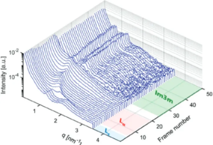
Retrievable Cubic Phase upon Water Intake. Despite the cubic phase disappearance after electrospinning, we demonstrated that hierarchical structures of lipids had not been destroyed but had undergone a phase reorganization into a planar structure. As discussed earlier, we attribute this observation to the phase behavior of the monoolein system under low water conditions rather than the influence of spin-processing itself. With this in mind, we anticipated that the cubic phase must be retrieved given that sufficient water vapor is taken up by the nanofiber system. We examined this hypothesis with an in situ humidity-SAXS measurement to visualize a sequence of structural transformation during water vapor uptake. The change in structures was recorded as a function of time every 2 min. A mechanistic understanding of phase reorganization could be achieved. The time-resolved profiles are shown in Figure 5. More details of the measurement are provided in the Methods and Materials, and a schematic representation of the setup is given inFigure S6.
The time-resolved scattering profiles show that shortly after exposure to water vapor and after four frames, the diffraction peak from the lamellar phase and the broad peak from the sponge phase at q = 1.29 and 2.10 nm−1turned into a single peak at q = 1.52 nm−1. This can be explained by the transformation of a crystalline lamellar (Lc) phase into afluid lamellar phase (Lα) with a smaller d spacing of 4.13 nm. The reduction in d spacing is a common observation for transitions from gel tofluid phases.73This single peak then shifted toward lower q values upon further water vapor absorption until q = 1.00 nm−1(equivalent to a d-spacing value of 6.20 nm) after 20 frames. This increase in d spacing can be explained by the development of water layers between lipid bilayers. Afterward, this single peak started to disappear and the scattering profiles displayed a transition state over the next 10 successive frames. Thereafter, a new set of peaks was displayed at q = 0.73, 1.04, and 1.31 nm−1. This scattering behavior demonstrates gradual
Figure 4. (A, B) SEM images of electrospun nanofiber membranes fabricated from pure PEO and PEO/lipid (1:1) mixtures in water. (Inset in B) Microscale CLSM image of the PEO/lipid hybrid membranes. Green color along thefibers demonstrates the fluorescein sodium salt distribution initially loaded into lipid mesosomes. (C, D) TEM images of a single PEO nanofiber and a nanofiber with embedded lipid mesosomes. (E and F) Reconstructed cross-sectional planes from X-ray nano-CT visualizing the internal microscale morphology in membranes fabricated by electrospinning of pure PEO and PEO/lipid hybrid systems, respectively. Mesosome-loaded sample demonstrates a microscale porosity.
phase rearrangement to the fingerprint for the Im3̅m cubic phase (with relative peak positions of√2:√4:√6). A similar interpretation of the SAXS profiles has been verified by direct visualization with scanning electron microscopy, demonstrat-ing the lamellar to cubic phase transformations under different conditions (changing lipid compositions).74
A detailed examination of scattering profiles revealed that the lattice parameter in retrieved cubosomes was smaller (12.1 nm) than that in the original cubosome−polymer mixture (13.7 nm). Seemingly, the mesosomes within the electrospun membrane do not uptake as much water as their original content in dispersion. As a result, the monoolein molecules encounter partial rehydration at the headgroup, which explains formation of thinner water channels and a smaller lattice parameter.
In Situ Observation of Nanofibers under Mechanical Strain. Our strategy in designing PEO/lipid nanofiber membranes aims to provide a solid-state matrix for controlled delivery of drugs by use of hierarchical lipid self-assemblies. It is well established that the nanofibers within an electrospun matrix align under mechanical strain, leading to a change in their morphological properties.23,75We envision the mechan-ical strain as an additional possibility to control the release, influencing the nanostructures and morphology of both lipids and polymers. To elucidate the effect of external mechanical strain on the nanoscale hierarchy of our membranes, we acquired the 2D-SAXS patterns from mesosome-loaded membranes (PEO/lipid system) under ambient conditions and the application of 20%, 60%, and 110% strains (Figure 6). The nanofibers represented a uniform radial distribution of intensity at zero strain condition. A full ring (q100 diffraction
peak from lipids self-assembly) at 1.29 nm−1demonstrates the random orientation of lipid lamella, and an isotropic broad q1*
peak at 0.32 nm−1 (not clearly visible in the 2D pattern in
Figure 5. In situ humidity-SAXS profiles of PEO/lipid nanofibers demonstrate the retrieval of lipid cubosomes. Transitions are observed from a crystalline lamellar (Lc) phase into afluid lamellar phase (Lα)
and then a bicontinuous cubic phase (Im3̅m) sequentially. Each consecutive scattering pattern is acquired during 2 min of exposure.
Figure 6. 2D-SAXS patterns of PEO/lipid nanofibers under (A) ambient conditions and (B, C, and D) different mechanical strains. Increasing strain leads to resolving the diffraction features from the semicrystalline domains of the polymer (the q1* and q2* peaks) along the streching direction
and from the lamellar Lcphase of lipid particles (the q100peak) perpendicular to that.
Figure 6A due to the low color contrast but visible in its 1D profile in Figure 3) confirms the random orientation of polymeric semicrystalline domains. In contrast and upon applying strain in the horizontal direction, the diffraction peaks exhibited anisotropic features (croissant-like shape). The peak associated with the lipid lamellar phase (q100 in Figure 6) at
1.29 nm−1appeared mainly in the vertical direction, while the broad diffraction from semicrystalline domains of the polymer (q1*) at 0.32 nm−1 (and its corresponding second-order
reflection (q2*) at 0.64) displayed mostly along the stretching
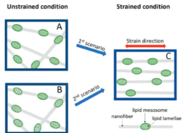
direction. The latter is resolved in the 2D pattern of 110% strain, shown by ellipsoids inFigure 6D, and confirms partial alignment of nanofibers along the stretching direction.24,75−77 The appearance of the diffraction peak from the lipid lamellar phase in the vertical direction is a very promising observation. We note that the lipid particles were initially mixed with the polymer in solution and hence randomly oriented before electrospinning and fiber formation. A plausible model with two possible scenarios could explain the preferred orientation of lipid lamellae in hybrid membranes under strain as shown in
Figure 7. First, the lamellae from the lipid (Lc phase) align
along thefiber axis, while the drag forces are imposed during electrospinning. Under this assumption, the lipid lamellae have already been aligned within an individual encapsulating nanofiber (Figure 7A). Nevertheless, they show a random orientation (an isotropic diffraction peak in the SAXS profile) because the nanofibers are randomly aligned prior to stretching. Upon uniaxial stretching, the nanofibers get aligned, and as a consequence, the lipid lamellae take a preferred orientation, schematically presented inFigure 7C, resulting in two diffraction arcs in the vertical direction of the SAXS profile. In the second scenario, the lipid lamellae are randomly aligned within their encapsulating nanofibers (Figure 7B). Applying uniaxial strains not only leads to the alignment of nanofibers but also induces an internal structure modification, i.e., the alignment of lipid lamellae with respect to the main axis of encapsulating nanofibers (Figure 7C). Verifying either of the above scenarios requires further investigations, e.g., the structural variation in an in situ electrospinning process. Regardless of what the mechanism of orientation is, the
evolution of nanoscale anisotropy by simply stretching membranes is an outstanding feature in our design and can offer new functional features, i.e., responsive release at varying strain conditions.
■
CONCLUSIONSThe lipid self-assemblies from lyotropic liquid crystalline particles (cubosomes) have been processed by electrospinning to produce bioinspired nanofiber membranes with internal hierarchy.
SAXS studies revealed that the Im3̅m structural symmetry of monoolein-based cubosomes was preserved after mixing with PEO in solution, while a few percent expansion in the lattice parameter was identified. After the fiber formation process by electrospinning, reorganization of the internal phase in lipid particles, from cubosomes of Im3̅m to mesosomes of crystalline lamellar phase (Lc), was observed. This transition was
explained as a change in the interfacial curvature of lipid bilayers due to the low water content within the fiber; possessing a lipid’s critical packing parameter of unity at Lc.
The combination of SEM, CLSM, TEM, and X-ray CT techniques confirmed the embedding of lipid mesosomes within thefibers. Mesosomes also imposed a welding behavior at the nanofiber junctions and increased porosity in the hybrid membranes if compared to the pure PEO membrane.
By in situ humidity-SAXS experiments, the retrieved Im3̅m cubic phase was demonstrated by water intake into thefibers. This phase reorganization occurred after a transient fluid lamellar phase (Lα) observation, confirming a responsive
behavior in the designed hybrid membranes. Moreover, the strain−SAXS experiments showed that not only the fibers aligned in the microscale under external stretching force but also an anisotropic feature was developed in the nanoscale within those fibers by the alignment of lipid lamellar phases. This is an outstanding feature in the evolution of nanoscale anisotropy which offers new possibilities for mediating the functional properties of electrospun fibers, such as the controlled release rate by the external strain or the interactions with biointerfaces for directional growth of cells.
Advanced nanofiber configurations such as core−shell and multicomponent nanofibers may also be prepared through coaxial electrospinning, and use of mesosomes with various internal morphologies such as hexosomes would be of future interest. The interactions with biology in correlations with the internal structure and anisotropy are yet to be understood to apply this class of new materials to tackle current challenges in biomedicine, tissue engineering, and health care domains.
■
ASSOCIATED CONTENT*
sı Supporting InformationThe Supporting Information is available free of charge at
https://pubs.acs.org/doi/10.1021/acs.langmuir.0c01487. Details of calculation of the lattice parameter in Im3̅m cubic phase, SEM images for pure PEO nanofibers at different concentrations and the nanofibers size distribution, solution viscosity of PEO/lipid mixtures at different ratios, size distribution of pure PEO and PEO/lipid nanofibers, FTIR spectrum of pure PEO and PEO/lipid nanofiber membranes, schematic illustration of an in situ humidity-SAXS setup for time-resolved experiment (PDF)
Figure 7. Possible scenarios explaining how the lipid lamellae in a PEO/lipid hybrid membrane can take a preferred orientation with an external mechanical strain. (A) Schematic presentation of lipid lamellae aligned with respect to their encapsulating nanofiber. (B) Random alignment of lipid lamellae within the nanofibers. (C) Lipid lamellae and nanofibers alignment in the membranes under external mechanical strain, as concluded from 2D-SAXS patterns.
■
AUTHOR INFORMATIONCorresponding Author
Amin Sadeghpour− Center for X-Ray Analytics and Laboratory for Biomimetic Membranes and Textiles, Empa, Swiss Federal Laboratories for Materials Science and Technology, St. Gallen CH-9014, Switzerland; orcid.org/ 0000-0002-0475-7858; Email:[email protected]
Authors
Nguyen D. Tien− Center for X-Ray Analytics and Laboratory for Biomimetic Membranes and Textiles, Empa, Swiss Federal Laboratories for Materials Science and Technology, St. Gallen CH-9014, Switzerland
Anjani K. Maurya− Center for X-Ray Analytics and Laboratory for Biomimetic Membranes and Textiles, Empa, Swiss Federal Laboratories for Materials Science and Technology, St. Gallen CH-9014, Switzerland; Cellular and Biomedical Sciences, Faculty of Medicine, University of Bern, Bern CH-3012, Switzerland; orcid.org/0000-0002-9134-6693
Giuseppino Fortunato− Laboratory for Biomimetic
Membranes and Textiles, Empa, Swiss Federal Laboratories for Materials Science and Technology, St. Gallen CH-9014, Switzerland; orcid.org/0000-0002-3889-7816
Markus Rottmar− Laboratory for Biointerfaces, Empa, Swiss Federal Laboratories for Materials Science and Technology, St. Gallen CH-9014, Switzerland; orcid.org/0000-0001-7636-428X
Robert Zboray− Center for X-Ray Analytics, Empa, Swiss Federal Laboratories for Materials Science and Technology, St. Gallen CH-9014, Switzerland
Rolf Erni− Electron Microscopy Center, Empa, Swiss Federal Laboratories for Materials Science and Technology, Dübendorf CH-8600, Switzerland; orcid.org/0000-0003-2391-5943
Alex Dommann− Center for X-Ray Analytics, Empa, Swiss Federal Laboratories for Materials Science and Technology, St. Gallen CH-9014, Switzerland; Cellular and Biomedical Sciences, Faculty of Medicine, University of Bern, Bern CH-3012, Switzerland
René M. Rossi − Laboratory for Biomimetic Membranes and Textiles, Empa, Swiss Federal Laboratories for Materials Science and Technology, St. Gallen CH-9014, Switzerland
Antonia Neels− Center for X-Ray Analytics, Empa, Swiss Federal Laboratories for Materials Science and Technology, St. Gallen CH-9014, Switzerland; Department of Chemistry, University of Fribourg, Fribourg 79085, Switzerland;
orcid.org/0000-0001-5752-2852
Complete contact information is available at:
https://pubs.acs.org/10.1021/acs.langmuir.0c01487
Notes
The authors declare no competingfinancial interest.
Data availability. The data and metadata supporting all plots shown in this paper are available upon request from the corresponding author.
■
ACKNOWLEDGMENTSA.S. acknowledgesfinancial support by the Marie Skłodowska-Curie fellowship and EMPAPOSTDOCS-II program. The program was supported by the European Union’s Horizon 2020 research and innovation under grant agreement no. 754364.
■
REFERENCES(1) Greiner, A.; Wendorff, J. H. Electrospinning: A fascinating method for the preparation of ultrathin fibres. Angew. Chem., Int. Ed. 2007, 46 (30), 5670−5703.
(2) Bhardwaj, N.; Kundu, S. C. Electrospinning: A fascinating fiber fabrication technique. Biotechnol. Adv. 2010, 28 (3), 325−347.
(3) Xue, J.; Xie, J.; Liu, W.; Xia, Y. Electrospun Nanofibers: New Concepts, Materials, and Applications. Acc. Chem. Res. 2017, 50 (8), 1976−1987.
(4) Xue, J.; Wu, T.; Dai, Y.; Xia, Y. Electrospinning and Electrospun Nanofibers: Methods, Materials, and Applications. Chem. Rev. 2019, 119 (8), 5298−5415.
(5) Ding, J.; Zhang, J.; Li, J.; Li, D.; Xiao, C.; Xiao, H.; Yang, H.; Zhuang, X.; Chen, X. Electrospun polymer biomaterials. Prog. Polym. Sci. 2019, 90, 1−34.
(6) Sun, B.; Long, Y. Z.; Zhang, H. D.; Li, M. M.; Duvail, J. L.; Jiang, X. Y.; Yin, H. L. Advances in three-dimensional nanofibrous macrostructures via electrospinning. Prog. Polym. Sci. 2014, 39 (5), 862−890.
(7) Han, J.; Xiong, L.; Jiang, X.; Yuan, X.; Zhao, Y.; Yang, D. Bio-functional electrospun nanomaterials: From topology design to biological applications. Prog. Polym. Sci. 2019, 91, 1−28.
(8) Wen, P.; Wen, Y.; Zong, M.-H.; Linhardt, R. J.; Wu, H. Encapsulation of Bioactive Compound in Electrospun Fibers and Its Potential Application. J. Agric. Food Chem. 2017, 65 (42), 9161−9179. (9) Weishaupt, R.; Zünd, J. N.; Heuberger, L.; Zuber, F.; Faccio, G.; Robotti, F.; Ferrari, A.; Fortunato, G.; Ren, Q.; Maniura-Weber, K.; Guex, A. G. Antibacterial, Cytocompatible, Sustainably Sourced: Cellulose Membranes with Bifunctional Peptides for Advanced Wound Dressings. Adv. Healthcare Mater. 2020, 9 (7), 1901850.
(10) Koski, A.; Yim, K.; Shivkumar, S. Effect of molecular weight on fibrous PVA produced by electrospinning. Mater. Lett. 2004, 58 (3), 493−497.
(11) Frohbergh, M. E.; Katsman, A.; Botta, G. R.; Lazarovici, P.; Schauer, C. L.; Wegst, U. G. K.; Lelkes, P. I. Electrospun hydroxyapatite-containing chitosan nanofibers crosslinked with genipin for bone tissue engineering. Biomaterials 2012, 33 (36), 9167−9178.
(12) Nezarati, R. M.; Eifert, M. B.; Cosgriff-Hernandez, E. Effects of Humidity and Solution Viscosity on Electrospun Fiber Morphology. Tissue Eng., Part C 2013, 19 (10), 810−819.
(13) Keirouz, A.; Chung, M.; Kwon, J.; Fortunato, G.; Radacsi, N. 2D and 3D electrospinning technologies for the fabrication of nanofibrous scaffolds for skin tissue engineering: A review. Wiley Interdiscip. Rev.: Nanomed. Nanobiotechnol. 2020, 12 (4), e1626.
(14) Mendes, A. C.; Stephansen, K.; Chronakis, I. S. Electrospinning of food proteins and polysaccharides. Food Hydrocolloids 2017, 68, 53−68.
(15) Chen, H.; Elabd, Y. A. Polymerized ionic liquids: Solution properties and electrospinning. Macromolecules 2009, 42 (9), 3368− 3373.
(16) Pignatelli, C.; Perotto, G.; Nardini, M.; Cancedda, R.; Mastrogiacomo, M.; Athanassiou, A. Electrospun silk fibroin fibers for storage and controlled release of human platelet lysate. Acta Biomater. 2018, 73, 365−376.
(17) Liu, C.; Zhu, C.; Li, J.; Zhou, P.; Chen, M.; Yang, H.; Li, B. The effect of the fibre orientation of electrospun scaffolds on the matrix production of rabbit annulus fibrosus-derived stem cells. Bone Res. 2015, 3, 15012.
(18) Greiner, A. M.; Sales, A.; Chen, H.; Biela, S. A.; Kaufmann, D.; Kemkemer, R. Nano- and microstructured materials for in vitro studies of the physiology of vascular cells. Beilstein J. Nanotechnol. 2016, 7, 1620−1641.
(19) Wang, C.; Wang, J.; Zeng, L.; Qiao, Z.; Liu, X.; Liu, H.; Zhang, J.; Ding, J. Fabrication of Electrospun Polymer Nanofibers with Diverse Morphologies. Molecules 2019, 24 (5), 834.
(20) Chen, S.; John, J. V.; McCarthy, A.; Xie, J. New forms of electrospun nanofiber materials for biomedical applications. J. Mater. Chem. B 2020, 8 (17), 3733−3746.
(21) Gazzano, M.; Gualandi, C.; Zucchelli, A.; Sui, T.; Korsunsky, A. M.; Reinhard, C.; Focarete, M. L. Structure-morphology correlation in electrospun fibers of semicrystalline polymers by simultaneous synchrotron SAXS-WAXD. Polymer 2015, 63, 154−163.
(22) Kogikoski, S.; Liberato, M. S.; Factori, I. M.; da Silva, E. R.; Oliveira, C. L. P.; Ando, R. A.; Alves, W. A. Polycaprolactone-Polyaniline Blend: Effects of the Addition of Cysteine on the Structural and Molecular Properties. J. Phys. Chem. C 2017, 121 (1), 863−877.
(23) Morel, A.; Domaschke, S.; Urundolil Kumaran, V.; Alexeev, D.; Sadeghpour, A.; Ramakrishna, S. N.; Ferguson, S. J.; Rossi, R. M.; Mazza, E.; Ehret, A. E.; Fortunato, G. Correlating diameter, mechanical and structural properties of poly(l-lactide) fibres from needleless electrospinning. Acta Biomater. 2018, 81, 169−183.
(24) Maurya, A. K.; Weidenbacher, L.; Spano, F.; Fortunato, G.; Rossi, R. M.; Frenz, M.; Dommann, A.; Neels, A.; Sadeghpour, A. Structural insights into semicrystalline states of electrospun nano-fibers: a multiscale analytical approach. Nanoscale 2019, 11 (15), 7176−7187.
(25) Lee, S. J.; Heo, D. N.; Moon, J.-H.; Ko, W.-K.; Lee, J. B.; Bae, M. S.; Park, S. W.; Kim, J. E.; Lee, D. H.; Kim, E.-C.; Lee, C. H.; Kwon, I. K. Electrospun chitosan nanofibers with controlled levels of silver nanoparticles. Preparation, characterization and antibacterial activity. Carbohydr. Polym. 2014, 111, 530−537.
(26) Zhang, S. K.; He, G. H.; Gong, X.; Zhu, X. P.; Wu, X. M.; Sun, X. Y.; Zhao, X. Y.; Li, H. Electrospun nanofiber enhanced sulfonated poly (phthalazinone ether sulfone ketone) composite proton exchange membranes. J. Membr. Sci. 2015, 493, 58−65.
(27) Zahmatkesh, S.; Zebarjad, S. M.; Bahrololoom, M. E.; Dabiri, E.; Arab, S. M. Synthesis of ZnO/In2O3 composite nanofibers by co-electrospinning: A comprehensive parametric investigating the process. Ceram. Int. 2019, 45, 2530−2541.
(28) Krishnamurthy, S.; Vaiyapuri, R.; Zhang, L.; Chan, J. M. Lipid-coated polymeric nanoparticles for cancer drug delivery. Biomater. Sci. 2015, 3 (7), 923−36.
(29) Hallan, S. S.; Kaur, P.; Kaur, V.; Mishra, N.; Vaidya, B. Lipid polymer hybrid as emerging tool in nanocarriers for oral drug delivery. Artif. Cells, Nanomed., Biotechnol. 2016, 44 (1), 334−349.
(30) Mezzenga, R.; Seddon, J. M.; Drummond, C. J.; Boyd, B. J.; Schröder-Turk, G. E.; Sagalowicz, L. Nature-Inspired Design and Application of Lipidic Lyotropic Liquid Crystals. Adv. Mater. 2019, 31 (35), 1900818.
(31) Rappolt, M.; Di Gregorio, G. M.; Almgren, M.; Amenitsch, H.; Pabst, G.; Laggner, P.; Mariani, P. Non-equilibrium formation of the cubic Pn3m phase in a monoolein/water system. Europhys. Lett. 2006, 75, 267−273.
(32) Sadeghpour, A.; Pirolt, F.; Glatter, O. Submicrometer-Sized Pickering Emulsions Stabilized by Silica Nanoparticles with Adsorbed Oleic Acid. Langmuir 2013, 29 (20), 6004−6012.
(33) Chong, J. Y. T.; Mulet, X.; Keddie, D. J.; Waddington, L.; Mudie, S. T.; Boyd, B. J.; Drummond, C. J. Novel Steric Stabilizers for Lyotropic Liquid Crystalline Nanoparticles: PEGylated-Phytanyl Copolymers. Langmuir 2015, 31 (9), 2615−2629.
(34) Murgia, S.; Falchi, A. M.; Meli, V.; Schillén, K.; Lippolis, V.; Monduzzi, M.; Rosa, A.; Schmidt, J.; Talmon, Y.; Bizzarri, R.; Caltagirone, C. Cubosome formulations stabilized by a dansyl-conjugated block copolymer for possible nanomedicine applications. Colloids Surf., B 2015, 129, 87−94.
(35) Bhatt, A.; Barnes, T.; Prestidge, C. Silica Nanoparticle Stabilization of Liquid Crystalline Lipid Dispersions: Impact on Enzymatic Digestion and Drug Solubilization. Curr. Drug Delivery 2015, 12 (1), 47−55.
(36) Barriga, H. M. G.; Holme, M. N.; Stevens, M. M. Cubosomes: The Next Generation of Smart Lipid Nanoparticles? Angew. Chem., Int. Ed. 2019, 58 (10), 2958−2978.
(37) Karami, Z.; Hamidi, M. Cubosomes: remarkable drug delivery potential. Drug Discovery Today 2016, 21 (5), 789−801.
(38) Spicer, P. T. Progress in liquid crystalline dispersions: Cubosomes. Curr. Opin. Colloid Interface Sci. 2005, 10 (5), 274−279.
(39) Mulet, X.; Boyd, B. J.; Drummond, C. J. Advances in drug delivery and medical imaging using colloidal lyotropic liquid crystalline dispersions. J. Colloid Interface Sci. 2013, 393, 1−20.
(40) Salentinig, S.; Zabara, M.; Parisse, P.; Amenitsch, H. Formation of highly ordered liquid crystalline coatings − an in situ GISAXS study. Phys. Chem. Chem. Phys. 2018, 20 (34), 21903−21909.
(41) Squires, A. M.; Templer, R. H.; Seddon, J. M.; Woenckhaus, J.; Winter, R.; Finet, S.; Theyencheri, N. Kinetics and Mechanism of the Lamellar to Gyroid Inverse Bicontinuous Cubic Phase Transition. Langmuir 2002, 18 (20), 7384−7392.
(42) Conn, C. E.; Ces, O.; Squires, A. M.; Mulet, X.; Winter, R.; Finet, S. M.; Templer, R. H.; Seddon, J. M. A Pressure-Jump Time-Resolved X-ray Diffraction Study of Cubic−Cubic Transition Kinetics in Monoolein. Langmuir 2008, 24 (6), 2331−2340.
(43) Squires, A. M.; Templer, R. H.; Seddon, J. M.; Woenkhaus, J.; Winter, R.; Narayanan, T.; Finet, S. Kinetics and mechanism of the interconversion of inverse bicontinuous cubic mesophases. Phys. Rev. E 2005, 72 (1), 011502.
(44) Moitzi, C.; Guillot, S.; Fritz, G.; Salentinig, S.; Glatter, O. Phase Reorganization in Self-Assembled Systems Through Interparticle Material Transfer. Adv. Mater. 2007, 19 (10), 1352−1358.
(45) Sadeghpour, A.; Pirolt, F.; Iglesias, G. R.; Glatter, O. Lipid Transfer between Submicrometer Sized Pickering ISAsome Emulsions and the Influence of Added Hydrogel. Langmuir 2014, 30 (10), 2639−2647.
(46) Iglesias, G. R.; Pirolt, F.; Sadeghpour, A.; Tomšič, M.; Glatter, O. Lipid Transfer in Oil-in-Water Isasome Emulsions: Influence of Arrested Dynamics of the Emulsion Droplets Entrapped in a Hydrogel. Langmuir 2013, 29 (50), 15496−15502.
(47) Hai, T.; Wan, X.; Yu, D.-G.; Wang, K.; Yang, Y.; Liu, Z.-P. Electrospun lipid-coated medicated nanocomposites for an improved drug sustained-release profile. Mater. Des. 2019, 162, 70−79.
(48) Huang, T. C.; Toraya, H.; Blanton, T. N.; Wu, Y. X-ray powder diffraction analysis of silver behenate, a possible low-angle diffraction standard. J. Appl. Crystallogr. 1993, 26 (2), 180−184.
(49) GmbH, B. A. Nanography-Two Dimensional Scanning SAXS with the NANOSTAR-Lab Report; https://my.bruker.com/acton/ attachment/2655/f-0e3b/1/-/-/-/-/.
(50) Kim, H.; Leal, C. Cuboplexes: Topologically Active siRNA Delivery. ACS Nano 2015, 9 (10), 10214−10226.
(51) Sadeghpour, A.; Sanver, D.; Rappolt, M., Chapter Four -Interactions of Flavonoids With Lipidic Mesophases. In Advances in Biomembranes and Lipid Self-Assembly, Iglič, A., Garcia-Sáez, A., Rappolt, M., Eds.; Academic Press: 2017; Vol. 25, pp 95−123.
(52) Chong, J. Y. T.; Mulet, X.; Waddington, L. J.; Boyd, B. J.; Drummond, C. J. Steric stabilisation of self-assembled cubic lyotropic liquid crystalline nanoparticles: high throughput evaluation of triblock polyethylene oxide-polypropylene oxide-polyethylene oxide copoly-mers. Soft Matter 2011, 7 (10), 4768−4777.
(53) Huang, Y.; Gui, S. Factors affecting the structure of lyotropic liquid crystals and the correlation between structure and drug diffusion. RSC Adv. 2018, 8 (13), 6978−6987.
(54) Engblom, J.; Miezis, Y.; Nylander, T.; Razumas, V.; Larsson, K. On the swelling of monoolein liquid-crystalline aqueous phases in the presence of distearoylphosphatidylglycerol; Springer Berlin Heidelberg: Berlin, Heidelberg, 2001; pp 9−15.
(55) Tyler, A. I. I.; Barriga, H. M. G.; Parsons, E. S.; McCarthy, N. L. C.; Ces, O.; Law, R. V.; Seddon, J. M.; Brooks, N. J. Electrostatic swelling of bicontinuous cubic lipid phases. Soft Matter 2015, 11 (16), 3279−3286.
(56) Kim, H.; Song, Z.; Leal, C. Super-swelled lyotropic single crystals. Proc. Natl. Acad. Sci. U. S. A. 2017, 114 (41), 10834.
(57) Cherezov, V.; Clogston, J.; Misquitta, Y.; Abdel-Gawad, W.; Caffrey, M. Membrane protein crystallization in meso: lipid type-tailoring of the cubic phase. Biophys. J. 2002, 83 (6), 3393−407.
(58) Israelachvili, J. N. Soft and Biological Structures. In Intermolecular and Surface Forces, 3rd ed.; Israelachvili, J. N., Ed.; Academic Press: San Diego, CA, 2011; pp 535−576.
(59) Kluzek, M.; Tyler, A. I. I.; Wang, S.; Chen, R.; Marques, C. M.; Thalmann, F.; Seddon, J. M.; Schmutz, M. Influence of a pH-sensitive polymer on the structure of monoolein cubosomes. Soft Matter 2017, 13 (41), 7571−7577.
(60) Fong, H.; Chun, I.; Reneker, D. H. Beaded nanofibers formed during electrospinning. Polymer 1999, 40 (16), 4585−4592.
(61) Deitzel, J. M.; Kleinmeyer, J.; Harris, D.; Beck Tan, N. C. The effect of processing variables on the morphology of electrospun nanofibers and textiles. Polymer 2001, 42 (1), 261−272.
(62) Tripatanasuwan, S.; Zhong, Z.; Reneker, D. H. Effect of evaporation and solidification of the charged jet in electrospinning of poly(ethylene oxide) aqueous solution. Polymer 2007, 48 (19), 5742− 5746.
(63) Pelipenko, J.; Kristl, J.; Janković, B.; Baumgartner, S.; Kocbek, P. The impact of relative humidity during electrospinning on the morphology and mechanical properties of nanofibers. Int. J. Pharm. 2013, 456 (1), 125−134.
(64) Mezzenga, R.; Meyer, C.; Servais, C.; Romoscanu, A. I.; Sagalowicz, L.; Hayward, R. C. Shear Rheology of Lyotropic Liquid Crystals: A Case Study. Langmuir 2005, 21 (8), 3322−3333.
(65) Qiu, H.; Caffrey, M. Lyotropic and Thermotropic Phase Behavior of Hydrated Monoacylglycerols: Structure Characterization of Monovaccenin. J. Phys. Chem. B 1998, 102 (24), 4819−4829.
(66) Kulkarni, C. V.; Tang, T.-Y.; Seddon, A. M.; Seddon, J. M.; Ces, O.; Templer, R. H. Engineering bicontinuous cubic structures at the nanoscalethe role of chain splay. Soft Matter 2010, 6 (14), 3191− 3194.
(67) Conn, C. E.; Ces, O.; Mulet, X.; Finet, S.; Winter, R.; Seddon, J. M.; Templer, R. H. Dynamics of Structural Transformations between Lamellar and Inverse Bicontinuous Cubic Lyotropic Phases. Phys. Rev. Lett. 2006, 96 (10), 108102.
(68) Angelov, B.; Angelova, A.; Mutafchieva, R.; Lesieur, S.; Vainio, U.; Garamus, V. M.; Jensen, G. V.; Pedersen, J. S. SAXS investigation of a cubic to a sponge (L3) phase transition in self-assembled lipid nanocarriers. Phys. Chem. Chem. Phys. 2011, 13 (8), 3073−3081.
(69) Kołbuk, D.; Sajkiewicz, P.; Maniura-Weber, K.; Fortunato, G. Structure and morphology of electrospun polycaprolactone/gelatine nanofibres. Eur. Polym. J. 2013, 49 (8), 2052−2061.
(70) Schneider, C. A.; Rasband, W. S.; Eliceiri, K. W. NIH Image to ImageJ: 25 years of image analysis. Nat. Methods 2012, 9 (7), 671− 675.
(71) Zillohu, U. A.; Alissawi, N.; Abdelaziz, R.; Elbahri, M. Thermo-Plasmonics for Localized Graphitization and Welding of Polymeric Nanofibers. Materials 2014, 7 (1), 323.
(72) Shi, Z.; Jin, G.; Wang, J.; Zhang, J. Free-standing, welded mesoporous carbon nanofibers as anode for high-rate performance Li-ion batteries. J. Electroanal. Chem. 2017, 795, 26−31.
(73) Czeslik, C.; Winter, R.; Rapp, G.; Bartels, K. Temperature- and pressure-dependent phase behavior of monoacylglycerides monoolein and monoelaidin. Biophys. J. 1995, 68 (4), 1423−1429.
(74) Tran, N.; Zhai, J.; Conn, C. E.; Mulet, X.; Waddington, L. J.; Drummond, C. J. Direct Visualization of the Structural Trans-formation between the Lyotropic Liquid Crystalline Lamellar and Bicontinuous Cubic Mesophase. J. Phys. Chem. Lett. 2018, 9 (12), 3397−3402.
(75) Richard-Lacroix, M.; Pellerin, C. Molecular Orientation in Electrospun Fibers: From Mats to Single Fibers. Macromolecules 2013, 46 (24), 9473−9493.
(76) Miyazaki, T.; Hoshiko, A.; Akasaka, M.; Sakai, M.; Takeda, Y.; Sakurai, S. Structure Model of a Poly(vinyl alcohol) Film Uniaxially Stretched in Water and the Role of Crystallites on the Stress−Strain Relationship. Macromolecules 2007, 40 (23), 8277−8284.
(77) Papkov, D.; Delpouve, N.; Delbreilh, L.; Araujo, S.; Stockdale, T.; Mamedov, S.; Maleckis, K.; Zou, Y.; Andalib, M. N.; Dargent, E.; Dravid, V. P.; Holt, M. V.; Pellerin, C.; Dzenis, Y. A. Quantifying Polymer Chain Orientation in Strong and Tough Nanofibers with Low Crystallinity: Toward Next Generation Nanostructured Super-fibers. ACS Nano 2019, 13 (5), 4893−4927.