HAL Id: hal-00801727
https://hal.archives-ouvertes.fr/hal-00801727
Submitted on 18 Mar 2013
HAL is a multi-disciplinary open access
archive for the deposit and dissemination of
sci-entific research documents, whether they are
pub-lished or not. The documents may come from
teaching and research institutions in France or
abroad, or from public or private research centers.
L’archive ouverte pluridisciplinaire HAL, est
destinée au dépôt et à la diffusion de documents
scientifiques de niveau recherche, publiés ou non,
émanant des établissements d’enseignement et de
recherche français ou étrangers, des laboratoires
publics ou privés.
LES evaluation of the effects of equivalence ratio
fluctuations on the dynamic flame response in a real gas
turbine combustion chamber
Sebastian Hermeth, Gabriel Staffelbach, Laurent Gicquel, Thierry Poinsot
To cite this version:
Sebastian Hermeth, Gabriel Staffelbach, Laurent Gicquel, Thierry Poinsot. LES evaluation of the
effects of equivalence ratio fluctuations on the dynamic flame response in a real gas turbine
com-bustion chamber. Proceedings of the Comcom-bustion Institute, Elsevier, 2013, vol. 34, pp.3165-3173.
�10.1016/j.proci.2012.07.013�. �hal-00801727�
This is an author-deposited version published in :
http://oatao.univ-toulouse.fr/
Eprints ID : 8580
To link to this article : DOI:10.1016/j.proci.2012.07.013
URL :
http://dx.doi.org/10.1016/j.proci.2012.07.013
O
pen
A
rchive
T
OULOUSE
A
rchive
O
uverte (
OATAO
)
OATAO is an open access repository that collects the work of Toulouse researchers and
makes it freely available over the web where possible.
To cite this version :
Hermeth, Sebastian and Staffelbach, Gabriel and Gicquel, Laurant
and Poinsot, Thierry
LES evaluation of the effects of equivalence
ratio fluctuations on the dynamic flame response in a real gas
turbine combustion chamber.
(2013) Proceedings of the
Combustion Institute, vol. 34 (n° 2). pp. 3165-3173. ISSN
1540-7489
Any correspondence concerning this service should be sent to the repository
administrator:
staff-oatao@listes.diff.inp-toulouse.fr
LES evaluation of the effects of equivalence ratio fluctuations on the dynamic
flame response in a real Gas Turbine Combustion Chamber
Hermeth S.⋆, Staffelbach G.⋆, Gicquel L. Y. M.⋆, Poinsot T.⋆,†
⋆CERFACS, 42 Avenue G. Coriolis, 31057 Toulouse cedex, France †
Institut de M´ecanique des Fluides de Toulouse, Avenue C. Soula, 31400 Toulouse, France
Corresponding author: Sebastian Hermeth
Address: CERFACS, CFD Team, 42 Avenue G. Coriolis, 31057 Toulouse Cedex 01, France. Tel: +33 (0)5 61 19 30 22; fax: +33 (0)5 61 19 30 00.
Email: hermeth@cerfacs.fr
Colloquium topic: IC engine and gas turbine combustion.
Total length of paper (method 1): 6132 - Abstract: 197 - Main text: 3084 - Equations: 46 - Eq. 1: 23 ((1+2) x 7.6 x 1) - Eq. 2: 23 ((1+2) x 7.6 x 1) - References: 630 ((34+2) x 2.3 x 7.6) - Tables: 160 - Tab. 1: 107 ((5+2) x 7.6 x 2) - Tab. 2: 53 ((5+2)) x 7.6 x 1) - Figures: 2212
- Fig. 1: 218 ((34+10) x 2.2 x 2 + 24) - Fig. 2: 107 ((30+10) x 2.2 x 1 + 19) - Fig. 3: 253 ((43+10) x 2.2 x 2 + 19) - Fig. 4: 348 ((62+10) x 2.2 x 2 + 31) - Fig. 5: 348 ((62+10) x 2.2 x 2 + 31) - Fig. 6: 141 ((45+10) x 2.2 x 1 + 20) - Fig. 7: 103 ((30+10) x 2.2 x 1 + 15) - Fig. 8: 109 ((30+10) x 2.2 x 1 + 15) - Fig. 9: 117 ((39+10) x 2.2 x 1 + 9) - Fig. 10: 128 ((39+10) x 2.2 x 1 + 20) - Fig. 11: 118 ((40+10) x 2.2 x 1 + 8) - Fig. 12: 110 ((38+10) x 2.2 x 1 + 4) - Fig. 13: 118 ((37+10) x 2.2 x 1 + 14)
Abstract
Large Eddy Simulations (LES) of a lean swirl-stabilized gas turbine burner are used to analyze mechanisms triggering combustion instabilities. To separately study the effect of velocity and equivalence ratio fluctu-ations, two LES of the same geometry are performed: one where the burner operates in a ”technically” premixed mode (methane is injected by holes in the vanes located in the diagonal passage upstream of the chamber) and the second one where the flow is fully premixed in the diagonal passage. The inlet is acousti-cally modulated and the mechanisms affecting the dynamic flame response are identified. LES reveals that both cases provide similar averaged (non-)pulsated flame shapes. However, even though the mean flames are only slightly modified, the delays change when mixing is not perfect. LES fields and a simple model for the methane jets trajectories show that mixing in the diagonal passage is not sufficient to damp heterogeneities induced by unsteady fuel flow rate and varying fuel jet trajectories. These mixing fluctuations are phased with velocity oscillations and modify the flame response to forcing. Local fields of delays and interaction indices are obtained, showing that the flame is not compact and is affected by fluctuations of mixing.
Keywords:
1. Introduction
Modern regulation policies on pollutant emissions lead to lean (technically) premixed combustion sys-tems [1]. These low-emission gas turbines are known to be particularly susceptible to thermo-acoustic instabilities [2] and their prediction has become an important task today to prevent the appearance of acoustically coupled instabilities at an early design stage [3, 4, 5]. For acoustically compact flames, a com-mon approach can be found in the literature and was first introduced by Crocco [6, 7]. In this approach, the Flame Transfer Function (FTF) is the key parameter and is defined as the ratio of the relative heat release fluctuation (ˆq/¯q) to the relative inlet velocity perturbation (ˆu/¯u) issued by the acoustic field. In the frequency domain it writes F (ω) = (ˆq/¯q)/(ˆu/¯u), with ω being the angular frequency. The FTF is affected by different mechanisms acting simultaneously on the heat release rate fluctuation and therefore difficult to separate [8] or evaluate accurately. Among the recent contributions towards the understanding of the mech-anisms at play for swirled flames, the importance of swirl number fluctuations has been clearly identified. Straub and Richards [9] first noticed a strong impact of the swirler position on the combustion oscillations. Hirsch et al. [10] hence investigated the effect of swirler designs and found that an additional time lag is responsible for changes in the FTF. Komarek et al. [11] investigated the influence of several swirler positions on the FTF and concluded that disturbances propagate at a convective and an acoustic speed downstream the swirler position. Finally, Palies et al. [12, 13] have shown that the acoustic perturbations reaching the swirler generate transverse velocity fluctuations which are convected by the flow. Swirl is not the only phenomenon affecting the FTF in real gas turbines: since most of them are partially premixed, fluctuations of equivalence ratio may also modify the flame response [14]. Schuermans et al. [15] compared the measured transfer matrix of a turbulent flame for a technically premixed and a fully premixed system and found the maximal value in amplitude to increase when equivalence ratio perturbations are present. Kim et al. [16] found a phase difference between equivalence ratio and velocity at the combustor inlet suggesting that this phase determines if both effects cancel out or amplify the dynamic flame response. Furthermore, they showed that this phase difference is a function of frequency, fuel injection location, fuel injector impedance and the mean velocity in the nozzle.
These mechanisms have been studied for simple laboratory premixed flames but much less information is available for real gas turbines. This point is investigated here using LES of a real burner. Thanks to this fully unsteady numerical approach, effects of mass flow rate perturbation and mixture fluctuation can be studied. To study the effect of mixing, two LES of the same geometry are performed. For the first one, the burner operates in technically premixed mode where fuel is injected through small holes in the vanes of the diagonal swirler and mixes downstream with air prior to combustion. A second simulation is performed with a fully premixed flow passing through the diagonal swirler thereby cancelling any potential effect on the FTF due to modulated mixing.
In the following, the modeling used for LES will be first described followed by a description of the target configuration, the mesh and boundary conditions retained for the computation. Averaged reactive flow fields for both configurations are then discussed and the mechanisms affecting the dynamic flame response are analyzed based on the forced reacting flow fields obtained by LES.
2. Large Eddy Simulation
LES is well suited to unsteady combustion and is a useful tool to predict thermoacoustics and FTFs [2, 11, 5]. The code used here is a fully compressible explicit code which solves the reactive multi-species Navier-Stokes equations on unstructured grids using a cell-vertex approximation [17]. A second-order finite element scheme is used for both time and space advancement [18, 19]. The Sub-grid stress tensor is modeled by a classical Smagorinsky approach [20]. Chemistry is computed using a two-step mechanism for methane/air flames [21, 22] where chemistry is modeled using two reactions and six species (CH4, O2, CO2, CO, H2O
and N2). The first reaction is irreversible and controls the oxydation of CH4 while the second reaction is
reversible leading to an equilibrium between CO and CO2 [23]. To capture flame/turbulence interactions,
the dynamic thickened flame model is used [24, 25, 26]. Sub-gridscale wrinkling and interactions are modeled using an efficiency function [24, 25, 26] which is well suited for all flames studied here which all correspond to the premixed or partially premixed regime.
3. Target configuration
The burner considered here is a hybrid burner operated at high pressure possessing multiple air and fuel inlets (Fig. 1). Air is injected through two coaxial swirlers (diagonal and axial) with the main air mass flow rate passing through the diagonal passage. The diagonal and axial swirler contain 24 and 8 vanes respectively. Methane is injected through small holes in the vanes of the diagonal passage and mixes with air before reaching the combustion chamber where the flame stabilizes due to vortex breakdown [27, 28]. To help flame stabilization a pilot methane injection is added in the axial part. Cooling air inlets are also present to shield the Cylindrical Burner Outlet (CBO) and the lance seen on Fig. 1. Finally, the burner is mounted on a 15 degree section of an annular combustion chamber constituting the computational domain retained for our computations (Fig. 1).
3.1. Mesh And Boundary Conditions
LES are performed on a fully unstructured mesh of 1.921.370 nodes and 10.472.070 tetrahedral elements. The time step is 9 · 10−8
s with the acoustic CFL number being 0.7 [29]. The mesh is refined in the flame region and in the vicinity of the fuel injection, Fig. 1. Inlet and outlet boundary conditions are imposed through the non-reflecting Navier-Stokes Characteristic Boundary Condition (NSCBC) formulation [30] to
control acoustic reflection. All walls are modeled using a logarithmic wall-law condition and side boundaries of the combustion chamber are considered axi-periodic.
To study the effects of local variations of mixing on the flame response, two different simulations are per-formed on the same geometry. In the first one, the burner is operating in ”technically” premixed mode, called TECH (table 1), where pure air enters the diagonal passage and pure fuel is injected through nine small holes in the vanes of the diagonal swirler. In the second simulation, referred to as FULL, a fully pre-mixed flow enters the diagonal passage so that the global equivalence ratio is kept constant in the diagonal part (table 1). Note that in both TECH and FULL cases, the fuel injected in the axial swirler remains pure, so that mixing heterogeneities are expected in both simulations.
Forcing is introduced by generating a harmonic acoustic perturbation at the diagonal inlet using the inlet wave modulation method [31]. The response of the flame is quantified by measuring the perturbation of the heat release rate. An amplitude of 6 percent of the mean inlet velocity is chosen, to be in the linear regime. The forcing frequency is 250 Hz. Tests have been performed to investigate the effect of pulsating the diagonal or axial passages separately. Pulsating only the diagonal swirler results in the same flame response as pulsating both axial and diagonal passages, so only the latter is discussed here.
4. Results and discussions
This section compares the two simulations TECH and FULL in terms of mean flow fields, flow field dynamics and FTFs.
4.1. Mean reacting flow fields 4.1.1. Mean non-pulsated flow fields
The normalized equivalence ratio ¯φ and an iso-line of temperature are shown in Fig. 2 for the mean results of both cases. The equivalence ratio is normalized by its value at the inlet of the diagonal swirler for the FULL case. In the TECH case the non-uniformity of mixture in the diagonal swirler is clearly visible. However, mixing takes place due to the rotational fluid motion and a quasi-uniform mixture reaches the flame front. Of course, for the FULL case, the mixture in the diagonal swirler has a constant equivalence ratio ( ¯φ = 1). Figure 2 shows that the two flames are very similar in terms of shapes but also of temperature and RMS temperature profiles (not shown here). Mixing can be analyzed by plotting the probability density functions (PDF) of normalized heat release versus local equivalence ratio ¯φ (Fig. 3). While the overall heat release is constant for both cases, a different combustion regime is found. The TECH flame produces slightly less heat release around ¯φ = 1 and more at ¯φ = 0.8 than the FULL case but differences between the two cases for the mean flow are limited. The next step consists of analyzing the influence of these different regimes on the forced flame.
4.1.2. Mean pulsated flow fields
The acoustic perturbation has a small impact on the combustion regime of both flames (Fig. 3). In both cases the pulsated flame produces less heat release at ¯φ = 1 and more around ¯φ = 0.8 than the non pulsated flame. This change in combustion regime has no impact on the position and shape of the flame. For both cases a very good agreement is found in terms of temperature and RMS temperature profiles between the pulsated and non pulsated flame (not shown here).
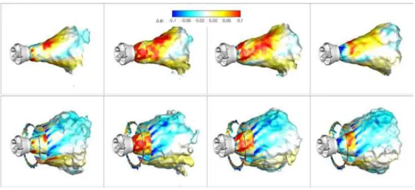
The differences in combustion regime between pulsated and non-pulsated flame can be analyzed by plotting iso-surfaces of temperature coloured by the difference of equivalence ratio between both flames defined as ∆φ = φ′
−φ with ˆˆ φ being the mean local equivalence ratio. The pulsated averaged flame is analyzed at different phase angles of the heat release oscillation cycle (Fig. 4 and Fig. 5). To isolate mixing effects in both passages, an ’inner’ flame region is defined as the part of the flame starting at the lance on the axial swirler and finishing at the flame tip. The TECH case shows a significantly richer mixture along the inner flame at the phase angle T /2. At 3T /2 the flame surface exhibits leaner mixture near the lance with lower positive equivalence ratio variation along the inner flame. The shape of the inner flame changes periodically opening and closing near the lance with the largest opening at T and the smallest at 2T . For all phase angles the outer flame region fed mainly by the diagonal passage shows a leaner mixture. Fluctuations in equivalence ratio for the FULL case are only due to the effect of the pilot flame. In this case the in-ner and outer flame region show globally much less mixture variation than in the TECH case. The richest mixture appears at the lance at 2T and a leaner mixture at T . The flame shape behaves as in the TECH case.
4.2. Dynamics of the reacting flow fields
The previous section has shown that both cases exhibit similar mean pulsated and non-pulsated flame shapes but show differences for the combustion regime. It is worth investigating how this affects the dynamics of the flame.
4.2.1. Dynamic flame response
The time variations of mean heat release rate and velocity fluctuation at the reference point A (Fig. 1) are given in Fig. 6. Time is normalized by the acoustic forcing period T . Since the reference velocity signal is identical for both simulations, only the reference signal for the TECH case is shown. A phase difference between the relative heat release signals is clearly visible and the amplitudes differ slightly. The global FTF is given in table 2 in terms of amplitude n and phase θ. Although the mean flame shape is not influenced by mixing heterogeneities, the dynamic response of the flame is changed especially in terms of time delay: the delay of the TECH case is 1.5 times the FULL case delay, showing that mixture fraction fluctuation in the diagonal swirler modifies the FTF.
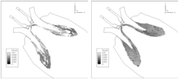
4.2.2. Local comparison of FTF
Figure 6 shows that the global response of the system is highly affected by mixing heterogeneities. It is therefore interesting to focus on the local response of the flame. Longitudinal cuts colored by the local amplitude and time delay are shown in Fig. 7 and Fig. 8 respectively. The amplitude response of the TECH case is intense near the lance and in the inner flame region. At the flame tip the amplitude varies strongly and is non-uniform. The FULL case shows less intense amplitude near the lance than the TECH case but behaves similarly in the inner flame region where a shear layer separates the flows of the axial and diagonal swirlers. Close to the flame tip and in the outer flame region, the amplitude is almost uniformly distributed but at slightly lower values than the TECH case. Although the global amplitude of both cases is similar, the local FTF fields reveal significant differences. The mixture fluctuations in the TECH case are phased with the velocity perturbations and propagate along the flame front affecting the local amplitude of the flame to higher and lower values whereas the FULL case shows a more uniformly distributed amplitude along the flame. A similar behaviour is observed for the time delay (Fig. 8). The FULL case has an almost uniformly distributed time delay for the whole flame region. The TECH case delay is distributed non uniformly in the reaction zone underlining the importance of mixture perturbation in such flames.
4.2.3. Mixture perturbation
Forcing causes not only an acoustic perturbation normal to the flame but also pressure fluctuations at the fuel injection holes. This results in two effects: 1) the injected fuel flow rate pulsates and 2) the trajectory of the fuel jet fluctuates. Figure 9 shows the fuel and air flow rate perturbation at the reference point B (Fig. 1). The air flow rate perturbation at this point is 12% of the mean axial component and the fuel flow rate fluctuation 5%. Note that the small fuel injection holes are fed by a plenum (Fig. 1) where the most important pressure drop occurs through the holes. This means that even when a non-reflecting boundary condition is imposed at the plenum, the impedance and therefore the fluctuations of fuel flow rate are captured realistically. The fuel velocity perturbation causes a variation of the fuel jet trajectory as well as a perturbation in mixture illustrated by two snapshots from LES in Fig.10 showing an iso-surface of methane mass fraction and the normalized equivalence ratio field. The oscillations of the fuel jet observed in the LES can be confirmed by literature data on jet in cross flows. Since fuel and air jets oscillate with different phases at the injection point, the resulting velocity ratio, which determines the trajectory of the jet and therefore the mixing, also oscillates. The corresponding momentum flux ratio J [32] is shown in Fig. 11 as a function of time and is defined as follows:
J = ρJ etU 2 J et ρ∞U 2 ∞ (1)
To describe the jet trajectory several analytical models can be found in the literature. Following Priere [33] the empirical relation given by Ivanov [34] reads:
x d = ! U∞ UJ et "2.6#y d $3 +y dcot(δ) (2)
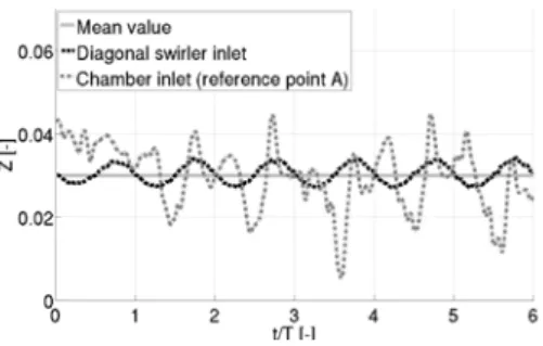
and allows to track the jet trajectory envelope resulting from an oscillating J. Figure 12 shows that J fluctuates from 120 to 240, leading to large trajectory fluctuations, as observed in the LES. Twenty diameters downstream of the vanes, Eq. 2 shows that the variations in J lead to lateral displacements of the jet of the order of ten diameters and obviously to fluctuations of local mixing. Both effects, the pulsating injected fuel flow rate and the fluctuating trajectory of the fuel jet have an impact on the mixing close to the injection (Fig.10). Generally, the diagonal swirler is designed to provide good mixing and to damp those effects. It is therefore interesting to investigate how mixing heterogeneities are transported between the vanes of the swirler and the chamber. Figure 13 shows that the global instantaneous inlet mixture fraction of the diagonal passage (defined as the ratio of the fuel flow rate to the total flow rate) oscillates at the forcing frequency between 0.025 and 0.035 which is about 10% of the mean value. At the inlet of the chamber (reference point A), after convection and mixing through the diagonal swirler, the local mixture fraction shows larger fluctuations than the global mixture fraction, demonstrating that the heterogeneities created at the chamber inlet are not only due to flow rate fluctuations but also to unsteady mixing in the swirler, induced by the unsteady movements of the methane jets.
5. Conclusions
Large-Eddy Simulations have been performed for a real gas turbine burner mounted on a 15 degree section of an annular combustion chamber. The effect of equivalence ratio perturbation has been studied separately by performing two LES of the same geometry: one with the burner operating in technically premixed (TECH) and the second with a fully premixed (FULL) flow passing through diagonal swirler. LES reveals that both cases exhibit similar mean pulsated and non-pulsated flame shapes but show differences for the combustion regime. Phase averaged solutions show that the technically premixed case is affected by mixture perturbation. This has an important effect on the global FTFs: the FTF delay for the TECH case is 1.5 times larger than for the FULL case and the interactive index slightly lower. Furthermore local FTF fields show that mixture heterogeneities propagating in the diagonal swirler lead to locally different responses over the flame region, whereas the FULL flame shows similar values of amplitude and time delay over the whole flame. LES and theory reveal that two mechanisms are responsible for the perturbation of mixture: 1) the pulsating injected fuel flow rate and 2) the fluctuating trajectory of the fuel jets. Even though mixing takes place in the diagonal swirler, mixture fluctuations are not damped at the combustion chamber inlet. They are phased with velocity fluctuations and combine with them to lead to different FTF results. This shows
that although fuel injection in this turbine was designed to produce good mixing, this is true only for steady flames. As soon as the flames are pulsated, LES reveals that the fuel injection system produces a response which is not the same as a fully premixed system.
Acknowledgements
The authors acknowledge the support of ANSALDO AEN and the funding by the EC in the Marie Curie ActionsNetworks for Initial Training program, under call FP7-PEOPLE-2007-1-1-ITN, Project LIMOUSINE with project number 214905 and CINES.
References
[1] A. H. Lefebvre, Gas Turbines Combustion, Taylor & Francis, 1999.
[2] T. Poinsot, D. Veynante, Theoretical and Numerical Combustion, R.T. Edwards, 2nd edition, 2005.
[3] W. Krebs, P. Flohr, B. Prade, S. Hoffmann, Thermoacoustic stability chart for high intense gas turbine combustion systems, 174 (2002) 99–128.
[4] R. Kaess, W. Polifke, T. Poinsot, N. Noiray, D. Durox, T. Schuller, S. Candel, Cfd-based mapping of the thermo-acoustic stability of a laminar premix burner, in: , Center for Turbulence Research, NASA AMES, Stanford University, USA, 2008, pp. 289–302.
[5] P. Wolf, G. Staffelbach, A. Roux, L. Gicquel, T. Poinsot, V. Moureau, Massively parallel les of azimuthal thermo-acoustic instabilities in annular gas turbines, M´ecanique 337 (6-7) (2009) 385–394.
[6] L. Crocco, Aspects of combustion instability in liquid propellant rocket motors. part i., 21 (1951) 163–178. [7] L. Crocco, Aspects of combustion instability in liquid propellant rocket motors. part ii., 22 (1952) 7–16.
[8] S. Thumuluru, H. Ma, T. Lieuwen, Measurements of the flame response to harmonic excitation in a swirl combustor, in: 45th AIAA Aerospace Sciences Meeting and Exhibit, AIAA Paper 2007-0845, Reno, USA, 2007.
[9] D. Straub, G. Richards, Effect of axial swirl vane location on effect of axial swirl vane location on effect of axial swirl vane location on combustion dynamics, in: ASME Paper 99-GT-109, 1999.
[10] C. Hirsch, D. Franca, P. Reddy, W. Polifke, T. Sattelmayer, Influence of the swirler design on the flame transfer function of premixed flames, ASME Paper GT2005-68195.
[11] T. Komarek, W. Polifke, Impact of swirl fluctuations on the flame response of a perfectly premixed swirl burner, Journal of Engineering for Gas Turbines and Power 132.
[12] P. Palies, D. Durox, T. Schuller, S. Candel, The combined dynamics of swirler and turbulent premixed swirling flames, 157 (2010) 1698–1717.
[13] P. Palies, T. Schuller, D. Durox, S. Candel, Modeling of premixed swirling flames transfer functions, in: Proceedings of the Combustion Institute, Vol. 33, 2011, pp. 2967–2974.
[14] T. Lieuwen, B. T. Zinn, The role of equivalence ratio oscillations in driving combustion instabilities in low nox gas turbines, 27 (1998) 1809–1816.
[15] B. Schuermans, V. Bellucci, F. Guethe, F. Meili, P. Flohr, C. Paschereit, A detailed analysis of thermoacoustic interaction mechanisms in a turbulent premixed flame, in: ASME Turbo Expo 2004-Power for Land Sea and Air, Vol. GT2004-53831, Vienna, Austria, 2004.
[16] K. Kim, J. Lee, B. Quay, D. Santavicca, Response of partially premixed flames to acoustic velocity and equivalence ratio perturbations, 157 (2010) 1731–1744.
[17] T. Schønfeld, M. Rudgyard, Steady and unsteady flows simulations using the hybrid flow solver avbp, 37 (11) (1999) 1378–1385.
[18] C. Hirsch, Numerical Computation of Internal and External Flows, Vol. 2, John Wiley & Sons, New York, 1990. [19] P. D. Lax, B. Wendroff, Systems of conservation laws, 13 (1960) 217–237.
[20] J. Smagorinsky, General circulation experiments with the primitive equations: 1. the basic experiment., 91 (1963) 99–164. [21] B. Franzelli, E. Riber, M. Sanjos´e, T. Poinsot, A two-step chemical scheme for large eddy simulation of kerosene-air flames,
Combustion and Flame 157 (7) (2010) 1364–1373.
[22] B. Franzelli, E. Riber, L. Gicquel, T. Poinsot, Large-eddy simulation of combustion instabilities in a lean partially premixed swirled flame, Combustion and Flame Submitted.
[23] L. Selle, G. Lartigue, T. Poinsot, R. Koch, K.-U. Schildmacher, W. Krebs, B. Prade, P. Kaufmann, D. Veynante, Com-pressible large-eddy simulation of turbulent combustion in complex geometry on unstructured meshes, 137 (4) (2004) 489–505.
[24] O. Colin, F. Ducros, D. Veynante, T. Poinsot, A thickened flame model for large eddy simulations of turbulent premixed combustion, 12 (7) (2000) 1843–1863.
[25] O. Colin, M. Rudgyard, Development of high-order taylor-galerkin schemes for unsteady calculations, 162 (2) (2000) 338–371.
[26] J.-P. L´egier, T. Poinsot, D. Veynante, Dynamically thickened flame LES model for premixed and non-premixed turbulent combustion, in: , Center for Turbulence Research, NASA Ames/Stanford Univ., 2000, pp. 157–168.
[27] O. Lucca-Negro, T. O’Doherty, Vortex breakdown: a review, 27 (2001) 431–481.
[28] O. Stein, A. Kempf, Les of the sydney swirl flame series: a study of vortex breakdown in isothermal and reacting flows., 31 (2007) 1755–1763.
[29] T. Poinsot, S. Candel, The influence of differencing and cfl number on implicit time dependant non linear calculations, 62 (1986) 282–296.
[30] T. Poinsot, S. Lele, Boundary conditions for direct simulations of compressible viscous flows, 101 (1) (1992) 104–129. doi:10.1016/0021-9991(92)90046-2.
[31] A. Kaufmann, F. Nicoud, T. Poinsot, Flow forcing techniques for numerical simulation of combustion instabilities, 131 (2002) 371–385.
[32] J. Williams, M. Wood, Aerodynamic interference effects with jet lift schemes on vstol aircraft at forward speeds., AGAR-Dograph 103, Aerodynamics of power plant installation, 2: 625-351.
[33] C. Pri`ere, Simulation aux grandes ´echelles : application au jet transverse, Phd thesis, INP Toulouse (2005).
List of Tables
1 Description of investigated cases. . . 11 2 Global FTF: amplitude n and phase θ . . . 11
Tables
Case Fuel injection in diagonal swirler Fuel injection in axial swirler TECH By holes located in the vanes Pilot flames (pure CH4)
FULL Fully premixed Pilot flames (pure CH4)
Table 1: Description of investigated cases.
n [-] θ [-] TECH 0.63 0.95π FULL 0.74 0.65π
List of Figures
1 Mesh, burner details and reference points A and B. Air inlets: 1) Diagonal swirler, 2) Axial
swirler, 3) CBO film cooling, 4) Lance. Fuel inlets: 5) Vane injection, 6) Pilot injection . . . 13
2 Normalized averaged equivalence ratio field and temperature iso-line for the TECH (left) and the FULL (right) case. . . 14
3 PDF of the TECH (top) and the FULL case (bottom) for the averaged and the pulsated averaged flame. . . 14
4 TECH case: phase averaged temperature iso-surfaces (from left to right: 2T ,T /2,T ,3T /2) coloured by equivalence ratio variation for the inner flame (top) and whole flame (bottom) region. . . 15
5 FULL case: phase averaged temperature iso-surfaces (from left to right: 2T ,T /2,T ,3T /2) coloured by equivalence ratio variation for the inner flame (top) and whole flame (bottom) region. . . 16
6 Relative velocity perturbation at the reference point A and relative heat release fluctuation for the TECH and the FULL case. . . 17
7 Amplitude of the local FTF for the TECH (left) and the FULL case (right). . . 17
8 Time delay of the local FTF for the TECH (left) and the FULL case (right). . . 17
9 Relative fuel and air velocity at reference point B. . . 18
10 Jet trajectory visualized as YCH 4 iso-surface and the normalized equivalence ratio field for two distinct snapshots (TECH case). . . 18
11 Relative momentum flux ratio at reference point B. . . 19
12 Jet trajectory envelope. . . 19
Figures
Figure 1: Mesh, burner details and reference points A and B. Air inlets: 1) Diagonal swirler, 2) Axial swirler, 3) CBO film cooling, 4) Lance. Fuel inlets: 5) Vane injection, 6) Pilot injection
Figure 2: Normalized averaged equivalence ratio field and temperature iso-line for the TECH (left) and the FULL (right) case.
Figure 4: TECH case: phase averaged temperature iso-surfaces (from left to right: 2T ,T /2,T ,3T /2) coloured by equivalence ratio variation for the inner flame (top) and whole flame (bottom) region.
Figure 5: FULL case: phase averaged temperature iso-surfaces (from left to right: 2T ,T /2,T ,3T /2) coloured by equivalence ratio variation for the inner flame (top) and whole flame (bottom) region.
Figure 6: Relative velocity perturbation at the reference point A and relative heat release fluctuation for the TECH and the FULL case.
Figure 7: Amplitude of the local FTF for the TECH (left) and the FULL case (right).
Figure 8: Time delay of the local FTF for the TECH (left) and the FULL case (right).
Figure 9: Relative fuel and air velocity at reference point B.
Figure 10: Jet trajectory visualized as YCH 4iso-surface and the normalized equivalence ratio field for two distinct snapshots
Figure 11: Relative momentum flux ratio at reference point B.
Figure 12: Jet trajectory envelope.