Publisher’s version / Version de l'éditeur:
Vous avez des questions? Nous pouvons vous aider. Pour communiquer directement avec un auteur, consultez la première page de la revue dans laquelle son article a été publié afin de trouver ses coordonnées. Si vous n’arrivez pas à les repérer, communiquez avec nous à [email protected]. Questions? Contact the NRC Publications Archive team at
[email protected]. If you wish to email the authors directly, please see the first page of the publication for their contact information.
https://publications-cnrc.canada.ca/fra/droits
L’accès à ce site Web et l’utilisation de son contenu sont assujettis aux conditions présentées dans le site LISEZ CES CONDITIONS ATTENTIVEMENT AVANT D’UTILISER CE SITE WEB.
Third Annual Conference on Privacy, Security and Trust (PST 2005)
[Proceedings], 2005
READ THESE TERMS AND CONDITIONS CAREFULLY BEFORE USING THIS WEBSITE. https://nrc-publications.canada.ca/eng/copyright
NRC Publications Archive Record / Notice des Archives des publications du CNRC :
https://nrc-publications.canada.ca/eng/view/object/?id=8c4e011d-ef1d-4c87-a13a-ee97232f4870
https://publications-cnrc.canada.ca/fra/voir/objet/?id=8c4e011d-ef1d-4c87-a13a-ee97232f4870
NRC Publications Archive
Archives des publications du CNRC
This publication could be one of several versions: author’s original, accepted manuscript or the publisher’s version. / La version de cette publication peut être l’une des suivantes : la version prépublication de l’auteur, la version acceptée du manuscrit ou la version de l’éditeur.
Access and use of this website and the material on it are subject to the Terms and Conditions set forth at
Usable Firewall Configuration
National Research Council Canada Institute for Information Technology Conseil national de recherches Canada Institut de technologie de l'information
Usable Firewall Configuration *
Geng, W., Flinn, S., and DeDourek, J.
October 2005
* published at the Third Annual Conference on Privacy, Security and Trust (PST 2005). St. Andrews, New Brunswick, Canada. October 12-14, 2005. NRC 48268.
Copyright 2005 by
National Research Council of Canada
Permission is granted to quote short excerpts and to reproduce figures and tables from this report, provided that the source of such material is fully acknowledged.
Usable Firewall Configuration
Weiwei Geng
Faculty of Computer Science University of New Brunswick
Fredericton, Canada Email: [email protected]
Scott Flinn
National Research Council Fredericton, Canada Email: [email protected]
John DeDourek
Faculty of Computer Science Unversity of New Brunswick
Fredericton, Cananda Email: [email protected]
Abstract
Configuration is perhaps the most important aspect of a firewall. It is often hard to fully understand the implications of a given configuration, giving rise to two problems: it is hard to write rules to enforce the ex-pected security policy correctly, and it is hard to under-stand a set of rules to make necessary changes. In this paper, we briefly introduced the IP packet filtering fire-wall followed by an analysis of configuration problems. We review related work and discuss the effectiveness of other approaches from a practical perspective to further illustrate our solution. We then describe a solution that combines simulation, visualization and interaction and describe a prototype and an evaluation of the tool.
Keywords: Configuration, firewall, network simu-lation, security, usability, visualization
1
Introduction
The Internet has been growing dramatically since its inception. In recent years, the number of hosts con-necting to the Internet has approximately doubled ev-ery six months. Along with such expansion, various kinds of services have been widely deployed on the In-ternet. People derive a lot of benefit from the Internet, but at the same time, its negative side brings significant problems. As a result, network security, which inter-ested relatively few people in the past, has become a hot topic in both industry and academia.
Firewalls play an important role in securing a net-work. Typically, firewalls are used as the first line of defense in the whole security system of an organization. When a firewall device is deployed, it has to be config-ured to match the security policy of that organization. However, there are problems:
1. It is hard to configure a firewall correctly. When configuration errors are made, firewalls don’t behave
as expected so the security policies are not properly enforced.
2. Understanding an existing configuration is hard. Typically, security policies are revised on a more or less continuous basis, requiring the system administra-tor to revisit the existing configuration each time to make corresponding changes. A similar problem arises when someone else needs to inspect the existing config-uration, e.g., when a new system administrator takes over.
In this paper, we propose an interactive tool to help the system administrator understand and update firewall configuration. Section 2 provides some back-ground knowledge relating to firewall configuration, and reviews related work. A detailed description of our solution is presented in Section 4. In Section 5, we briefly outline the structure of our tool and some implementation issues. Evaluation is discussed in Sec-tion 6. Finally, SecSec-tion 7 summarizes our findings and suggests some directions for future work.
2
Background
2.1
IP Packet Filtering Firewalls
Firewalls can be a piece of software, or a physical machine, which stands between the local network and the external network, forming part of a security perime-ter that monitors data flow in and out. Firewalls are categorized into different groups depending on the type of filtering they do. An IP packet filtering firewall is a common type with a straightforward purpose: a choke point that assumes the responsibility of examining ev-ery incoming and outgoing packet, deciding to either block or pass the packet based on the rules specified by the administrator. Each rule specifies characteris-tics of target packets (e.g., source address, destination address etc.) along with an action to apply to match-ing packets (e.g., accept, log etc.). A typical IP packet filtering rule is:
• allow from 115.120.30.5 to 10.0.0.2/21 TCP
This rule indicates that the firewall will allow the for-warding of all TCP packets from any port on the ma-chine with the IP address 115.120.30.5 to port 21 of the machine with the internal address 10.0.0.2. In plain English, the security policy implied by this rule is “grant FTP access from machine A to our FTP server”. The activity of specifying a set of such rules that en-force the security policy of an organization is referred to as configuring a firewall.
Given a set of rules, a firewall checks each packet it receives against each of its rules, executing the corre-sponding action when a packet matches a rule. That is to say, the firewall will execute the action of the first rule matched regardless of any following rules that may match. Usually a default rule, such as a rule to block every packet, appears at the end of the rule set to handle packets that did not match any preceding rule. More general information about firewall technology can be found in [3, 8]
2.2
Problems
Tools for configuring IP packet filtering firewalls have improved considerably in recent years, but admin-istrators still experience difficulties configuring them correctly. Generally speaking, an erroneous configura-tion either blocks packets that are supposed to be au-thorized or it allows packets that should be discarded. A recent quantitative study of real world firewall rule sets shows that configuration errors exist in every rule set investigated [10]. Errors of both kinds may permit intrusions that can compromise the internal network in the worst possible ways, including disclosure of sensi-tive information, malicious sabotage of local systems, hijacking of local systems to attack third parties, and many others. These mistakes have several causes:
• The configuration language is arcane. Most com-mon packet filtering firewall rule languages are hard to understand. Users have to translate high level security policies into low level rule expres-sions, and this translation process is error-prone. It is easy to mistype IP addresses or port num-bers, even though the administrator knows clearly what IP addresses correspond to which subnets. For example, a frequent mistake is that adminis-trators mistype the common internal network ad-dress 192.168 as 198.162, especially when the rule is surrounded by many other similar IP addresses. • There are interactions between rules. This is the cause of most mistakes in firewall rule sets, and it
usually takes more mental effort to discover such mistakes. The addition, deletion or modification of a rule can interact with other rules in the rule set, and this interaction is not clearly visible to administrators. For example, the administrator may simply append one rule blocking packets from the host 131.202.2.10 without being aware that a preceding rule allows packets from the subnet 131.202.*. After the mistake is located, correct-ing the rule may create new interaction with other rules, and so forth. This cascade effect makes the configuration job more difficult. The complexity of rule interaction is multiplied in the context of large enterprise networks containing multiple fire-walls because the global behaviour of the network depends on the interactions between independent rule sets.
• The number of rules is large. In the case of per-sonal firewalls that are used to protect individ-ual computers, the rule sets usindivid-ually consist of a handful of rules. With reasonable effort, time and technical expertise, one can completely un-derstand what the rules mean. However, as the number of rules grows to enterprise level, the com-plexity of understanding the rule set increases dra-matically. In the quantitative study of 12 rule sets from real companies in [10], the average number of rules was 244 and the largest rule set contained 1400 rules.
For these reasons, human users often struggle to cor-rectly translate security policies into low level firewall rules. Even experienced security managers must ex-pend considerable time and mental effort to understand each line and diagnose errors, especially when dealing with large scale rule sets.
3
Related Work
To address the problems outlined above, researchers have taken a number of different approaches that can be broadly grouped into two categories:
1. Techniques to reduce the chance of errors when system administrators are writing firewall rules. 2. Analysis of rule sets for the purpose of detecting
errors.
We refer to these as active approaches and passive ap-proaches respectively.
3.1
Active approaches
• Methodology of configuring a firewall. Net-work security experts suggest that firewall rules with higher defensive ability can be achieved by following certain guidelines or methodology [9]. By following these guidelines, system administra-tors can expect the rules they create to more ac-curately implement their security policies. • Intuitive graphical user interfaces. Instead
of dealing directly with arcane rule languages, ad-ministrators can be given tools dealing directly with higher level concepts such as zones and gate-ways. Drag-and-drop techniques allow users to manipulate high level objects to translate security policy into raw firewall rules [1].
3.2
Passive approaches
Passive approaches try to detect and eliminate mis-takes within an existing rule set.
• Algorithms for analyzing rules. Several projects employ this approach. Examples in-clude [6, 4, 2]. Algorithms from different areas of theoretical computer science are introduced to tackle the problem. Generally speaking, firewall rules are first represented in a way that is adapted to the algorithm and then analyzed by the tool. The tool will either try to solve the problem pro-gramatically or prompt the user with errors de-tected.
• Network vulnerability testing tools. The ad-ministrator can run these tools on specific ma-chines, on both sides of a firewall, to test the cor-rectness of configuration. Packets with different headers, which represent different service types, will be sent. By examining the returning packets, the tools can detect unwanted holes in the firewall. • Query engines. There are two significant projects that have defined this category. One is a novel firewall analysis engine from Mayer, Wool and Zinski that approached the problem by simu-lating traffic flow passing through the firewall [7]. The simulation result, which consists of the source, destination and service type, can be queried by users so that users can look for inconsistency be-tween the results and the expected security pol-icy. Another expert system does roughly the same thing, using a knowledge base to infer the security policy from the rule set rather than simulating net-work traffic [5].
3.3
Unsolved problems
Active approaches significantly reduce the effort that users must expend to specify a firewall rule set. However, they all lack a good way to verify the re-sulting configuration. To validate it, users must either examine the generated rules, or deploy the configura-tion in a realistic setting and observe how it behaves. These alternatives are impractical. The first one brings users back to the low level rules, while the second can be expensive and may require that testing be done in a live (potentially vulnerable) setting. In fact, rule sets are frequently reviewed and modified after their ini-tial deployment, and it is not feasible to build a fresh new rule set from scratch every time even for a small change. Passive techniques approach the problem from the other direction in an effort to address these limita-tions.
• Algorithms for analyzing rules. Techniques falling into this category generally regard configu-ration errors to be conflicts between rules. They aim to produce a rule set in which all rules are strictly disjoint. However, the following observa-tions are evident in almost any real rule set.
1. Conflicting rules do not necessarily reflect configuration mistakes. Intentional overlaps of multiple rules exist in almost every fire-wall rule set. Consider a simple example in which one subnet is considered to be safe, ex-cept that one of its hosts needs to be blocked. The interaction of two rules enforces such a policy very well even though it is considered to be a conflict that should be detected and eliminated by the algorithm.
2. No conflict of rules does not necessarily mean no configuration error. In fact, an absence of conflicts may itself be an error. In the previ-ous example, one host in a subnet is treated as a special case. A typo in its IP address might result in a set of rules having no con-flicts, but having an error (the wrong host is blocked) that may lead to unauthorized ac-cess and malicious activity.
For these reasons, we believe that the algorith-mic approaches are also impractical. Given a real rule set from a sizable network, these approaches may report far more errors than it actually con-tains. Although identifying a larger set of poten-tial errors may theoretically increase the chances of finding all real errors, the need to examine a
Figure 1. Activity Cycle in Firewall Configura-tion
large number of false positives will reduce the ef-fectiveness of the approach.
• Network vulnerability testing tools. Network vulnerability testing tools are often used to de-tect firewall configuration holes despite a number of drawbacks. First, a full scan is usually time consuming due to network latency. Second, these tools need to be run in a real network, which means that one must deploy the firewall rule set before its correctness can be confirmed. Alternatively, a test environment can be carefully created if you don’t want to expose the real network while test-ing the firewall configuration. However, this task is difficult because real networks are complex and expensive to duplicate. Consequently, either the test environment is not accurate enough or creat-ing a perfect environment is not feasible.
• Query engines.
These creative solutions have overcome some of the limitations of the two categories of approaches discussed above: they bring the human user into play, they avoid the risk of being compromised during testing, and they avoid the difficulty of cre-ating a test environment. They excel at helping users discover and analyze errors, but they do little to assist users in correcting errors and confirming the validity of the correction. Users must still read through all the rules to correct a mistake. The tasks in firewall configuration involve locating as well as correcting mistakes and both of them are effort-consuming. Particularly, the latter one may complicates the work due to the cascading effect caused by any change on the rules (e.g. correcting one rule may cause another mistake that involves other rules.). All the activities can be represented as a cycle shown in figure 1. The cycle consists of three steps: Understanding the firewall behav-ior, locating the mistakes, and correcting the mis-takes, it always goes back to the first step in order to check if the firewall behaves as expected. These
query engines did well on the first two steps while ignoring the importance of the last step, leaving the cycle incomplete, and the configuration work still difficult.
Through our analysis, we are convinced that the shortcomings outlined here make purely passive ap-proaches impractical for addressing the firewall config-uration problem. An effective and usable tool should address the problem from the users’ perspective, taking into account all interactive aspects of the configuration tasks and avoiding the shortcomings we have described.
4
Our solution
4.1
Simulation
The fundamental activity in any debugging task is the comparison of observed and expected behaviour. One can think of a firewall rule set as a program writ-ten in a relatively simple language. To diagnose its errors, we can observe its behaviour; and to observe its behaviour, we need to exercise the rules without incurring the problems of the live scanning techniques that we noted above. To do this, we decided to sim-ulate network traffic flow, allowing us to observe the emergent behaviour of multiple firewalls in a safe, con-trolled and efficient manner. The simulation is based on an abstracted network topology model that speci-fies what network objects are involved and how they are connected.
4.1.1 Representing the network topology We represent the network topology as an undirected graph T defined as follows:
Definition 3.1: T = ((G ∪ N ∪ H), C), where G is the set of gateways, N is the set of networks, and H is the set of hosts. C is the set of (E1, E2) where
E1, E2∈ G ∪ N ∪ H. Edges connect nodes as
fol-lows: a host can only be connected to one network; a network can be connected to its parent network, or to a gateway if it has no parent network; and a gateway can only be connected to other gateways. 4.1.2 Network Entity Description
As a replacement for a real network testing environ-ment, a network entity description is used as the input information. To describe the information that is of in-terest for a firewall manager, we provide the following entity description which simply depicts the properties and connectivity of a network as well as services that
are considered. The host, network and gateway corre-spond to those in the previous section.
• Host: Hosts represent physical machines on the network. Each host is assigned one IP address and one network to which it attaches.
• Network: A network represents a set of hosts that are physically connected together. It has a network address and a netmask; all the hosts con-necting to a network must have the same net-work address as the netnet-work. A network can have multiple subnetworks and one parent net-work. Root networks are connected to each other through gateways.
• Gateway: Gateways connect networks together. Two hosts having different network addresses can only communicate through a gateway. Firewall rule sets are associated with gateways and govern the exchange of packets between networks. • Service: Service is simply the combination of
pro-tocol type and source/destination port numbers, e.g., web service is the combination of TCP pro-tocol and destination port number 80.
Each of these entities has a name property that is used to identify it in a meaningful way.
4.1.3 Description Language A Host is defined in the following way: [hostName] = {
type: "[entityType]", IPAddress: "[ipAddress]", network: "[networkName]" }
A Network is defined as: [networkName] = { type: "[entityType]", NetAddress: "[networkAddress]", NetMask: "[netMask]", SuperNetwork: "[networkName]", SubNetworks: "[networkName1, networkName2, ...]", Gateway: "[gatewayName]" }
A Gateway is defined as: [gatewayName] = { type: "[entityType]", gateways: "[gatewayName1, gatewayName2, ...]", networks: "[networkName1, networkName2, ...]" }
A Service is defined in the following way: [serviceName] = { type:"[entityType]", protocol:"[protocolType]", srcPortRange:"[lowerBound] [-upperBound]", destPortRange:"[lowerBound] [-upperBound]" }
where the entity-type is an enumeration variable which contains “host”, “network”, “gateway”, and “service”. 4.1.4 Packet Generator
One challenge in designing a tractable simulation is to test all the possible packets in the full spectrum of IP addresses, port numbers, and protocol types. Assume, for example, that we consider only two protocols.
Due to the form of IP packet header, the total num-ber of possible packets is 297
– a completely intractable number which is arrived by multiplying 64 bits of source and destination IP addresses, 32 bits of source and destination port numbers, and one additional bit to distinguish between two protocols. To avoid this combinatorial explosion, the packet generator in our simulation selects packets based on the network topol-ogy and firewall rules to be tested. The purpose of this tool is to help identify which services are allowed or blocked between nodes in the network. Therefore, we need only generate packets that are relevant to our security policy. The security policy is reflected in the entity description where all the entities that are of in-terest have been defined by the user. The packet gen-erator will identify all unique pairs of entities from all networks and hosts explicitly defined in the network model, in the form of <network|host, network|host>, then exclude self-loops and pairs within the same net-work. In this way, we eliminate a large proportion of packets from consideration.
Similarly, enumerating all the possible packets for a single network is not tractable either because even a 16 bit network address space covers 216
addresses. To deal with this, we can observe that real firewalls treat many packets equivalently. For example, all the TCP packets with different source and destination IP ad-dresses/port numbers will be seen as equal by the rule “drop TCP 0.0.0.0 from 0.0.0.0”. This implies that the whole spectrum of possible IP addresses of a network
can be represented by a single IP address since other ones will be treated equally by the firewall. So for each network defined in the description, a randomly selected IP with the defined network address will be generated as the representative IP for that network. Note that the random representative IP should not be equal to any IP which has already been defined in that network. In this way, we identify the <source IP, des-tination IP>pair. We applied the same approach to reduce the number of ports and protocols for each pair of IP address. The packet generation algorithm runs in O(n*(n+h)) where n is the number of networks and h is the number of hosts defined in the description file. We also considered that there might be IP addresses or port numbers in the rule set that are not defined in the description file. This may arise, for example, from typos in the rule set. To ensure that those rules are triggered, the packet generator also iterates through all the firewall rules and generates extra packets for rules that would not be triggered by packets generated from the topology model. Section 6 illustrates how our tool reflects typos in rules.
Note that the objective of the packet generator is not to cover all possible configuration errors in the rule set but to help the administrator identify inconsistencies between firewall rules and security policy.
4.1.5 Packet Propagation
The simulation primarily propagates packets that have been generated as discussed above. For each packet se-lected by the packet generator, the simulator will find out the source entity, either a host or a network, and de-liver the packet to it as the first step of its path through the network. A packet will start from the source en-tity and stop either at a host/network, in which case it has been delivered to the right target, or at a gateway when it is blocked by a firewall. The process ends after all the packets have been simulated.
4.2
Visualization
4.2.1 Result CollectorOur objective is to provide an intuitive summary of simulated network behaviour, and we turn to visual-ization for this purpose. The next step following the simulation, then, is to collect the simulated results in a way that aggregates the behaviour of individual packets in an intuitive way. To produce a view that is consistent with the view the user has of the sim-ulated network, we chose to model data aggregation on the network entity description. We presented the result in the form of ”Service S is permitted/blocked
from the source entity A to destination entity B”. Note that a successfully established connection between two hosts comprises of traffic in both directions, therefore to know if a service is permitted between two network entities, packets flowing in both directions should be tested. For example, a successful delivery of packet “TCP from 115.120.30.5 20123 to 10.0.0.2 21” does not imply that “machine A is granted FTP access to our FTP server” because if the firewall rules blocks the packets in the reversed direction (i.e. TCP from 10.0.0.2 21 to 115.120.30.5 20123), machine A still can not use FTP service. In fact, only allowing one way traffic and blocking the other way is a severe mistake in the configuration. In order to detect this category of mistakes, we simulate a packet in the reversed di-rection of each packet that has been successfully de-livered. If the reversed packet can be delivered, the service is permitted, otherwise the service is not fully permitted, that is to say, only the packets in one direc-tion are allowed by the configuradirec-tion. Allowed services are identified by iterating over all the hosts and net-works, collecting packets that are successfully delivered and verifying the reversed packets can be delivered, if the reversed packets are blocked, the service is identi-fied as ”half-allowed”; all the blocked packets that are collected at each gateway represent the blocked ser-vices. The collector will extract the source/destination IP address/port numbers and protocol type and trans-late them into the symbolic forms used in the network entity description.
4.2.2 Allowed/Blocked view
There are two strategies when configuring a firewall. In one, a default rule blocks everything and other rules specifically allow those that you allow. In the other, a default rule allows everything and other rules block potentially malicious access. Security experts recom-mend the former for better defense against unexpected access attempts. The strategy eases the work of config-uring to some extent, but as the security policy needs and complexity evolve, it is hard to keep all the rules conforming to a single strategy. Modern firewall rule sets normally use the combination of block and allow rules to achieve the desired policy. For this reason, we decided to show allowed services and blocked services in two separate views. Users can inspect both views based on the aspect of behavior they want to know. 4.2.3 Drawing the graph
One of the primary objectives is to present the simula-tion result in a way that is easy to understand. To that
end, we based the design of our views on the following goals:
• The picture must contain enough information for the system administrator to understand the global topology and connectivity of the network.
• The picture should reflect the behavior of each fire-wall in a way that is close to the security policy in the user’s mind. In other words, the picture should require as little mental translation as possible. • The picture should be recognizable. Repeated
simulations of a given network configuration should produce the same picture each time, and small changes in configuration should produce cor-respondingly small changes in the visual represen-tation.
• Visual cleanness and tidiness is a must because the usability of the tool depends on this point a lot. To satisfy these criteria, we decided to draw the work as an undirected graph with the gateways, net-works and hosts as the nodes. The network topology is based on the network entity description file, meaning that only those entities defined in the file will be vi-sualized. Directed edges (arrows) are used to connect pairs of hosts and/or networks. The meaning of this connection is as follows:
• Two line styles will be used to differentiate the allowed/half-allowed services we discussed in Sec-tion 4.2.1. Solid lines represent fully allowed vices and dashed lines represent half-allowed ser-vices.
• When the end point is a host, it means that a cer-tain service is allowed/blocked from/to this host. • When the end point is a network, it means that a
certain service is allowed/blocked from/to all the hosts that are not explicitly defined on this net-work.
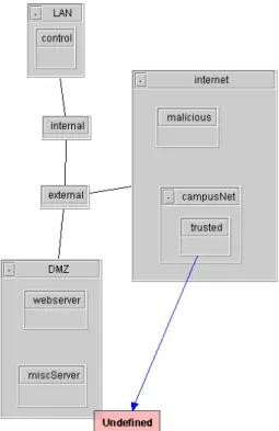
Arrows are coloured to represent different types of services. In the allowed view, unexpected arrows in the picture indicate that the firewall rules have allowed packets that should be discarded according to the se-curity policy. Conversely, the absence of an expected arrow indicates that a rule has incorrectly blocked ac-cess. In the example shown in Figure 2, web service is granted from localNet to webServer given that the colour of the arrow denotes TCP protocol on port 80. Recall that we also generate candidate packets based on the undefined IP addresses and services found in
Figure 2. Use of Arrow
Figure 3. Grouped structure
the firewall rule sets, therefore this information will be reflected in the picture as well. One extra color will be used to denote all the undefined services; each undefined IP Address will create an extra node on the picture, each node will be drawn near the network to which the IP address of the node belongs.
As the complexity increases, the picture will fill with crossed lines, boxes will be surrounded by arrow heads, nodes and edges may be forced to overlap, and so on. We have adopted a number of techniques to help reduce the clutter while retaining a holistic network view of the simulation results.
• Grouped structure. In our initial design, hosts were connected by edges pointing to the networks they attach to; subnetworks were connected by edges to their parent networks; and the root net-works that did not have a parent network were connected to the gateways. The picture turned out to be messy as the number of network entities in-creased because of the large number of edges. We therefore adopted the grouped structure shown in Figure 3.
As in the picture, hosts are located inside the net-works they attach to, and subnetnet-works are located inside their parent networks. Only root networks are connected to gateways. The networks that have child entities can be folded to make their de-scendants invisible. In this case, the folded node represents itself and all of its descendant entities. Consequently, the same type of arrows between one of the other entities and descendants of the folded network will now be combined. After the folded network is expanded, the arrows depicting service from the descendants entities will be re-7
stored. The fold/expand mechanism gives users the ability to examine the simulation result at different levels on the tree structure of the net-work while at the same time significantly reducing the line number if there are many nested network structures in the topology.
• Service filters. Numerous services are now being used in network applications, and firewall rule sets often have to deal with a variety of services. Al-though we evenly divide the color space to assign colors to services, too many service arrows between the same pair of entities might also make the in-spection difficult. We therefore introduced service filters that allow users to reduce visual clutter by filtering out services that they are not currently evaluating. An effective technique is to use the service filters to check services one at a time, fil-tering out the ones that are found to be error-free. This results in a display of only those services re-flecting configuration errors.
• Host/Network filters. These filters are completely analogous to service filters. Users can interactively remove portions of the network from the diagram in order to focus more clearly on specific parts.
4.3
Interaction
We have designed the views to be interactive with the goals of reducing the mental effort required to cor-rect configuration errors, and improving the accuracy of the corrections. After identifying suspicious arrows in the picture, users will want to locate the underlying rule set errors and quickly make appropriate changes with as little effort as possible.
In our visualization scheme, an arrow in the picture corresponds to packets that have been delivered from the source to the destination in the simulation. As per the discussion in Section 2, we believe that pre-senting only the executed rule (the first one that is matched) is not always enough for the administrator to understand the outcome. We therefore identify all the rules that could be matched by an arrow. When a packet arrives at a gateway and is being delivered to the next hop, we record all the possible matched rules. A click on an arrow will highlight those rules that could be matched by the packets associated with this arrow. Since a firewall will restrict packets from both directions, the highlighted rules will fall into two categories too, examples in Section 6 will show how we highlight the rules for restricting packets in both direc-tions. The rules are shown in an edit panel that allows in-place editing to correct them. Modifications can be
immediately verified by re-running the simulation and visually observing the impact.
5
Implementation
The prototype implementation of the tool was built using Java version 1.4.2. Two external packages were used in the implementation.
• Rhino: Rhino is a Java implementation of JavaScript version 1.5. It was created by the Mozilla project (www.mozilla.org/rhino) in antic-ipation of a Java based version of the Mozilla browser (an idea that was abandoned only af-ter the completion of Rhino). It provides access methods both from Java to JavaScript and vice versa. Therefore, Java code can be “scripted” in the Rhino shell, and JavaScript can be embedded into Java code where JavaScript objects can be directly referenced in Java code. We utilized this package to implement the description language parser so that the description file conforms with the JavaScript syntax.
• JGraph: JGraph is an open source graph draw-ing and layout component that is purely written in Java (www.jgraph.org). It provides the under-lying data model as well as visual presentation of a graph. It also takes care of some basic inter-action with the graph such as selecting, dragging and resizing graph nodes. The layout package in JGraph provides several well-known graph layout algorithms.
We used the JGraph package as the basis for our visualization module, though non-trivial extension and customization was necessary to fit our needs. For example, the presentation of a vertex was ex-tended to draw a grouped structure. Other major changes include extending the layout algorithm to make it support nested layout and the way that JGraph handles node selection.
6
Evaluation
To evaluate our application, we devised a realistic network topology that is typical of modern firewall con-figuration (see Figure 4). We classify the mistakes in rule set into three classes, each of which represents one type of mistake. We will describe the scenario and con-figuration errors first and then present how our tool reflects each class of errors.
The network topology of our example is shown in Figure 4. Two firewall rule sets are on the gateways
Figure 4. Network topology
Figure 5. Picture of typo mistake
named internal and external respectively. The security policy is as follows:
• Web services are allowed from anywhere to the web server.
• All machines on campus network can access the miscellaneous server using Telnet.
• Allow trusted hosts to access internal host control using SSH.
• Block all traffic from malicious hosts.
6.1
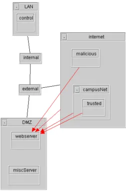
Typos
As we mentioned in Section 1, these errors are not hard to understand but easy to have. These errors will grant unwanted access so they are also critical. In this example, the first rule on gateway external specified the address of 111.222.1.2 as the FTP server address which is actually 111.222.1.3. In our simulation, a packet will be generated if there is an unrecognized IP address in the rule set, so the incorrect address 111.222.1.2 repre-sents some host within the DMZ. The picture is shown in Figure 5 According to the security policy, we expect that the arrow starts from the host trusted pointing to the miscServer whereas now it points to an extra node
Figure 6. Highlighted rules of typo mistake
sitting in the DMZ box. Clicking on that arrow will highlight all the rules that are related as in Figure 6. By examining the marked rules, we can easily discover that the mistake is a simple typo.
6.2
Overlap Error
Two rules overlap when each one of them matches some of the packets that match the other rule. When dealing with the packets that could match both rules, the first matched one in order decides the action. This is often trickier to discover than other types of mis-takes, especially when dealing with large or multiple rule sets. In the picture in figure 7, the first thing we see is that all the arrows are dashed lines. As we men-tioned in section 4.2.1, this implies that packets of web service are allowed in only one way. To correct this, we simply add the rule to allow TCP packets from web server to everywhere else. The corrected picture then shows the overlap error in figure 8. We should block all the TCP packets from the host malicious, hence the arrow from host malicious to host webserver is not ex-pected. The highlighted rules are shown in Figure 9. The problem is caused by the order of the second rule and the third rule. The second rule opens the web service to the entire Internet but the subsequent rule tries to block packets from a malicious host. The cor-rect order should be the reversed sequence of these two rules.
6.3
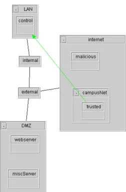
Masking error
A rule will not change the security policy if a preced-ing rule matches all the packets that match the masked
Figure 7. Picture of overlap mistake
Figure 9. Highlighted rules of overlap mistake
rule, we call it masked because its effects are masked. This type of mistake might be caused by adding rules to an existing rule set without realizing that the order makes an existing rule mask newly added ones.
In the example, we expect that all the machines from campusNet can use Telnet to access our internal host control. However, from inspection of the picture in Figure 10, we find that only the host trusted is allowed to do so. We can locate the mistake by clicking on the arrow. The highlighted rules in Figure 11 and in Figure 12 show the matched rules on two rule sets re-spectively. The rule on gateway external only permits SSH connections from the host trusted so that it masks the effect of the first rule on gateway internal that tries to permit SSH from network campusNet.
6.4
Results
Our tool reflected all three types of errors in a way that is easy to spot. All the errors can be made di-rectly within the tool and correctness can be verified immediately after modification in the same way.
Performance: For the example network described here, the simulation takes less than 2 seconds to com-plete on a standard PC with a 1.8 GHz CPU and 256 MB RAM.
7
Conclusions and Future Work
Even with contemporary tools, firewall configura-tion continues to be a difficult task. We have described a number of difficult issues, and proposed an
interde-Figure 10. Picture of mask mistake
Figure 11. Rules of mask mistake on gateway external
Figure 12. Rules of mask mistake on gateway internal
pendent set of techniques that we believe offer a good solution to some of the difficult problems. These tech-niques have been implemented in a prototype tool that involves administrators in an interactive exploration of firewall behaviour that closely reflects the network models and security policies that define how they think about the network. A simulation is used to discern the emergent behaviour of multiple, interacting fire-wall rule sets, and the results are displayed in a way that visually resembles the network topology. The vi-sual display is also linked back to the underlying rules to reflect the cyclic process of firewall configuration. We believe that this interaction style will reduce the mental effort needed to debug a complex rule set. We have conducted an analysis and informal evaluation to illustrate how the prototype tool exposes common con-figuration mistakes. Based on this evaluation, we be-lieve this to be a promising approach that has met our initial design objectives.
Future work will include:
• A more usable network entity description builder is needed for the first stage of simulation. The description language we designed here is time-consuming and not easy to specify. We envision that an intuitive GUI-based interface supporting drag-and-drop actions will go a long way toward simplifying the task.
• For now, we aimed only at checking the con-formance between security policy and rule sets whereas the security quality of configuration is not considered. That is to say, if the security policy is poor, our tool will not help. A module of security advisor which will make helpful suggestions on the configuration in terms of security can be added to our tool. Its function is similar to consulting an expert about security tips, e.g., what ports should be considered.
• We will carry out a more in-depth and thorough evaluation to evaluate our tool further. Our goal is to cope with scenarios where large scale network
topology and firewall rule sets are involved so that more complex cases will be tested. Other system-atic and formal ways of usability testing will also be taken into consideration.
References
[1] Check point visual policy editor data sheet. Avail-able on: http://www.checkpoint.com/products/ downloads/vpe\ datasheet.pdf.
[2] E. Al-Shaer and H. Hamed. Firewall policy advi-sor for anomaly detection and rule editing. In Proc. IEEE/IFIP 8th Int. Symp. Integrated Network Man-agement (IM 2003), pages 17–30, Mar. 2003.
[3] J. P. Anderson, S. Brand, L. Gong, T. Haigh, S. Lip-ner, T. Lunt, R. Nelson, W. Neugent, H. Orman, M. Ranum, R. Schell, and E. Spafford. Firewalls: An expert roundtable. IEEE Software, 14(5):60–66, Oct. 1997.
[4] D. Eppstein and S. Muthukrishnan. Internet packet filter management and rectangle geometry. In Proceed-ings of 12th Annual ACM-SIAM Symposium on Dis-crete Algorithms (SODA), pages 827–835, Jan. 2001. [5] P. Eronen and J. Zitting. An expert system for
analyzing firewall rules. In Proceedings of the 6th Nordic Workshop on Secure IT Systems (NordSec 2001), pages 100–107, Copenhagen, Denmark, Nov. 2001.
[6] A. Hari, S. Suri, and G. Parulkar. Detecting and re-solving packet filter conflicts. In Proceedings of IEEE Infocom, volume 3, pages 1203–1212, Tel Aviv, Israel, Mar. 2000.
[7] A. Mayer, A. Wool, and E. Ziskind. Fang: A firewall analysis engine. IEEE Symposium on Security and Privacy, page 177, May 2000.
[8] R. Oppliger. Internet security: firewalls and be-yond. Communications of the ACM, 40(5):92–102, May 1997.
[9] J. Wack, K. Cutler, and J. Pole. Guidelines on firewalls and firewall policy. NIST Recommendations, SP 800-41, Jan. 2002.
[10] A. Wool. A quantitative study of firewall configuration errors. IEEE Computer, 37(6):62–67, 2004.