Publisher’s version / Version de l'éditeur:
Vous avez des questions? Nous pouvons vous aider. Pour communiquer directement avec un auteur, consultez la première page de la revue dans laquelle son article a été publié afin de trouver ses coordonnées. Si vous n’arrivez pas à les repérer, communiquez avec nous à [email protected].
Questions? Contact the NRC Publications Archive team at
[email protected]. If you wish to email the authors directly, please see the first page of the publication for their contact information.
https://publications-cnrc.canada.ca/fra/droits
L’accès à ce site Web et l’utilisation de son contenu sont assujettis aux conditions présentées dans le site
LISEZ CES CONDITIONS ATTENTIVEMENT AVANT D’UTILISER CE SITE WEB.
Proceedings of the ESIM 2004 Conference: 10 June 2004, Vancouver, pp.
183-189, 2004-06-01
READ THESE TERMS AND CONDITIONS CAREFULLY BEFORE USING THIS WEBSITE. https://nrc-publications.canada.ca/eng/copyright
NRC Publications Archive Record / Notice des Archives des publications du CNRC : https://nrc-publications.canada.ca/eng/view/object/?id=7d48f951-0942-4ce3-9a65-077a9adca431 https://publications-cnrc.canada.ca/fra/voir/objet/?id=7d48f951-0942-4ce3-9a65-077a9adca431
NRC Publications Archive
Archives des publications du CNRC
This publication could be one of several versions: author’s original, accepted manuscript or the publisher’s version. / La version de cette publication peut être l’une des suivantes : la version prépublication de l’auteur, la version acceptée du manuscrit ou la version de l’éditeur.
Access and use of this website and the material on it are subject to the Terms and Conditions set forth at
Electric lighting energy savings for a photocell controlled dimmer - a
comparative simulation study using DOE.2 and Lightswitch Wizard
Reinhart, C. F.; Jones, C.
Electric lighting energy savings for an on/off photocell control – a
comparative simulation study using DOE2.1 and DAYSIM
Reinhart, C.; Jones, C.
NRCC-46761
A version of this document is published in / Une version de ce document se trouve dans :
Proceedings of eSim 2004, Vancouver, B.C., June 10-11, 2004, pp. 183-189
ELECTRIC LIGHTING ENERGY SAVINGS FOR AN ON/OFF PHOTOCELL
CONTROL – A COMPARATIVE SIMULATION STUDY USING DOE2.1 AND DAYSIM
Christoph F. Reinhart
The Lighting Group - Institute for Research in Construction
National Research Council Canada, Ottawa K1A 0R6, Canada
[email protected]
Christopher Jones
EnerSys Analytics Inc.
Toronto, Ont., M5J 2E6, Canada
[email protected]
ABSTRACT
This paper suggests a method how to predict electric lighting energy savings for photocell controls in daylit spaces taking manual blind control into account. The method predicts lower but supposedly more “realistic” lighting energy savings than conventional simulation approaches. On the other hand, predicted savings are larger than those predicted by ASHRAE 90.1 power adjustment factors. The method is demonstrated in a hypothetical open plan office in Calgary, Canada. A comparative simulation study is presented using DOE.2 and the RADIANCE-based daylighting analysis tool DAYSIM. Simulation results were found to differ substantially between DOE2 and DAYSIM even in the absence of venetian blinds. These discrepancies were attributed to the underlying simulation algorithms and sky models. Despite these differences, both simulation programs yielded energy savings more than twice the static 10% allowed for by ASHRAE 90.1 power adjustment factors for on/off control.
INTRODUCTION
Daylight has been identified by Pacific Gas & Electric as “the single largest ´new´ opportunity for saving energy in commercial lighting today” (Turnbull and Loisos 2000). On the other hand, there has been resistance to the allowance of daylighting credits in building codes and regulations based on the argument that savings cannot be guaranteed. This skepticism towards daylighting is partly the result of overoptimistic (and therefore never achieved) claims for daylighting energy savings that are frequently made based on daylight simulations. One contributing factor to unrealistic daylight saving predictions is that there currently is no widely used guideline on how to estimate the impact of manually operated shading devices on lighting energy savings. The lack of such a
guideline is surprising as a recent survey on the use of daylight simulation tools during building design identified shading type and control as the “most common design aspect influenced by a daylighting analysis” (Reinhart and Fitz, 2004). This suggests that in the absence of a standard procedure, designers have to develop their own approaches on how to identify a suitable shading device and control strategy for a particular design.
ASHRAE Standard 90.1-1989 offered a simple method to account for energy savings of lighting controls compared to no controls. When the standard was revised in 1999, the lighting control credits were eliminated. Nevertheless, they are still routinely referred to in the absence of something better. Section 6.4.3 of the 1989 version of the standard provides for lighting power allowance adjustments if automatic lighting controls are used in a space. For daylighting, the power adjustment factors (PAF) are listed in Table 1.
Table1: Power Adjustment Factor (ASHRAE 90.1-1989)
Lighting Control PAF
Continuous Dimming 30 % Multiple Step Dimming 20 % On/Off Control 10 %
A PAF corresponds to the percentage by which the connected lighting load can be reduced to account for the lighting energy saved by the lighting controls. The PAF method does not take building geometry, orientation, space usage or shading type and control into account, i.e. it provides a conservative, static savings estimate that does not reward innovative daylight design. The PAF method has been adopted by the Canadian Commercial Building Incentive Program (CBIP) for simulations using the EE4 software. Through CBIP, Natural Resources Canada offers financial incentives for the incorporation of energy
efficiency features in new commercial/institutional building designs.
This paper suggests a method how to predict electric lighting energy savings taking interior illuminances and manual blind control into account. A comparative simulation study of electric lighting energy savings from an on/off photocell control is presented using DOE.2 (Winkelmann 1983) and DAYSIM (Reinhart and Walkenhorst 2001). The two programs have been chosen as they predict energy savings due to lighting controls based on indoor illuminances and manual blind control. Following a review of the underlying daylight simulation algorithms and blind models in DOE2.1E and DAYSIM, simulation results are presented for both programs for an example open plan office building in Calgary, Canada. The analysis discusses differences between simulation results and proposes a simple method how to yield realistic energy saving predictions for an on/off photocell control.
UNDERLYING MODELS
This section reviews the daylight simulation algorithms and blind control models that are used by DOE2E.1 and DAYSIM.
Daylight simulation algorithms
Both simulation programs require a pre-simulation calculation to effectively model indoor illuminances at each time step during a simulation run.
During a DOE.2 pre-simulation, a set of 21 “daylight factors” is calculated for each investigated sensor point under CIE sunny and overcast sky conditions using the split-flux method (Hopkins et al. 1996). During the actual annual simulation hourly indoor illuminances are interpolated from the 21 daylight factors – using cloud cover and sun position data at each time step.
During a DAYSIM pre-simulation, a set of some 212 “daylight coefficients” is calculated for each sensor point using the RADIANCE algorithm (Ward and Rubinstein 1988). During the annual calculation these daylight coefficients are combined at each time step with the sky luminous distribution according to the Perez all weather sky model (Perez et al. 1993).
A recent comparison of different dynamic daylight simulation approaches yielded that simulations based on the CIE overcast sky model tend to underestimate celestial luminances near the horizon, which can in turn lead to too low interior illuminance predictions (Reinhart and Herkel 2000).
Blind Control Models
A common approach is to express daylight energy savings for lighting and blind controls with respect to a permanently activated lighting system without any blinds (Szerman 1996, Ullah and Lefebvre 2000, Bodart and De Herde 2002). This approach neglects that shading devices are a necessity in most offices to control direct sunlight. Energy savings predicted by this approach correspond to an upper limit of how much electric lighting energy could theoretically be saved with an ideally commissioned lighting system if direct sunlight did not bother occupants. Real energy savings will be somewhat lower. Such approaches lead to the overoptimistic savings mentioned in the introduction.
Modeling blinds requires two steps: the ability to model interior illuminances when the blinds are drawn and to predict the status of the blinds throughout the year.
In DOE2.1E, venetian blinds are modeled as perfect diffusers, i.e. translucent materials that uniformly scatter transmitted light in all directions. Obviously “a translucent shade is closer to being a perfect diffuser than venetian blinds” (Winkelmann 1983). The RADIANCE algorithm used by DAYSIM can model more accurately complex daylighting systems such as venetian blinds and laser cut panels (Greenup et al. 2000). As detailed shading device simulations can be extremely time consuming, a simplified venetian blind model has been implemented into DAYSIM that can be used during schematic design. This simplified model assumes that venetian blinds are adjusted to a slat angle that blocks all direct sunlight and transmits 25% of all incoming diffuse daylight (Vartiainen 2000). The assumption is supported up by the observation that blinds are usually lowered to avoid direct glare and overheating (see below).
The second step is to predict the blind status throughout the year. Most models assume that manually controlled shading devices are always either being fully closed or opened. They are closed by the occupant when a glare criteria is met or if the space becomes overheated. Privacy needs have also been observed to trigger the closing of blinds but are currently not considered by models (Reinhart and Voss 2003). In DOE2.1E glare is assumed in the presence of transmitted direct solar radiation above 94.5 Wm-2 or a Hopkins glare index above 20 (Lee and Selkowitz 1995). In DAYSIM blinds are closed if transmitted direct sunlight above 50Wm-2 is incident on the work plane. The models also differ as to when the shading device is opened again by the occupant. In “ideal blind control” mode DOE2 assumes that the shading device
is opened as soon as glare and overheating are no longer met. In “active blind control” DAYSIM assumes that the shading device remains lowered until the occupant’s arrival on the next working day. The justification for the conservative approach in DAYSIM is a Japanese field study that observed a tendency for blinds to remain closed in the afternoon even when solar radiation levels had fallen substantially below the glare criteria (Inoue et al. 1994).
METHOD
Simulations were run for a hypothetical open plan office located in Calgary, Canada (N 51.12o, W 14.02o).
Building Description
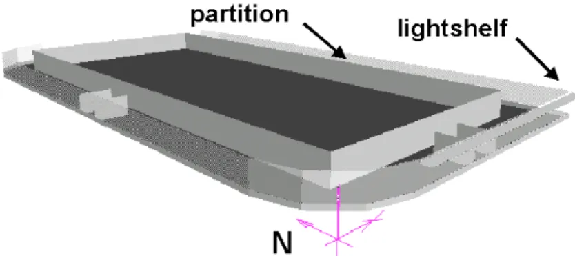
The building had a footprint of 65 m x 36.3 m. Figure 1 shows a visualization of a typical floor of the building. The windows were essentially fully glazed around the entire face of the building ranging from 0.475m to 2.75m above the floor. The glazings were double pane with a visual transmission of 61%. The floor-to-ceiling height was 2.8m. The South facade had an external lightshelf at 0.2m below the top of the window. The lightshelf extended 1.2m out from the face of the window and was modeled with a diffuse reflectance of 60%. Reflectances of the ceiling, internal partitions and floor were 80%, 50% and 20%, respectively. Partitions surrounding peripheral workstations were 2.1m high. Obstructions due to surrounding buildings or landscape were not considered. Office hours were weekdays between 7.00 and 18.00.
The perimeter, daylit zones were 3.6 m wide around the entire floor. The electric lighting in these zones was provided by fluorescent fixtures, controlled with on/off ballasts by photocells in the perimeter spaces. One photocell per facade was centrally ceiling mounted, at 1.8 m in from the facade. The overall lighting density in the daylit zones was 9.36 Wm-2. The required minimum illuminance threshold in the perimeter zone was 600 lux (60 foot candles) at work station height during office hours. Shading was
provided through manually operated venetian blinds at each perimeter workstation (shading coefficient in DOE2 33%).
Figure 1: RSHOW visualization of the model.
DAYSIM/RADIANCE
Objective of Daylight Simulations
The objective of the daylight simulations was to quantify the electric lighting energy savings of the on/off photocell control compared to a reference lighting system that was permanently activated during occupied hours.
Simulation Assumptions
Photosensor control: The lights in all perimeter work stations sharing the same facade were on/off controlled by the photocell located in the center work station of the facade. DOE2.1E and DAYSIM both assumed an ideally commissioned photocell that turned off the lights when the desktop illuminance from daylight directly below photocell was above 800 lux. The extra 200 lux compared to the 600 lux required minimum illuminance level were added to allow for imperfections of a real lighting control system and to account for the fact, that the illuminances at other workstations in the same zone might lie below those in the central workstation with the photocell.
Weather Data: DOE2.1E and DAYSIM both used the CWEC weather data for Calgary available for download from the US Department of Energy web site
www.eere.energy.gov/buildings/energyplus/weatherdata.html
. While DOE2.1E simulations were using a one hour time step, DAYSIM simulations were based on 5 minute time steps.
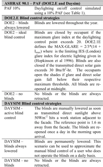
Blind Control: Apart from the dynamic manual blind controls discussed above, DOE2.1E and DAYSIM also allow the blinds to be set in a fixed position throughout the year. Table 2 describes the blind control scenarios that have been modeled in the two programs.
RESULTS AND ANALYSIS
Figure 2 shows the predicted electric lighting energy use in the four perimeter zones for the different scenarios in Table 2.
Both the reference case (no controls) and the PAF predictions are independent of the considered facade orientation.
Both for DOE2 and DAYSIM energy savings are highest in the absence of blinds, followed by dynamic blind use (DOE2 - ideal blind control and DAYSIM - active blind control) and “blinds always lowered”. This consistency within the programs is expected. What is disconcerting are the large absolute differences between the two programs. Predicted energy use in the absence of blinds is nearly twice as
big for DOE2 as for DAYSIM. This reveals that DAYSIM predicts higher interior illuminances than DOE2. The discrepancy results from the different underlying dynamic daylight simulation approaches used by the two programs.
Table 2: Investigated Scenarios
Reference Case (DOE2.E and Daysim)
Reference Case No daylighting controls. The electric lighting is permanently activated on weekdays between 7.00 and 18.00. ASHRAE 90.1 – PAF (DOE2.E and Daysim)
PAF 10% Daylighting on/off control simulated using a 10% PAF (see Table 1).
DOE2.E Blind control strategies DOE2 – blinds
always lowered
Blinds are lowered throughout the year. DOE2 – ideal
blind control
Blinds are closed by occupant if the maximum glare index at the daylighting control point exceeds 20. DOE2.1E defines the MAX-GLARE = 2/3*(14 + Imax) where is the limiting IES (London)
glare index for electric lighting given in (Hopkinson et al 1996). Blinds are also closed if the transmitted direct solar gain exceeds 30 Btu/ft2-hr. The occupants open the shades if glare and direct solar gain fall below their respective maximum thresholds. All blinds are re-opened at midnight.
DOE2 – no blinds
No blinds or the blinds are always retracted.
DAYSIM Blind control strategies DAYSIM -
active blind control
The blinds are manually lowered as soon as transmitted direct sunlight above 50Wm-2 hits a work station adjacent to the facade. The reference point is 1.6 m away from the facade. The blinds are re-opened once a day in the morning upon arrival.
DAYSIM – blinds always lowered
Blinds are permanently lowered: This scenario can be used to approximate the manual blind control of a user who does not operate the blinds on a daily basis. DAYSIM – no
blinds
No blinds or the blinds are always retracted.
Given that DOE2 predicts lower illuminances than DAYSIM in the absence of blinds, it is surprising to note that the reverse is true for “blinds always lowered” scenarios. The reasons for this is that DOE2 treats venetian blinds as an ideal diffuser with a transmission of 33% for direct and diffuse daylight. In contrast, DAYSIM assumes that the blinds block all direct sunlight and transmit only 25% of diffuse daylight.
The simulation results for the two dynamic blind scenarios tend to lie closer to the “no blinds” scenarios than the “blinds always lowered” scenarios revealing that even though the blinds are regularly used to avoid glare, they are still opened sufficiently often to admit “glare-free” daylight into the building. In DAYSIM the blinds are nearly always retracted for the North facade as direct sunlight rarely hits the workstations. The opposite happens on the Eastern facade. As the DAYSIM model assumes that the blinds once closed remain so for the remaining of the working day, the blinds on this facade are closed most of the year.
Predicting realistic energy savings
Despite the variety of simulation results generated by DOE2 and DAYSIM in Figure 2, it is encouraging that all scenarios except “DAYSIM – blinds always lowered” on the North facade yield higher energy saving predictions than the PAF methods.
How can the results in Figure 2 be interpreted to get a realistic energy savings estimate for the on/off photocell control? As discussed above, the “no blinds” scenarios can be discarded as being unrealistic. The “blinds always lowered and “ideal/active blind control” represent two extreme user behaviors that result in an upper and a lower limit of how much energy savings can be realistically expected in the offices. In the nomenclature of DAYSIM, these two blind control models describe a “passive” and an “active” user. The final energy use in the building should lie somewhere in between these two extremes, the actual number depending on how many perimeter occupants are active or passive types. During building design this ratio is obviously unknown. Assuming an unbiased occupant sample, a simple engineering approach is to assume that the building will be occupied by a equal number of both users types. Therefore the resulting mean electric
Figure 2: Predicted annual electric lighting energy use in the four perimeter zones for the scenarios in Table 2. The scheduled electric lighting is activated on weekdays from 7.00 to 18.00. With the exception of the reference case, a photocell switches the lighting
lighting energy use in the building should be close to me
s are more than twice as
igh as the PAF predictions. the an of the two scenarios.
Figure 3 shows the results from Figure 2 interpreted accordingly. Both programs with the exception of the DAYSIM East facade predict energy savings of over 40% for the photocell control. DAYSIM East predictions are only 23% as the blind model predicts that active users keep their blind closed most of the day. All prediction
h
off when the work plane illuminance from daylight below the cell is above 800 lux.
DISCUSSION AND CONCLUSIONS
The following discussion addresses the capabilities of nances and energy savings due to lighting controls.
DOE2 and DAYSIM to predict interior illumi
Daylight simulations using DOE2 and DAYSIM
The previous section has shown that interior illuminan
Figure 3: Predicted annual electric lighting energy use in the four perimeter zones using power adjustment factors (PAF ), DOE2, and DAYSIM. The lighting is activated on weekdays from 7.00 to 18.00 and the photocell switches the lighting off when the work plane illuminance from daylight below the sensor is above 800 lux.
ce predictions in DOE2 and DAYSIM differ substantially. These differences could be attributed to the underlying algorithms and models.
Which results are more reliable? DAYSIM simulation results for “no blinds”, relying on the RADIANCE simulation algorithm and the Perez sky model, can be expected to be more reliable than the cruder DOE2 daylight factor approach. When it comes to modeling static daylighting systems such as light shelves or laser cut panels, DAYSIM will also yield more reliable results than DOE2. This statement is not necessarily true for venetian blind systems. While DAYSIM/RADIANCE can accurately model venetian blinds, the uncertainty as to how users adjust the slat angle is shared by both approaches. Therefore, even if DAYSIM can in principle model interior illuminances correctly, this advantage over DOE2 might be offset when it comes to modeling adjustable shading devices such as blinds. Nevertheless, even the simplified blind
model used in DAYSIM that blocks direct sunlight can be expected to yield more realistic, lower illuminance
redic
y uses resulting from these two nd c
is sults could be expected, as the annual amount of
ylig
ast and West facades. On the North facade,
l” assumed on a typical day in May that the occupants
set t
n those zones where the blinds are drawn. To the authors’ knowledge there
no
While it remains uncertain
co pes in daylit
• ving predictions than the ones currently
eantime, using the method should lead to more realistic saving predictions and help to overcome the reputation of lighting controls to p tions than the ideal diffuser approach in DOE2.
Modeling manual blind control
A key element in both programs is that they are capable of simulating dynamic blind use and static blind use with the blinds permanently lowered. The mean of the two energ
bli ontrol scenarios should yield a superior estimate to the ASHRAE 90.1 power adjustment factors or the “no blinds” scenario.
In the hypothetical building the resulting savings were higher than the PAF allowance. Th re
da ht in the perimeter zones was large with a daylight factor near the work stations of around 6%.
Which simulation program yields more reliable results? This question cannot be answered without further field measurements. The blind closing criteria in DOE2 and DAYSIM lead to comparable results for the South, E
the DOE2 algorithm is more conservative as the glare index criteria can be met in the absence of direct sunlight.
On the other hand, the opening algorithm in DAYSIM is more conservative than the one in DOE2. Opening the blinds as soon as the glare criteria is no longer met requires a high degree of attentiveness of the user to the outdoor conditions (even when the blinds are closed) and is therefore “highly optimistic” (Lee and Selkowitz 1995). A closer analysis of the DOE 2 results showed that “ideal blind contro re heir blinds six times. It is doubtful that real occupants would open and close the blinds as often.
Both programs are ultimately optimistic, as they consider ideally functioning lighting systems in all perimeter work stations. In a real building the occupant below the photocell might frequently keep the blinds up (active type) while his or her colleagues sharing the same facade might prefer their blinds lowered (passive type). In such a situation the photocell regularly detects more than 800 lux at the central workstation and switches the lighting off for the whole facade which might result in user complaints i
is reliable way to sidestep this problem except by adding more photocell controls.
Summing up, the proposed method to estimate more realistic energy saving predictions for on/off controls could be successfully applied to DOE2 and DAYSIM simulations.
which program yields more accurate results, using the ncept of active and passive user ty
spaces should result in: smaller sa
predicted by simulation programs, but
• larger predictions than allowed for by the static PAF method.
There is an obviously need for more research into the interaction of building occupants with lighting and shading controls. In the m
be “under-performers”.
ACKNOWLEDGEMENTS
This work has been funded by the National Research Council Canada and Natural Resources Canada under B-3213 and by EnerSys Analytics the contract number
Inc.
REFERENCES
Bodart M, De Herde A (2002) Global Energy Savings
Compagnon R (2000), RADIANCE algorithm to simulate laser-cut panel
opment of an optimal control system for window shading devices based on
tegrated envelope and lighting control strategies for commercial buildings. ASHRAE
eals R, and Michalsky J (1993), All-Weather Model for Sky Luminance Distribution - Preliminary
he Simulation of
O (2001), Dynamic in Office Buildings by the Use of Daylighting. Energy
and Buildings 34, 412-429.
Greenup P, Edmonds I R,
light-redirecting elements, Lighting Research and
Technology 32(2) pp. 49-54.
Hopkinson R G, Petherbridge P, Longmore J (1996),
Daylighting, Heinemann, London, p. 306.
Inoue T, Kawase T, Ibamoto T, Takakusa S, and Matsuo Y (1998), The devel
investigations in office buildings. ASHRAE
Transactions 104, 1034-1049.
Lee E S and Selkowitz S E (1995), The Design and Evaluation of in
Transactions, Chicago, Il 101[1], 326-342. January
28-February 1. Perez R, S
Configuration and Validation. Solar Energy 50[3], 235-245.
Reinhart C F and Herkel S (2000), T
Annual Daylight Illuminance Distributions- A state of the art comparison of six RADIANCE-based methods. Energy & Buildings 32[2], 167-187.
RADIANCE-based Daylight Simulations for a full-scale Test Office with outer Venetian Blinds. Energy
and Buildings 33[7], 683-697.
Reinhart C F, Voss K (2003), . Monitoring Manual Control of Electric Lighting and Blinds. Lighting
Research and Technology 35[3], 243-260..
Reinhart C F, Fitz A (2004), Key findings from a
Szerman M (1996) Auswirkungen der
aylighting, Conf. Proc. of
xperience with Weather Data for Simulation and Design, Part 1:
.
ineering Society 1, 80-91.
inkelmann F C. (1983), Daylighting Calculation in OE2, LBNL Report #11353, Applied Science Division,. May 1983.
survey on the use of daylight simulation programs,
Conf. Proc. of the ESIM 2004 Conference, Vancouver,
June 2004.
Tageslichtnutzung auf das energetische Verhalten von Bürogebäuden. Bauphysik, No. 4, pp. 97 - 109 and No.5, pp. 149 -156.
Turnbull P, Loisos G (2000), Baselines and Barriers: Current Design Practices in D
the ACEEE 2000 Summer Study on Energy Efficient Buildings, Pacific Grove, California, USA, August 20th
–25th 2000, pp. 3.329 – 337
Ullah M B, Lefebvre G (2000) E
Estimation of Annual Energy-Saving Contribution of an Automated Blind System. ASHRAE Transactions: Symposium Papers 106[2], 408-421.
Vartiainen, E (2001), Electricity benefits of daylighting and photovoltaics for various solar facade layouts in office buildings. Energy and Buildings 33, 113-120 Ward G and Rubinstein F. (1988) A New Technique for Computer Simulation of Illuminated Spaces. Jour.
of the Illuminating Eng
W D