Publisher’s version / Version de l'éditeur:
International Journal of Architectural Heritage, 1, July 3, pp. 293-310, 2007-07-01
READ THESE TERMS AND CONDITIONS CAREFULLY BEFORE USING THIS WEBSITE.
https://nrc-publications.canada.ca/eng/copyright
Vous avez des questions? Nous pouvons vous aider. Pour communiquer directement avec un auteur, consultez la
première page de la revue dans laquelle son article a été publié afin de trouver ses coordonnées. Si vous n’arrivez pas à les repérer, communiquez avec nous à PublicationsArchive-ArchivesPublications@nrc-cnrc.gc.ca.
Questions? Contact the NRC Publications Archive team at
PublicationsArchive-ArchivesPublications@nrc-cnrc.gc.ca. If you wish to email the authors directly, please see the first page of the publication for their contact information.
Archives des publications du CNRC
This publication could be one of several versions: author’s original, accepted manuscript or the publisher’s version. / La version de cette publication peut être l’une des suivantes : la version prépublication de l’auteur, la version acceptée du manuscrit ou la version de l’éditeur.
Access and use of this website and the material on it are subject to the Terms and Conditions set forth at
Measurement methods of moisture in building envelopes - a literature
review
Said, M. N.
https://publications-cnrc.canada.ca/fra/droits
L’accès à ce site Web et l’utilisation de son contenu sont assujettis aux conditions présentées dans le site LISEZ CES CONDITIONS ATTENTIVEMENT AVANT D’UTILISER CE SITE WEB.
NRC Publications Record / Notice d'Archives des publications de CNRC: https://nrc-publications.canada.ca/eng/view/object/?id=4c9e497c-5a75-4603-b01e-c1385bede194 https://publications-cnrc.canada.ca/fra/voir/objet/?id=4c9e497c-5a75-4603-b01e-c1385bede194
M e a s u r e m e n t m e t h o d s o f m o i s t u r e i n b u i l d i n g
e n v e l o p e s – a l i t e r a t u r e r e v i e w
N R C C - 5 0 0 3 9
S a i d , M . N .
A version of this document is published in / Une version de ce document se trouve dans: International Journal of Architectural Heritage, v. 1, no. 3, July 2007, pp. 293-310
The material in this document is covered by the provisions of the Copyright Act, by Canadian laws, policies, regulations and international agreements. Such provisions serve to identify the information source and, in specific instances, to prohibit reproduction of materials without written permission. For more information visit http://laws.justice.gc.ca/en/showtdm/cs/C-42
Les renseignements dans ce document sont protégés par la Loi sur le droit d'auteur, par les lois, les politiques et les règlements du Canada et des accords internationaux. Ces dispositions permettent d'identifier la source de l'information et, dans certains cas, d'interdire la copie de documents sans permission écrite. Pour obtenir de plus amples renseignements : http://lois.justice.gc.ca/fr/showtdm/cs/C-42
M. Nady A. Saïd,
Ph.D., P.Eng.National Research Council Canada, Ottawa, Ontario, K1A 0R6 Canada Email: nady.said@nrc.gc.ca
ABSTRACT
This article reviews the methods, principles, and performances of moisture measurement
in building envelopes with a focus on continuous monitoring applications. It compiles an
extensive list of closely related literature. Brief examples are presented to demonstrate
measurement values and a presentation approach for measured electric-resistance data.
Moisture measurement methods have various capabilities. Some methods can quantify
moisture content for some building materials such as timber, while also providing
comparative values or changes in wetness conditions for other building materials. Other
methods are used to warn of excessive wetness conditions in the envelope, particularly in
hidden or difficult-to-access areas. Reviewed methods are grouped according to the
measurement principle: for example, resistance, voltage, and thermal-based methods.
Resistance and voltage-based sensors are most suitable for continuous monitoring
applications as they can be readily connected to a data logging system. Voltage-based
methods such as the Sereda and printed circuit sensors are usually used to indicate
time-of-wetness of surfaces. Their main weakness is durability, which can be quite short in
outdoor applications. Resistance-based methods, such as moisture pins, Duff sensors, and
ceramic sensors, are used to monitor changes in moisture level within materials as well as
time-of-wetness of surfaces. These sensors are durable and can be fabricated in-house.
Keywords: moisture, time-of-wetness, sensors, measurements, building envelope, literature
review.
1. INTRODUCTION
Moisture measurement is used to investigate moisture issues in building envelopes. Moisture sensors and a data-logging system are used in continuous monitoring applications. Moisture sensors and an alarm system are used to warn of excessive moisture conditions in building envelopes, particularly in hidden or difficult-to-access areas. Non-destructive moisture diagnostic methods such as moisture meters and infrared thermography are usually used to identify areas with moisture anomalies in building envelopes, which might be followed with an invasive investigation and/or continuous monitoring to further investigate moisture anomalies. Moisture meters are also used to conduct periodic measurements at specified locations.
This article reviews methods, principles, and performances of moisture measurements in building envelopes with a focus on continuous monitoring applications. The article also compiles closely related literature to be easily accessed by professionals as considerable literature exists
Measurement methods of moisture in building envelopes may be grouped according to the measurement principle (e.g., resistance, voltage, thermal) or function. Resistance-, voltage-, and capacitance-based methods utilize the electrical properties of materials that vary with the material's moisture content (MC) or surface wetness. Microwave-based methods work on a principle similar to the capacitance methods, but at much higher frequencies (Dill 2000).
Thermal-based methods utilize the change in temperature of materials caused by the change in moisture conditions. Moisture creates temperature depressions in materials because of the high thermal capacity of water. A wet material has a lower temperature than when it is dry. Moisture flowing through materials in the building envelope assembly cools surfaces by direct contact and evaporation. Thermal-based methods are usually used in special tests and in soil moisture measurement applications; therefore, they are beyond the topic of this article.
Attempts have been made to use infrared thermography to identify areas of moisture anomalies in building envelopes (e.g., Gayo et al., 1993a and 1993b, Rosina and Robison 2002, Rosina and Spodek 2003). Infrared thermography techniques, similar to thermal-based methods, detect temperature changes caused by the presence of moisture. The main advantage of
thermography is the ability to assess moisture conditions over a large area of the building envelope. Thermographic scans must be made under appropriate environmental conditions and interpreted by qualified professionals. Geary (1970) reviews measurement methods of moisture in materials including infrared thermography, thermal, microwave power absorption, optical, and nuclear methods.
Resistance and voltage-based methods are most suitable for continuous monitoring applications as they can be readily connected to a data-logging system. These methods are reviewed in this article.
2.1. Resistance-Based Methods
Resistance-based methods measure moisture levels in materials in terms of their electric resistance or dielectric property that vary with MC. As MC increases, the material's electrical resistance decreases and conductance increases. The resistance could vary between several hundred k when wet to more than several hundred M when dry. Examples of resistance-type moisture sensors include moisture-pins, brick-ceramic, stone, Duff probe, moisture-measuring dowel and disc, nicked-wire, and moisture-detection tape/cable.
2.1.1. Moisture-Pin Sensor: Figure 1 shows various types of moisture-pins: (A) insulated pins,
(B) non-insulated pins, and (C) a pair of stainless-steel screws. Insulated pins are most common - these probes are approximately 3 mm diameter and are insulated except at the needlepoint tip.
A B
C
Figure 1. Various moisture-pins sensors: insulated pins (A), non-insulated pins (B), and stainless-steel screws (C) with a heat-shrinkable tubing covering part of its length. Shown at the top is a pair of insulated moisture pins inserted in a wood block.
As an alternative to commercial moisture pins, a pair of stainless-steel screws of the required length could be used. Heat-shrinkable tubing is used to cover the length of the screw that extends outside the material being monitored. The author has used stainless-steel screws
extensively in monitoring moisture conditions in masonry walls because stainless-steel screws provide good grip in mortar applications.
Moisture-pin probes measure moisture by measuring the electrical resistance of the material between the two probes (or between the tips of the probes for the insulated pins). This approach makes measured resistance dependent on the dielectric property of the material being measured in addition to a possible temperature effect. Moisture pins can quantify MC for various timber species with accuracy ±2% (Garrahan 1988). For other materials, moisture pins provide comparative moisture profiles indicating changes in MC of the material.
From the author's field experience, moisture-pin sensors are durable and respond quickly to changes in wetness conditions of the material. For timber applications, temperature
adjustments are necessary because changes in temperature affect the dielectric properties of timber. James (1975 and 1994), Garrahan (1988), Pfaff and Garrahan (1985), and the U.S. Forest Products Laboratory (FPL) (1982) report correction factors for timber species. These correction factors were developed for probe-type moisture meters.
Electric resistance output of moisture pins can be measured directly or indirectly in terms of a voltage. Figure 2 shows an electric circuit diagram used by the author for converting electric resistance to voltage output. To minimize errors due to the effect of polarization and electrolysis at the electrodes, the excitation voltage applied to the sensor is preferred to be an alternating voltage (2.5 volts is used). For moisture measurement in concrete materials, Altmann (1974) recommended using 12 volts alternating current (AC), and used Equation 1 to correlate measured electric resistance (R) with concrete MC (f):
Ln (R) = a – b • f
(1)
Where a and b are coefficients that depend on the material and are determined by calibration. Equation 1 gives a straight line on a semi-logarithmic scale.
Where:
Vo is measured output voltage
Rf is a fixed resistor for output signal (usually about 10 kΩ)
Rg is a fixed resistor in parallel with the moisture sensor (about to 10 MΩ)
Rm is the resistance output of the moisture sensor, which is calculated by:
Rm = Rf / [(Vo/(1-Vo) – Rf / Rg]
Figure 2. Electric circuit diagram to convert electric-resistance to voltage measurements.
Forrer and Vermaas (1987) used a direct current (DC) voltage with low-frequency alternating polarity and presented detailed analysis of electrical resistance measurements in terms of voltage. The authors developed an equation correlating resistance and temperature-corrected MC. Hedlin (1965) developed a logarithmic plotting technique and an empirical equation for resistance-based humidity sensors.
As a variation of moisture-pins sensor, Cunningham (1985) proposed a method for measuring timber MC over the range 10% to 50% using 10 mm square gold-plated parallel plates, which are embedded in the timber. Cunningham's motive was that timber MC above the range 25% to 30% could not be measured reliably using the DC electric resistance property of timber because it is almost constant in this range in addition to the possible polarization effect on measurements. Cunningham measured the DC electric resistance across the plates for MC below 30% and measured the AC impedance for MC above 25%. In the overlap range 25% to 30% MC, the weighted mean of the DC and AC measurements was used to determine the MC. Cunningham correlated measured results, MC and impedance or resistance by the following equations.
For AC measurements:
B
m
A
Z
Z
−
∞=
•
−
1
25
≤ m ≤ 50
(2)
Where Z is the probe AC impedance (ohms); m is MC (% by weight); and A, B, and Z∞ are the
correlation parameters. For DC measurements: n
m
D
C
R
)
=
+
(
log
1010
≤ m ≤ 30
(3)
Where R is the probe resistance (ohms); C, D, and n are the curve fitting parameters.
Cunningham (1985) determined the correlation parameters at 5ºC and 20ºC as noted in Table 1.
Table 1 Correlation parameters at 5°C and 20°C for Equations 2 and 3a Equation 2 (25 ≤ m ≤ 50) Equation 3 (10 ≤ m ≤ 30)
A B Z∞ C D n
5ºC 1.24 x 10⁻⁵ 2.71 x 10⁻⁴ 1.2 x 10⁴ 4.52 8.17 x 10³ 3 20ºC 1.28 x 10⁻⁵ 2.95 x 10⁻⁴ 8 x 10³ 1.98 79.3 1
aCunningham (1985).
2.1.2. Brick-Ceramic and Stone Moisture Sensors:
Brick-ceramic- (called ceramic here, for brevity) and stone-moisture sensors measure moisture indirectly by measuring the electric resistance across a small block of ceramic or stone material. This type of sensor, and generally sensors that utilize a small block of a material, eliminates the effects of the dielectric property of the material being monitored. The electrical resistance of the ceramic and the stone materials decreases as wetness increases and vice versa. The sensors are fabricated by attaching two wires to the opposite sides of a ceramic or stone block (Figure 3 shows typical dimensions) using conductive silver epoxy. The ceramic block is usually cut from a clay brick and the stone block is cut from a stone material similar to that of the wall to be monitored.The ceramic and stone sensors have been used extensively by the author and are
fabricated in-house. The ceramic sensor is usually used in surface mount applications to monitor time-of-wetness (TOW) of surfaces. The sensor could also be embedded in a material to
determine changes in its MC. The small size of the stone sensor allows it to be embedded in masonry walls through the usual 10 mm mortar joint. The ceramic and stone sensors are quite durable and respond quickly to changes in wetness conditions of surfaces or materials.
The temperature effect on measured electric resistance remains to be determined in a laboratory study. At temperatures below freezing, the output from the moisture sensors is not valid because the formation of ice increases the measured resistance, which leads to the erroneous results of dry conditions. Salts dissolved in moisture lower measured resistance.
(a) Brick-ceramic moisture sensor (b) Stone moisture sensor
Figure 3. Photographs and schematic illustrations showing the typical size of (a) brick-ceramic
and (b) stone moisture sensors used by the author in field measurements.
2.1.3. Duff Probe Moisture Sensor:
Duff (1966) describes the probe fabrication and lists data for MC versus electric resistance of the sensor. The Duff probe consists of two wires
attached with conductive silver epoxy to opposite sides of a wood block 2 mm square and 20 mm long. Duff noted that the sensor could be fabricated in various sizes. The wood block is selected such that it has a straight and close-grained structure to minimize interprobe variations. Sugar maple, yellow birch, and American beech have been used to fabricate sensors.
The Duff probe, as the ceramic and stone sensors, measures MC indirectly by measuring the resistance across the wooden block that is in equilibrium with the humidity of the surrounding environment. The probe could be used in a surface mount to indicate TOW or embedded in materials to monitor changes in MC. The probe measurements require temperature corrections for the effect of temperature on the probe's electric resistance. Correction factors for timber species noted earlier such as by Garrahan (1988) could be used.
Duff (1966) reported the accuracy of the sensor to be within 1%. The probe responds quickly to changes in MC because of its small size. Duff also suggested that the probe could be used to measure average relative humidity (RH) of air. Carll and TenWolde (1996) investigated this application. They indicated that the probe could measure RH but with considerably low accuracy of ±10%, which they noted was due to the sorption hysteresis and sensor memory. Carll and TenWolde (1996) used a relationship similar to Equation 1 to correlate between measured RH and the sensor's MC and used a second relationship to relate the sensors' electric resistance to MC and temperature.
Dai and Ahmet (2001) describe the development of a resistance-based wood moisture probe with stringent accuracy requirement of 1% for long-term monitoring of timber MC below the fiber-saturation point. The probe consisted of two pairs of parallel electrodes embedded in a cylindrical wood block 8 mm in diameter and 25 mm long. Silver-painted brass screws were used as electrodes because they ensure effective and consistent long-term contact with wood. The contact resistance of pin-type electrodes changes with time. A data-acquisition system was developed to log data over a wide range of MCs corresponding to an electric resistance range of 1 k to 100 G .
2.1.4. Moisture Measuring Dowel and Disc Probes:
Brandt and Hansen (1999) developed two resistance-based moisture probes, the so-called moisture-measuring disc and
moisture-measuring dowel, which operate on the same principle as moisture-pins and the Duff
probe. The moisture-measuring disc consisted of two electrodes inserted in a plywood disc 50 mm in diameter and 12 mm thick (using the same plywood for which the MC is to be monitored). The moisture-measuring dowel consisted of two electrodes glued to a beech wood dowel 10 mm in diameter. The probes also included a thermocouple to measure temperature for correcting measured resistances for temperature effect. The two probes were calibrated using controlled humidity conditions. Brandt and Hansen (1999) discussed the long-term stability, accuracy, advantages, and drawbacks of the probes. They also discussed the effect of the shape, dimension, electrode material, and fabrication method on the probes' performance. The application of the two probes has been included in the Nordtest method 420 (Nordtest 1993) for measuring the long-term MC of wood using wooden probes with embedded electrodes.
2.1.5. Wood-Disc Moisture Probe:
The wood-disc moisture probe was developed for measuring MC in straw-bale walls (Fugler 1996; Gonzales 1998). The probe 18 mm in diameter was constructed of a block of balsa or white pine timber 3 mm thick. Balsa was chosen because it has a uniform grain, easy to cut, and conveniently available. Two small stainless steel screws were inserted in two holes 15 mm apart in the wood block for connecting to electrical wires. The wood-disk was then placed at the end of a perforated polyvinyl chloride tube with a length depending on the measurement location in the wall. The electric wires were connected to other small stainless-steel screws on the cap at the inlet of the tube. The screws were spaced to line up with the tips of the probes of a moisture meter calibrated for wood, which was used for taking the measurements.
Fugler (1996) discusses the performance of the wood-disc probe. There was good correlation between the electric conductivity of the probe, RH, and the straw's MC. The slow reaction of the probe to reach equilibrium below 55% RH matched the slow reaction of the straw for the uptake of moisture. Fugler noted that there may be some temperature effect on
measurements, but the influence that was believed to be small was difficult to determine for the range of temperatures 13°C to 28°C studied.
Goodhew et al. (2004) further investigated the performance of the wood-disc probe for moisture measurements in the cold climate winter conditions of Plymouth, UK. They also investigated the effect of the length of the connecting wires between the probe and the screws for connection to a moisture meter. A different wood block size was used, which they noted exact dimensions were unimportant. The probe was a wood block 5 mm thick and 5.6 mm in diameter, and the stainless-steel screws were placed 5 mm apart. They concluded that the wood-disc probes were easy to use and reasonably accurate. The accuracy was ±2% based on the oven drying method measurements. Increases in temperature of the straw surrounding the sensor lead to a small increase in measured MC.
Measurements were not sensitive to the effect of salts because the gypsum pores contain a saturated solution of calcium and sulfate. The service life of gypsum-block probes is short, 1 to 5 years, and depends on how often they become saturated.
2.2. Moisture Measurement in Concrete Structures
Some probes, mostly electric resistance-based, were developed for moisture measurement applications in concrete structures. Common measurement approaches include:
1. Using a Duff-like wood probe or a RH probe optimized for concrete application. The probe is placed in a drilled hole at required depth, after which the hole is sealed. The probe reaches equilibrium with the humidity of the surrounding concrete in approximately 24 hours. 2. Using two graphite probes, placed in drilled holes, to measure MC in terms of the electric
resistance of the concrete material between the two probes. For a given temperature, a
change in electric resistance indicates a change in the concrete MC and/or the chloride content. Factors affecting the electric resistance of the concrete include MC, chloride content, porosity, and the temperature of the concrete.
Scheurer (1989) and Assenheim (1993) briefly review moisture measurement methods for concrete applications, their advantages, and disadvantages. Methods included electric resistance, heat conductivity, neutron moderation, infrared radiation, and microwave methods. Altmann (1974) describes a resistance-type probe for continuous monitoring of MC of concrete structure elements. The probe could either be embedded in fresh concrete or inserted later in drilled holes. The probe consisted of two platinum electrodes implanted in a porous ceramic cylindrical block 50 mm in diameter and 100 mm long. A block 100 mm in diameter was recommended for lightweight concrete. Platinum electrodes were used to eliminate the possible effects of chemical reactions. At equilibrium, the MC of the probe would be the same as the concrete material
surrounding it. As noted earlier, Altmann (1974) developed Equation 1 to relate measured electric resistance to the MC and also a relationship for temperature correction of measured MC.
Hedenblad (1997) presents results of humidity measurements in high-performance concrete. Hedenblad investigated various sealing approaches and the quality of the measurement hole, which highlighted the significance of properly sealing the measurement hole. Hedenblad's recommendations include: the distance between the sensing element and the surrounding concrete should be minimized, the evaporation surface of the concrete surrounding the sensing element should be large, and at least 1 week should be allowed between measurements to ensure equilibrium.
2.3. Voltage-Based Methods
Voltage-based methods are usually used to measure wetness in terms of a DC voltage across a known resistor. The voltage increases as wetness increases and vice versa. Examples of
voltage-based methods include the Sereda, printed circuit condensation, and the WETCORR sensors.
2.3.1. Sereda Moisture Sensor:
The Sereda sensor is an electrochemical cell named after its developer Peter Sereda (Sereda et al., 1982). It is also known as TOW sensor because it is usually used to monitor TOW of surfaces. The Sereda sensor (Figure 4) consists of alternate copper and gold electrodes deposited on a glass-reinforced polyester substrate to form a galvanic cell. When the sensor is wet, the electrochemical cell is activated and generates a voltage potential across a 10 M shunt resistor and 0.068- f capacitor (wiring diagram in Figure 4). When wet, the sensor's output voltage usually exceeds 80 mV, which is not related directly to wetness conditions. The output voltage may also vary between sensors, which are likely due to manufacturing variations. Hechler et al. (1990) reported similar experience in an outdoor exposure study to evaluate 110 Sereda sensors; the sensors had various sensitivities to wetness due to condensation. Two sensors gave different output voltages for the same conditions. Thus it is recommended to test sensors before use in order to select sensors with similar sensitivity. Based on the author's experience, it is also common that Sereda sensors produce 2- to 4-mV noise signals when dry. ASTM (1999) suggests that the noise could be up to 20 mV.Sereda moisture sensor Wiring diagram of Sereda sensor
Figure 4. Photograph of the Sereda moisture sensor and diagram of its wiring.
Sereda sensors are usually glued to surfaces. ASTM (1999) describes the application of the Sereda sensor. Yamasaki et al. (1983) and Yamasaki (1984) describe applications of the Sereda sensor to determine the TOW of various surfaces.
The author's field experience indicated that the Sereda sensor reacts rapidly to wetting and drying of surfaces. It also reacts to high humidity. The sensor, however, has limited service life particularly when exposed to the elements. It tends to corrode in approximately 1 year depending on the air quality. Indoor applications may last longer (3 to 4 years) depending on exposure conditions.
2.3.2. Printed Circuit Condensation Sensor (PCCS):
The PCCS is a business-card size sensor that consists of copper films deposited in an interlaced pattern onto an epoxy-fiberglass plate (Figure 5). A 5-DC volt is applied to the sensor and the output is 0 to 3 volts depending on the size of the sensor's wet surface area. The main application of this sensor is to detect TOW of surfaces. The service life of this sensor is quite short when exposed to outdoors. Figure 5 showselectric circuit to avoid electrolytic depositions on the grid.
Figure 5. Photograph of the condition of a printed circuit condensation sensor after 6 months on the facade of a masonry wall.
Voutilainen (2005) used a printed circuit board and an LC-resonant electric circuit to develop a wireless method for measuring moisture in building structures. The LC electric circuit is similar to the wiring circuit of the Sereda moisture sensor shown in Figure 4. The inductor of the LC circuit functions as the sensing element as well as an inductive antenna for wireless communication with the reading device. The resonant frequency of the sensor's LC circuit varies with the moisture condition, RH, or the temperature of the ambient environment around the sensor.
The wireless sensor consists of a copper coil (the inductor) imprinted on a printed circuit board (made of woven glass reinforced epoxy resin) and covered with a polymer laminate Voutilainen (2005). The conductivity and dielectric constant of the sensing material change as a function of MC and RH. Voutilainen developed variations of the sensor depending on the application of the sensor. The so-called plain basic sensor that measures 80 × 80 × 2 mm was developed for bathroom walls and floor applications. Another sensor, the so-called pre-cast basic
sensor that measures 95 × 95 × 10 mm was developed for mentoring the drying of concrete.
Some sensors included a temperature sensor.
2.3.3. WETCORR Moisture-Temperature Sensing System:
The WETCORR moisture sensor is similar to the Sereda sensor, but the output of the WETCORR sensor when wet is an electric current and it includes a thermistor temperature sensor. The sensor consists of goldelectrodes in an interlaced pattern plated onto a ceramic substrate. The sensor is available as a system that includes a sampling data-logger. NILU (1994) describes the WETCORR
measurement system and its applications to measure humidity and temperature on and within timber materials.
2.3.4. Moisture Detection/Alarm Methods:
The main function of moisture detection and alarm methods is to alert for the presence of wet conditions. A change in the electrical resistance of a moisture detector due to the presence of water triggers an alarm. Moisture detection elements include a water sensing length of tape or cable as well as moisture sensors such as Duff probes. They are placed in suspected water entry locations in building envelopes. The advantage of detection tapes and cables is the ability to cover a large area, such as around the perimeter of a roof space or basement. Moisture detection tapes and cables are available in a variety of sizes, materials, and commercial names. Hutton (1996) describes a monitoring system that remotely monitors moisture in timber and other materials in building structures to warn of excessive moisture conditions.A detection sensor created in-house (Saïd et al., 1997) - the nicked-wire sensor - consists of a side-by-side wire pair whose insulation had been removed at regular intervals (approximately 1 mm is nicked at intervals of 5 mm). The length of the wire is selected to cover the space to be monitored, such as in a wall cavity or roof space. The resistance between the wires decreases when moisture is present between the exposed sections of the wire-pair.
3. Example Moisture Measurements
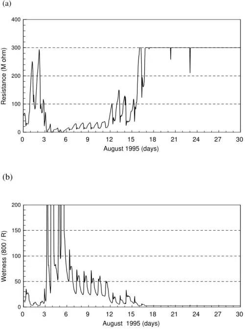
Saïd et al. (1999 and 2005) discusses moisture measurements results from long-term field monitoring applications of two heritage buildings. Figure 6 shows an example installation of moisture and temperature sensors in the wall of a heritage tower. Figure 7 shows an example of electric-resistance measurement from a ceramic moisture sensor and its presentation approach in terms of a wetness scale. The ceramic sensor (Figure 8) was mounted on the facade of a 4-story masonry building built in 1943 as a light industrial factory in eastern Canada. The structure consists of a concrete frame with solid brick masonry exterior walls 330 mm thick. The building was retrofitted and converted to offices in 1993-1994. The wall retrofit (Figure 9) included the addition of insulation and vapor and air barriers on the inside of the brick wall. A section of the retrofitted wall (Figure 9) was continuously monitored from April 1995 to June 1997. The main objectives of the long-term monitoring were to assess the impact of the retrofit on the
hygrothermal performance of the brick wall and to provide data for validation of hygrothermal models. Saïd et al. (2003) describes the monitoring program and discusses the impact of the retrofit strategy on the brick wall.
Graph b of Figure 7 demonstrates an approach to present electric-resistance measurements in terms of a wetness scale, which is calculated by the following equation:
R
Wetness
=
800
(4)Where R is the measured resistance in M , and the 800 is an arbitrary value.
The wetness scale is an arbitrary scale that illustrates changes in wetness conditions. Measurements in Figure 7 supported by the rainfall record, show that the noted month included a
Figure 6. Photograph of an example installation of moisture and temperature sensors on the wall of a heritage tower. Shown are: a pair of stainless-steel screws (MP) in a mortar joint, a stone moisture sensor (NS) and thermocouple (TC 51) installed at 200 mm depth in the wall, and a thermocouple (TC 54) glued to the facade. Notice the wire-cables are secured to the surface and a drainage U-loop is made in the cable to prevent water from running down into the moisture-pins. Saïd et al. (2005) describes the heritage tower and the monitoring program.
In this monitoring study (Saïd et al., 2003), results indicated that the retrofit strategy had a negligible effect on the drying potential of the brick wall during the summer months but reduced the wall drying potential during the winter months. The MC in the brick wall increased, which was partially due to the retrofit and partially due to a wetter weather during the monitoring period. As a result of increased MC, the thermal resistance (RSI) value of the 330 mm thick brick wall decreased from an average of 0.31 in the first winter months (Nov. 1995 to March 1996) following the retrofit to an average value of 0.18 in the second winter months (Nov. 1996 to March 1997). The brick wall may be at a higher risk of frost damage than before the retrofit as the number of freeze-thaw cycles has increased as result of the retrofit. The retrofit also increased the summer-to-winter mean temperature range of the brick wall by 16%, which might lead to higher thermal stresses in the wall depending on the degree of restraint by other structure members.
Figure 10 shows example output voltage measurements taken from two Sereda moisture sensors mounted on the facade of a 1953 circa 3-4 story laboratory building on the campus of the NRC in Ottawa, Canada. The exterior walls consisted of two layers of hollow clay tiles with a total width of approximately 400 mm. The outside finish of the wall was a white painted stucco. In 1993, to reduce heating and cooling loads and control air and moisture flow through the masonry walls, they were retrofitted with an exterior insulation finish system (EIFS) cladding. The finish of the new EIFS cladding system was also white stucco so that the building retained its
characteristic style. A section in each of the east and west facades was instrumented to monitor the long-term impact of the EIFS retrofit on the hygrothermal performance of the masonry wall and also to provide data for validation of computation models. Saïd et al. (1997) discusses the monitoring program and presents interim results of the thermal resistance of the retrofit wall and surface moisture. (a) 0 100 200 300 400 Resistance (M ohm) 0 3 6 9 12 15 18 21 24 27 30 August 1995 (days)
(b)
0 50 100 150 200 Wetness (800 / R) 0 3 6 9 12 15 18 21 24 27 30 August 1995 (days)Figure 7. Graphs of example electric-resistance measurements (graph a) from a ceramic moisture
Moisture-pins sensor
Printed circuit sensor
Figure 8. Photograph of the instrumentation on the facade including various moisture sensors (a
ceramic sensor, a Sereda sensor, a pair of stainless-steel screws moisture-pins, and a printed circuit) installed in the same location to compare their long-term performance. Notice the corroded condition of the printed circuit sensor after 2 years on the facade.
Figure 9. An elevation of monitored wall section showing retrofit assembly and locations of
some instrumentation. BCS = brick ceramic moisture sensor, HFLX = heat flux sensor, MP = moisture pin sensor, P = pressure transducer, PCCS = printed circuit condensation sensor, RH = relative humidity sensor, SS = Sereda moisture sensor, TC = thermocouple, and TP = platinum resistance temperature probe.
Wall assembly (from outside-to-inside): Original brick wall 330 mm thick, Tyvek,
Cavity space (260 mm deep at monitored section),
38x140 mm steel-stud framing, 394 mm on-centre,
140 mm mineral fibre insulation batt with paper-backed aluminum foil in the stud space (RSI 3.5), and 2 layers of 12.5 mm gypsum boards.
0 20 40 60 80 100
Sereda Sensor Output (mv)
0 1 2 3 4 5
September 1994 (days) 1/3-height wall-top
Figure 10. Graph of an example hourly averaged voltage measurements from two Sereda
moisture sensors indicating time-of-wetness and dryness of the facade due to diurnal
condensation (Figure 4 shows wiring diagram used in the measurements). In this graph, the time-line plot starts at midnight. Notice the variations in the output voltage (up to 86 mV) of the two sensors. The output of the sensor at one-third wall height shows 3-mV measurement noise when dry.
The results in Figure 10 indicate that exterior nighttime condensation is common during summer months when cool, clear nights occur after hot and humid days. In this figure, two Sereda moisture sensors mounted at different heights show TOW and dryness of the facade at the
sensors' locations. The Sereda sensors indicate the presence of wetness during the nighttime hours. Condensation occurs during the nighttime hours when exterior temperatures are lowest, RH is highest, and surface temperature drops below the dewpoint. For the results shown in Figure 10 the nighttime RH was 95% to 100%. Radiation to the night sky contributes to the cooling of the facade. The diurnal cycles shown in Figure 10 indicate that when the sun rises in the morning and heats up the facade, and the RH of the air falls, the wall rapidly dries out. Figure 10 also demonstrates the rapid response of the Sereda sensors to the changes in wetness conditions.
4. CONCLUSION
The article reviewed principles and performance of moisture measurements methods in building envelopes with a focus on continuous monitoring applications. Closely related literature has been compiled to facilitate accessibility by professionals. Also discussed is the author's experience in the application of some moisture sensors in the in situ monitoring of building envelopes. Brief example measurements were included to demonstrate measurement values and a presentation approach of measured electric-resistance data. The author's field experience
indicated that resistance- and voltage-based methods are most suitable for continuous monitoring applications as they can be readily connected to a data logging system. Voltage-based moisture sensors such as the Sereda and printed circuit sensors are usually used to indicate TOW of
REFERENCES
Altmann, K. 1974. Measurement of moisture in construction components made of EPS-concrete. In Proceedings of the 2nd International CIB/RILEM Symposium on Moisture Problems in
Buildings, Rotterdam, Netherlands, September 10-12, 1974; Paper No. 5.1.1., Springer,
Netherlands.
American Society for Testing and Materials Standards (ASTM). 1999. ASTM G84.729-89
Standard Practice for Measurement of Time-of-Wetness on Surfaces Exposed to Wetting Conditions as is in Atmospheric Corrosion Testing. West Conshohocken, PA: ASTM.
Assenheim, J. G. 1993. Moisture measurement in the concrete industry. Concrete Plant and
Production Journal, September/October, pp. 129-131.
Brandt, E. and Hansen, M. H. 1999. Measuring moisture content in wood with built in probes 20+ years of experience. In Proceedings of the 8th Durability of Building Materials and
Components Conference, Ottawa, Ontario, Canada: May 30-June 3, 1999; eds. M. Lacasse
and D. Vanver. National Research Council Canada, pp. 669-679.
Carll, C. and TenWolde, A. 1996. Accuracy of wood resistance sensors for measurement of humidity. Journal of Testing and Evaluation, ASTM 24(3) May, pp. 154-160.
Cunningham, M. J. 1985. Automatic data logging timber moisture contents over the range of 10% to 50% w/w. In Proceedings of 1985 Moisture and Humidity Symposium, Washington, DC, April 15-18, 1985; Instrument Society of America: Research Triangle Park, N.C., USA, pp. 475-483.
Dai, G. and Ahmet, K. 2001. Long-term monitoring of timber moisture content below the fiber saturation point using wood resistance sensors. Forest Products Journal 51 (5) May, pp. 52-58.
Dill, M. J. 2000. A review of testing for moisture in building elements. CIRIA Report No.
CIRIA-C538. London, UK: CIRIA.
Duff, J. E. 1966. A probe for accurate determination of moisture content of wood products in use.
Research Note FPL-0142, Aqugust. Madison, WI: Forest Products Laboratory, Forest
Service, US Department of Agriculture.
Forrer, J. B. and Vermaas, H. F. 1987. Development of an improved moisture meter for wood.
Forest Products Laboratory Journal 37(2), pp. 67-71.
Fugler, D. 1996. Straw bale moisture sensor study. Research and Development highlights. Canada Mortgage and Housing Corporation (CMHC), Ottawa, Ontario, Canada
Garrahan, P. 1988. Moisture meter correction factors. In Proceedings of a Seminar on In-Grade
Testing of Structural Lumber, Madison, WI, April 25-26, 1988. Madison, WI: Forest
Products Laboratory, Forest Service, US Department of Agriculture
Gayo, G., Palomo, A. and Macias, A. 1993a. Infrared thermography as a tool for studying the movement of water through some building materials - part 1: capillary moisture. European
Journal of Non-Destructive Testing, 2 (4) April, pp. 159-166.
Gayo, G., Palomo, A. and Macias, A. 1993b. Infrared thermography as a tool for studying the movement of water through some building materials - part 2: evaporation process. European
Journal of Non-Destructive Testing, 3(2) October, pp. 55-58.
Geary, P. J. 1970. Measurement of Moisture in Solids. A SIRA Institute, Kent, UK.
Gillespie, T. J. and Kidd, G. E. 1978. Sensing duration of leaf moisture resistance using electric impedance grids. Canadian Journal of Plant Sciences 58, pp. 179-187.
Gonzales, H. 1998. Homemade straw-bale-moisture meters. The last straw. International Journal
of Straw Bale and Natural Buildings 22, p. 31.
Goodhew, S., Griffiths, R. and Woolley, T. 2004. An investigation of moisture content in the walls of a straw-bale building. Building and Environment Journal 39, pp. 1443-1451. Hechler, J. J., Boulanger, J., Noël, D., Dufresne, R. and Pinon, C. 1990. A Study of Large Sets
of ASTM G84 Time-Of-Wetness Sensors. Corrosion Testing and Evaluation: Silver
Anniversary Volume, ASTM STP 1000, eds., R. Baboian and S.W. Dean. American Society
for Testing and Materials (ASTM), Philadelphia, PA, pp. 260-278.
Hedenblad, G. 1997. Measurement of moisture in high performance concrete. In Proceedings of
VTT Symposium 174 on Moisture Measurement in Concrete Constructions Exposed to Temperature and Moisture Variations. Espoo, Finland, August 22, 1997; eds., H. Kukko and
H. Paroll. Technical Research Centre of Finland (VTT), Espoo, Finland, pp. 105-119. Hedlin, C. P. 1965. A resistance-humidity relationship for sensors of the Dunmore type C.
Handbook on Humidity and Moisture. Measurement and Control in Science and Industry,
Vol. 1, ed. Wexler, A., Reinhold Publish Corp, New York, pp. 273-279.
Hutton, T. 1996. Monitoring Britain's heritage. Construction Repair, 10(1), January/February, pp. 41-42, 44.
James, W. L. 1975. Electric moisture meters for wood. In General Technical Report #FPL-6, U.S.
Department of Commerce, NTIS, AD-A014 540, Forest Products Laboratory, Forest Service,
US Department of Agriculture, Madison, WI.
James, W. L. 1994. Fundamentals of hand held moisture meters: an outline. In Proceedings of the
ASTM Hand-Held Moisture Meter Workshop, Forest Products Society, May 1993. Forest
Products Society, Forest Service, US Department of Agriculture, Madison, WI, pp. 13-16. Larsen, P. K. 2004. Moisture measurement in Tirsted Church. Journal of Architectural
Conservation 10 (1) March, pp. 22-35.
Norwegian Institute for Air Research (NILU). 1994. WETCORR in buildings. NILU Information
Rosina, E. and Spodek, J. 2003. Using infrared thermography to detect moisture in historic masonry: a case study in Indiana. APT Bulletin XXXIV (1), pp. 11-16.
Saïd, M. N. A., Brown, W. C. and Walker, I. S. 1997. Long-term field monitoring of an EIFS clad wall. Journal of Thermal Insulation and Building Envelopes 20 April, pp. 320-338.
Saïd, M. N. A., Brown, W. C., Shirtliffe, C. J. and Maurenbrecher, A. H. P. 1999. Monitoring of the building envelope of a heritage house - a case study. Energy and Buildings Journal 30 (3) , pp. 211-219.
Saïd, M. N. A., Demers, R. G. and McSheffrey, L. L. 2003. Hygrothermal performance of a masonry wall retrofitted with interior insulation. In Proceedings of the 2nd International
Conference on Building Physics, Antwerpen, Belgium, September 14-18, 2003; eds. J.
Carmeliet, H. Hens and G. Vermeir; A. A. Balkema Publishers, Exton, P.A., USA. pp. 445-454.
Saïd, M. N. A. 2004. Moisture measurement guide for building envelope applications. Institute
for Research in Construction, Research Report 190, August 20.
Saïd, M. N. A., Duchesne, D., Maurenbrecher, A. H. P., Ibrahim, K., Lumsdon, C., Stephenson, D. 2005. Monitoring the long-term performance of the Peace Tower in Ottawa. APT Bulletin 36 (1) May 1: pp. 53-59. Available at http://irc.nrc-cnrc.gc.ca/fulltext/nrcc47706/ (accessed July 17, 2007).
Scheurer, A. 1989. Moisture measurement systems and their application in concrete. Concrete
Precasting Plant and Technology 55 (3) March , pp. 90-92.
Sereda, P. J., Croll, S. G. and Slade, H. F. 1982. Measurement of the time of wetness by moisture sensors. Atmospheric Corrosion of Materials, American Society for Testing and Materials
Standards (ASTM) STP 767, pp. 267-285.
Voutilainen, J. 2005. Methods and instrumentation for measuring moisture in building structures. Helsinki University of Technology, Applied Electronic Laboratory Doctoral Thesis. Espoo, Finland. Series E: Electronic Publication E7, March 18, 2005: 157. Available at
http://lib.tkk.fi/Diss/2005/isbn9512275236/isbn9512275236.pdf (accessed July 17, 2007). Yamasaki, R. S., Slade, H. F. and Sereda, P. J. 1983. Determination of time-of-wetness due to
condensed moisture. Durability of Building Materials Journal. pp. 353-361.
Yamasaki, R. S. 1984. Characterization of wet and dry periods of plastic surfaces during outdoor exposure. Durability of Building Materials Journal 2 (2), pp. 155-169.
U.S. Forest Products Laboratory (FPL). Wood Engineering Handbook. 1982. Englewood Cliffs, NJ: Prentice-Hall, Inc.