Publisher’s version / Version de l'éditeur:
Fire Technology, 42, July 3, pp. 253-267, 2006-07-01
READ THESE TERMS AND CONDITIONS CAREFULLY BEFORE USING THIS WEBSITE. https://nrc-publications.canada.ca/eng/copyright
Vous avez des questions? Nous pouvons vous aider. Pour communiquer directement avec un auteur, consultez la
première page de la revue dans laquelle son article a été publié afin de trouver ses coordonnées. Si vous n’arrivez pas à les repérer, communiquez avec nous à [email protected].
Questions? Contact the NRC Publications Archive team at
[email protected]. If you wish to email the authors directly, please see the first page of the publication for their contact information.
NRC Publications Archive
Archives des publications du CNRC
This publication could be one of several versions: author’s original, accepted manuscript or the publisher’s version. / La version de cette publication peut être l’une des suivantes : la version prépublication de l’auteur, la version acceptée du manuscrit ou la version de l’éditeur.
For the publisher’s version, please access the DOI link below./ Pour consulter la version de l’éditeur, utilisez le lien DOI ci-dessous.
https://doi.org/10.1007/s10694-006-8431-7
Access and use of this website and the material on it are subject to the Terms and Conditions set forth at
Fire resistance furnace temperature measurements: plate
thermometers vs shielded thermocouples
Sultan, M. A.
https://publications-cnrc.canada.ca/fra/droits
L’accès à ce site Web et l’utilisation de son contenu sont assujettis aux conditions présentées dans le site LISEZ CES CONDITIONS ATTENTIVEMENT AVANT D’UTILISER CE SITE WEB.
NRC Publications Record / Notice d'Archives des publications de CNRC:
https://nrc-publications.canada.ca/eng/view/object/?id=8173bde1-154b-4421-a05d-7765113f78ce https://publications-cnrc.canada.ca/fra/voir/objet/?id=8173bde1-154b-4421-a05d-7765113f78ce
http://irc.nrc-cnrc.gc.ca
Fire resistance furnace temperature measurements: plate
thermometers vs shielded thermocouples
N R C C - 4 7 3 1 5
S u l t a n , M . A .
A version of this document is published in / Une version de ce
document se trouve dans: Fire Technology, v. 42, no. 3, July
2006, pp. 253-267 doi:
10.1007/s10694-006-8431-7
Fire Resistance Furnace Temperature Measurements: Plate Thermometers vs Shielded Thermocouples
Mohamed A. Sultan Fire Research Program Institute for Research in Construction National Research Council of Canada
Ottawa, Ontario, Canada K1A-0R6
ABSTRACT
This paper presents and discusses the results of fire resistance furnace temperature measurements using Plate Thermometers and shielded thermocouples as well as the heat exposure measurements to a test specimen in full-scale floor and wall furnaces. Comparisons of furnace temperature measured by the shielded thermocouples and by the Plate Thermometers, as well as heat exposure to a test specimen in floor and wall furnaces controlled by either the shielded thermocouples or by the Plate Thermometers, are presented.
INTRODUCTION
In North America, the fire resistance rating of building elements such as walls, floors, beams and columns is determined by a full-scale fire resistance test conducted in accordance to either the CAN/ULC-S1011or ASTM E1192 standards. These standards assume that different test furnaces will provide the same heat exposure to test specimens. Heat exposure in the fire resistance test furnaces depends on parameters such as the type of fuel used, furnace wall materials and furnace depth3. Different attempts were made to provide tools for harmonization of the heat exposure in standard fire resistance test furnaces. One attempt by the author3 suggests that if the full-scale fire resistance test furnaces are lined with very low thermal conductivity materials, such as ceramic fibre insulation, the heat exposure to a test specimen in different furnaces heated with either liquid or gaseous fuels or furnaces with different depths would be comparable. Other attempts were made at the Swedish National Testing Institute by
Wickstrom4,5,6 , by Olsson7 and at the Fire Research Station in UK by Cooke8 suggesting that in furnaces controlled with the so-called Plate Thermometers (PT), the heat exposure to a test specimen in the furnaces would be comparable. Wickstrom provided an interesting approach for determining the heat transfer by radiation and convection in fire resistance furnaces based on the furnace temperature measured by the plate thermometer and also suggested that the Gardon gauges heat flux meters may be used to measure the incident heat radiant flux in furnaces. Olsson presented a method of calibrating furnaces using the plate thermometers. Cooke conducted a study to compare the floor furnace temperature for 2 hours test using ISO conventional bare thermocouples to control the furnace and in the same time recorded the plate thermometers furnace temperature measurements as a non-controlling temperature was compared. He showed that the average temperature of the 4 plate thermometers is always lower than the average temperature of the 5 conventional bare thermocouples and explained that the difference is due to a slower time response of the plate thermometers but he provided no information on the time response of either of them. Wickstrom9 provided information on the theory and practical use of the PT. Currently, the ISO 834-110 and European EN 1363-111 standards require use of the PT to control the fire resistance test furnaces while the North American standards, CAN/ULC-S101 and ASTM E119, require use of the shielded thermocouples that are different than the bare conventional thermocouples9 to control fire resistance test furnaces. Babrauskas and Williamson12 provided detail analysis on the time response of thermocouples and showed that the errors associated with temperature measurement in fire resistance test furnaces are large in the first 20 minutes of test. The time constant is given by the following equation:
τ= ρ Cp V/h A
τ = time constant, ρ = density of bead, V = volume of bead, A = surface are of bead and h = heat transfer coefficient.
Harmonization of fire resistance test furnaces is a major challenge facing the standard writing organizations. Efforts are being considered by the ASTM E05 committee to investigate the factors that affect such harmonization among different laboratories’ test furnaces. The factors under consideration for furnace harmonization by ASTM include the furnace specifications, furnace control temperature measurement device and structural load. In an attempt to harmonize fire resistance test furnaces, three Task Groups have been formed by the ASTM E05.11 Subcommittee: one to investigate the effect of furnace specifications, the second, to investigate the potential use of the so-called Plate Thermometers for controlling a furnace temperature and the third to provide guidance on the load calculation and methodology of applying the load on a test specimen.
In contribution to these efforts, the National Research Council of Canada (NRC) conducted this experimental study to measure the furnace temperature as well as the heat exposure to a specimen in full-scale wall and floor furnaces controlled by either the shielded thermocouples or the Plate Thermometers. The ASTM E05 Committee may be interested to know what is the impact of changing the furnace measuring controlling device from the shielded thermocouples to plate thermometers on the existed and future fire resistance rating of building elements. Therefore, the objective of this paper is to provide data on the furnace-measuring devices for consideration by the North American fire resistance test standards committees.
Comparisons of a floor and a wall furnace temperature measured by both the shielded thermocouples, current North American standard, and by the Plate Thermometers for furnaces controlled by either the shielded thermocouples or by the Plate Thermometers are presented and discussed. Also, comparisons of heat exposure in floor and wall furnaces controlled by either the Plate Thermometers or by shielded thermocouples are also presented and discussed.
In addition, comparisons of heat exposure in floor and wall furnaces of different depths for furnaces controlled by either the Plate Thermometers or by the shielded thermocouples are presented and discussed.
EXPERIMENTAL WORK
Descriptions of the heat flux sensor, Plate Thermometer, shielded thermocouple, test specimens, full-scale wall and floor furnaces and experimental procedure are given below.
Heat Flux Sensor
Five heat flux sensors, water-cooled Gardon Gauges, were used to measure the heat exposure to a test specimen in the full-scale wall and floor furnaces. These gauges are of 25 mm diameter and 25 mm long copper cylinder and have a stated accuracy of ±3%. The cooling water flow temperature was maintained during the entire test within the temperature range specified by the manufacturer for the sensors.
Plate Thermometers
The Plate Thermometers used in this study were made by Thermo-Elecra and they are described in detail in Ref. 8, however, for the reader’s convenience, a brief description of the PT is given. The Plate Thermometer is a steel plate 100 mm by 100 mm by 0.7 mm thick with a surface emissivity greater than 0.7. On one side (back) facing the test specimen, a 1 mm Type K thermocouple is welded to the centre of the plate and covered with 10 mm thick ceramic fibreboard to protect it from radiative exchange with the specimen itself. The other side (front) of the steel plate is facing the furnace. The steel plate has a 15 mm diameter area around the centre and is specially treated to achieve a directional sensitivity to radiation. The Plate Thermometer is schematically shown in Figure 1. The Plate Thermometers were placed in both the floor and wall furnaces in locations similar to those shielded thermocouple locations required
by the North American fire resistance standards (see Figures 3 and 4) but at a distance of 100 mm away from the test specimen fire-exposed surface.
Shielded Thermocouples
The shielded thermocouple was fabricated by fusing the twisted ends of No. 18 gauge Chromel-Alumel wires, and mounting the leads inside a porcelain insulator. The thermocouple with the porcelain insulator was inserted inside a 12.7 mm diameter steel pipe so that the thermocouple bead was 12.7 mm away from a sealed end steel cap. The shielded thermocouple is schematically shown in Figure 2. The locations of these thermocouples are shown in Figures 3 and 4. These thermocouples are located 300 mm and 150 mm from the fire-exposed surface of the test specimen in floor and wall furnaces, respectively.
Test Specimens
In the floor furnace, the test specimen used was a castable refractory slab, marketed as KS-4, composed of 20 rectangular slabs, 800 mm wide by 1200 mm long by 1500 mm thick, suspended on a steel beam. The slabs were tightly butted with a ceramic sheet along their perimeters to form a 3.9 m by 4.8 m unit. For measuring the heat flux received by the test specimen, 5 heat flux sensors were installed flush with the specimen surface: one at the centre of the furnace and one at the centre of each quarter section of the furnace to measure the receiving heat exposure to the specimen surface as shown in Figure 3.
For the wall furnace, the test specimen composed of five so-called measuring specimens, slabs of KS-4 castable refractory brick, 600 mm square by 150 mm thick, were inserted in the simulated block brick wall covered with ceramic fire insulation on the fire-exposed side, one at its centre and four at the centres of its quarter sections as shown in Figure 4. As in the floor furnace mentioned-above for measuring the heat flux received by the test specimen,
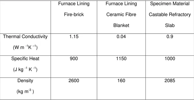
one heat flux sensor, water-cooled Gardon Gauge, was installed flush with the specimen surface in the centre of each measuring specimen. The location of these sensors is also shown in Figure 4. Each specimen was sealed at the edges against the furnace using ceramic fibre blankets. The properties of these slabs are given in Table 1.
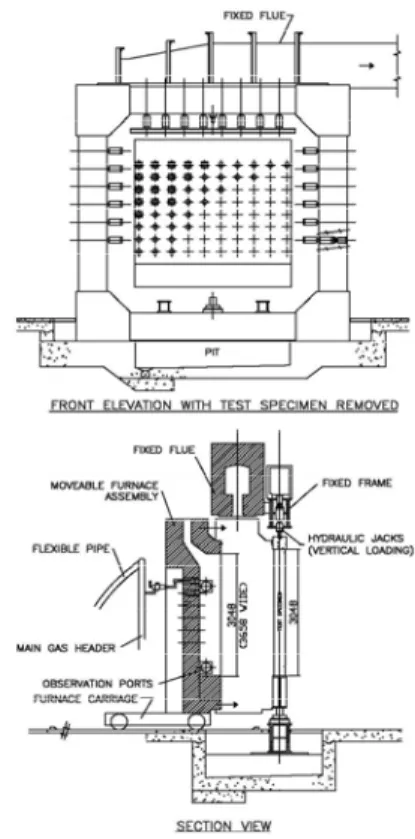
Full-scale Floor and Wall Furnaces
A full-scale fire resistance floor furnace is approximately 3.9 m wide by 4.8 m long by 3 m deep (see Figure 5) and the wall furnace is 3.6 m wide by 3 m high by 0.5 m deep (see Figure 6). In the floor furnace, the furnace walls were made of insulated firebrick while in the wall furnace, the furnace walls were covered with a ceramic fibre blanket. Thermal properties of the furnace wall are given in Table 1 above.
Experimental Procedure
The furnace temperature and heat exposure measurements for 12 experiments were carried out. The experiment duration was 2 hours and the data was recorded every 10 seconds. Six tests were conducted using a floor furnace: 3 duplicate tests with a furnace controlled by the shielded thermocouples in accordance to ULC-S101/ASTME119 standards and the other three duplicate tests by a furnace controlled with PT in accordance to ISO 834-1 and European EN 1363-1 standards. The other 6 tests were conducted using a wall furnace: 3 duplicate tests with a furnace controlled by the shielded thermocouples in accordance to ULC-S101/ASTME119 standards and the other three duplicate tests by a furnace controlled with PT in accordance to ISO 834-1 and European EN 1363-1 standards.
For furnaces controlled by the shielded thermocouples, the furnace temperature was measured by 9 (18 gauge) thermocouples in accordance with CAN/ULC-S101. The average of the 9 thermocouple temperatures was used to control the furnace temperature. For furnace
temperature controlled by the Plate Thermometers, the furnace temperature was measured by 5 thermometers and the average of these thermometer temperatures was used to control the furnace temperature. The wall and floor furnaces are controlled electronically in such a way that the furnace temperature follows as closely as possible, the CAN/ULC-S101 standard time-temperature curve. This curve is similar to the ASTM E1194 time temperature curve.
RESULTS AND DICUSSION
The effects of furnace temperature measurement methods and heat exposure to test specimens in fire resistance furnaces controlled by either the shielded thermocouples or by the Plate Thermometers are discussed below.
Furnace Temperature Control Methods
The main mechanisms of heat transfer in fire resistance test furnaces are by radiation and to a certain extent by convection. The radiation heat transfer depends on the furnace hot gases temperature and emissivity as well as on the conductivity and emissivity of furnace lining material. Very low thermal conductivity permits that the furnace lining wall temperature is closed to the hot gases temperature and this help the harmonization among different furnaces3
. The convective heat transfer depends on the furnace size. In larger furnace, convective heat occurs by natural convection, however, in small furnace, the convective heat could be by forced convection. It is important to use a temperature-measuring device that senses both mechanisms. The plate thermometer can measure the correct ratio of convective and radiative heat transfer for a flat surface, however, the conventional bare thermocouple does not satisfy correct ratio because the tip of the thermocouple is either spherical or hemispherical8. The shielded thermocouple may not also satisfy correct ratio because of the tip of the shield. The time constant of the temperature-measuring device of such shielded thermocouple affect the response only in the early stage in fire resistance test furnaces as report by Reference 12.
Furnace temperature measurements in a floor and a wall furnace controlled by either the shielded thermocouples or Plate Thermometers are given below.
Floor Furnace
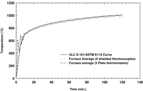
Comparisons of furnace average temperature measured by both the 9 shielded thermocouples and by 5 Plate Thermometers in a floor furnace controlled by either by the shielded thermocouples or the by Plate Thermometer, as well as the ULC S101/ASTM E119 standard time-temperature curve, are given in Figures 7 and 8.
In the furnace temperature measurements shown in Figure 7 for a floor furnace controlled by shielded thermocouples, the Plate Thermometer temperature measurements are much higher (up to 100%) in the first 8 min of the fire exposure than those measured by the shielded thermocouples. This could be due to a larger time constant (5 min to 7.2 min)2 for the shielded thermocouples specified by the North American fire resistance standards that fail to respond fast enough to a rapid change in the furnace temperature, however, the Plate Thermometers were able to respond faster due to a smaller time constant of 40 s8. After 8 min of fire exposure, the difference in furnace temperature measurements by the Plate Thermometers and by shielded thermocouples is insignificant. This could be explained that after 8 min, the furnace temperature increases at a slower rate so that, the effect of the difference in time constant for the Plate Thermometers and shielded thermocouples on the furnace temperature becomes insignificant. In Cooke study, the temperature of the plate thermometer as non-controlling furnace temperature was slightly lower than the conventional bare thermocouple and this was due to a larger response time of the plate thermometer compared to the conventional thermocouple. From the results of this study and Cooke’s study8, the time response of the furnace-measuring device plays a controlling role.
For a floor furnace temperature controlled by the Plate Thermometers (see Figure 8), the shielded thermocouples temperature measurements are much lower (up to 100%) in the first 8 min of fire exposure than those measured by the Plate Thermometers. This is due to a larger time constant for the shielded thermocouples than for Plate Thermometers. After 8 min, the shielded thermocouples temperature measurements are slightly lower (up to 5%) than those measured by the Plate Thermometers. As in the case when the floor furnace is controlled by the shielded thermocouples mentioned-above, the difference in furnace temperature measurements by the Plate Thermometers and by shielded thermocouples is also insignificant.
Wall Furnace
Figures 9 and 10 show comparisons of the average furnace temperature measured by both the 9 shielded thermocouples and by 5 Plate Thermometers in a wall furnace controlled by either the Plate Thermometer or by shielded thermocouples as well as the ULC S101/ASTM E119 time-temperature curve. The furnace temperature measurements shown in Figure 9 are more or less similar to those measured in the floor furnace mentioned-above. In a wall furnace controlled by shielded thermocouples, the Plate Thermometer temperature measurements are much higher (up to 100%) in the first 8 min of fire exposure than of those measured by the shielded thermocouples. This could be due to a larger time constant, as explained above, for the shielded thermocouples that fail to respond fast enough to the rapid change in the furnace temperature required by the standard, however, the Plate Thermometers were able to respond faster and measured higher temperatures than those measured by the shielded thermocouples. After 8 min of fire exposure, the difference in furnace temperature measurements is again insignificant. As explained above, in the case of the floor furnace where the furnace temperature increases at a slower rate, the effect of the difference in time constant for the Plate Thermometers and shielded thermocouples on the furnace temperature is insignificant.
For a wall furnace temperature controlled by the Plate Thermometers (see Figure 10), shielded thermocouples temperature measurements are much lower (up to 100%) in the first 8 min of fire exposure than those measured by the Plate Thermometers as in the case of the floor furnace mentioned-above. This is due to a larger time constant for the shielded thermocouples than for the Plate Thermometers. After 8 min, the shielded thermocouple temperature measurements are slightly higher (up to 5%) than those measured by the Plate Thermometers. As explained above, in the case of the floor furnace where the furnace temperature increases at a slower rate, the effect of the difference in time constant for the Plate Thermometers and shielded thermocouples on the furnace temperature measurements is insignificant.
Heat Exposure Measurements
Heat exposure measurements in a floor and a wall furnace with the furnace temperature controlled by either the shielded thermocouple or by Plate Thermometers are discussed below.
Floor Furnace
Figure 11 shows a comparison of the heat exposure received by a specimen in a floor furnace controlled by either the shielded thermocouples or by Plate Thermometers.
The results shown in Figure 11 indicate that when a floor furnace is controlled by shielded thermocouples, the specimen received about up to 100% more heat flux in the first 8 min than when the same furnace is controlled by Plate Thermometers. Similarly, after 8 min when the furnace is controlled by the shielded thermocouples, the specimen received approximately 12% more heat flux than when the furnace is controlled by Plate Thermometers. These results are consistent with the increase of the furnace temperature measured by the Plate
Thermometer rather than those measured by the shielded thermocouples for a floor furnace controlled by the shielded thermocouples.
Wall Furnace
A comparison of heat exposure received by a specimen in a wall furnace controlled by either the shielded thermocouples or by the Plate Thermometers is given in Figure 12.
The results shown in Figure 12 indicate that when a furnace is controlled by shielded thermocouples, the specimen received peaks of up to 100% more heat flux in the first 8 min than when the same furnace is controlled by the Plate Thermometers. After 8 min, when the furnace is controlled by the shielded thermocouples, the specimen received about 5% less heat flux than when the furnace is controlled by the Plate Thermometers.
Wall/Floor Furnaces controlled by Shielded Thermocouples
Figure 13 shows a comparison of the heat flux received by a specimen in a floor and a wall furnace controlled by shielded thermocouples. Results showed some oscillation in the heat flux for the first few minutes and this was due the difficulty of controlling the furnace temperature.
For a wall and a floor furnace controlled by shielded thermocouples, the results shown in Figure 13 indicate that in the first 8 min of fire exposure, the wall and floor furnace specimens received a significantly fluctuating heat flux due to the difficulty in controlling the furnace by the shielded thermocouples, with a longer time constant, that failed to respond fast enough to meet the rapid increase in furnace temperature required by the standard time-temperature curve. However, after 8 min, the heat flux received by either a floor or a wall specimen is more or less
the same. These results are consistent with the findings in temperature measurement shown in Figures 7 and 9.
Wall/Floor Furnaces controlled by Plate Thermometers
A comparison of the heat flux received by a specimen in a floor and a wall furnace controlled by the Plate Thermometers is given in Figure 14. Results showed some oscillation in the heat flux for the first few minutes and this was due the difficulty of controlling the furnace temperature.
For a wall or a floor furnace controlled by the Plate Thermocouples, the results shown in Figure 14 indicate that the heat flux received by a specimen in a wall furnace is about 15 % more than in a floor furnace specimen. As the two furnaces were controlled by the Plate Thermometers, this could be caused by one or more of the two following reasons: first, the furnace lining in the wall furnace was ceramic fibre blankets while in the floor furnace it was firebrick, so that the heat exposure to the specimen could be affected by the furnace walls material type. Second, the furnace depth: the floor furnace is 3 m deep and the wall furnace is 0.5 m deep so that the furnace depth could affect the heat exposure to the specimen. Further research is needed to investigate the effect of furnace depth and furnace lining material on heat flux received by a specimen in floor and wall furnaces.
Summary of Results
This paper discusses two methods for controlling the furnace temperature in a floor and a wall fire resistance furnace. It also discusses the incident heat flux received by a specimen in a floor and wall furnace controlled by either shielded thermocouples or by the Plate Thermometers. Based on the results mentioned above, the following key trends can be highlighted:
1. For the initial fire exposure (8 min) in either a floor or a wall furnace controlled by either the shielded thermocouples or by the Plate Thermometers, the difference between furnace temperatures measured by shielded thermocouples and by the Plate Thermometer is significant and this may affect shorter duration tests. However, after 8 min, in longer duration tests, the difference is insignificant.
2. In the initial fire exposure (8 min) in either a floor or a wall furnace controlled by the shielded thermocouples, the specimen received peaks of up to 100% more heat flux than when the same furnace is controlled by the Plate Thermometers. However, after 8 min, the floor and wall furnace specimen received 12% and 5%, respectively, more heat flux than when the same furnace is controlled by the Plate Thermometers.
3. For wall and floor furnaces controlled by the shielded thermocouples, the specimen in the wall furnace receives a similar heat flux as for the specimen in the floor furnace.
4. In wall and floor furnaces controlled by Plate Thermometers, the specimen in the wall furnace received about 15% more heat flux than the specimen in the floor furnace.
5. Further research is needed to investigate the effect of furnace lining materials and furnace depth on heat exposure to test specimen and temperature measuring device in fire resistance test furnaces. Also, to measure temperatures within well define specimens tested in different furnaces controlled by either the plate thermometers or by shielded thermocouples.
ACKNOWLEDGEMENTS
The author wishes to thank Jocelyn Henrie, Yves Seguin, Roch Monette and Patrice Leroux for their help in conducting the experimental work.
REFERENCES
1. CAN/ULS-S101-M89, “Standard Methods of Fire Endurance Tests of Building Construction and Materials”, ULC, Scarborough, Ontario, Canada, 1989.
2. ASTM E119-88, “Standard Methods of Fire Tests of Building Constructions and Materials”, ASTM, Philadelphia, PA, 1995.
3. Sultan, M. A. and Denham, M. “Harmonization of the Fire Severity in Standard Fire Resistance Test Furnaces”, Fire Safety Sciences – proceedings of the Fifth International Symposium, 1997.
4. Wickstrom, U., “Fire Technology, Vol. 30, No. 2, PP 195, 1994.
5. Wickstrom, U., “Proposal Regarding Temperature Measurements in Fire Resistance Furnaces”, SP-Report 1986: 17, Swedish National Testing and Research Institute, 1986. 6. Wickstrom, U., ”The Plate Thermometer – A simple Instrument for Reaching Harmonized
Fire Resistance Tests”, SP- Report 1989:03, Swedish National Testing and Research Institute, 1989.
7. Olsson, S., “Calibration of Fire Resistance Furnaces with Plate Thermometers”, BCR – report, EUR No. 14555 EN, Commission of European Communities, 1993.
8. Wickstrom, U., ”The Plate Thermometer – Practical Aspects”, SP- Report 1997:28, Swedish National Testing and Research Institute, 1997.
9. Cooke, Gordon, “Can Harmonization of Fire Resistance Furnaces be Achieved by Plate Thermometer control?”, Fire Safety Science-Proceedings of the Fourth International Symposium, 1994.
10. ISO 834-1, “Fire Resistance Tests Elements of Building Construction – Part 1: General Requirements”, International Organization for Standardization, CH – 1211 Geneva 20, Switzerland, 1999.
11. The European Standard EN 1363-1:1999, “Fire Resistance Tests – Part 1: General Requirements”, European Committee for Standardization, rue de Stassart 36, B-1050 Brussels, 1999.
12. Babrauskas, V and Williamson, R. B., “Temperature Measurement in Fire Test Furnaces”, Fire Technology, 14, 1978.
Table 1 Thermal Property of Furnace Lining and Specimen Materials Furnace Lining Fire-brick Furnace Lining Ceramic Fibre Blanket Specimen Material Castable Refractory Slab Thermal Conductivity (W m -1K –1) 1.15 0.04 0.9 Specific Heat (J kg -1 K -1) 900 1150 1000 Density (kg m-3 ) 2600 160 2085
Time (min.) 0 20 40 60 80 100 120 140 Temper atur e ( °C ) 0 200 400 600 800 1000 1200
ULC S-101/ASTM E119 Curve
Furnace average ( 9 shielded thermocouples) Furnace average (5 Plate thermometers)
Figure 7 Comparison of Floor Furnace Temperature (Furnace Controlled by the Shielded Thermocouples)
Time (min.) 0 20 40 60 80 100 120 140 Te m per a tur e (°C ) 0 200 400 600 800 1000 1200
ULC S-101/ASTM E119 Curve
Furnace average ( 9 shielded thermocouples) Furnace average (5 Plate thermometers)
Figure 8 Comparison of Floor Furnace Temperature (Furnace Controlled by the Plate Thermometers)
Time (min.) 0 20 40 60 80 100 120 140 Temp er atu re ( °C) 0 200 400 600 800 1000 1200
ULC S-101/ASTM E119 Curve
Furnace Average (9 shielded thermocouples) Furnace average (5 Plate thermometers)
Figure 9 Comparison of Wall Furnace Temperature (Furnace Controlled by the Shielded Thermocouples)
Time (min.) 0 20 40 60 80 100 120 140 Te m pe ratur e ( °C ) 0 200 400 600 800 1000 1200
ULC S-101/ASTM E119 Curve
Furnace Average (9 shielded thermocouples) Furnace average (5 Plate thermometers)
Figure 10 Comparison of Wall Furnace Temperature (Furnace Controlled by the Plate Thermometers)
Time (min.) 0 20 40 60 80 100 120 140 H e at Fl ux ( k W /m 2) 0 20 40 60 80 100 120 140 160
Average Heat Flux (Controlled by Shielded Thermocouples) Average Heat Flux (Controlled by Plate Thermometers)
Figure 11 Comparison of Heat Exposure in Floor Furnace
Time (min.) 0 20 40 60 80 100 120 140 Heat Flux (kW/m 2) 0 20 40 60 80 100 120 140 160 180
Average Heat Flux (Controlled by Shielded Thermocouples) Average Heat Flux (Controlled by Plate Thermometers)
Time (min.) 0 20 40 60 80 100 120 14 0 20 40 60 80 100 120 140 160 180 0 2) F lux (kW/m Heat
Average Heat Flux (Floor Furnace) Average Heat Flux (Wall Furnace)
Figure 13 Comparison of Heat Exposure
(Furnace Controlled by Shielded Thermocouples)
Time (min.) 0 20 40 60 80 100 120 140 H e a t Fl ux ( k W /m 2) 0 20 40 60 80 100 120 140 160 180
Average Heat Flux (Floor Furnace) Average Heat Flux (Wall Furnace)
Figure 14 Comparison of Heat Exposure (Furnace Controlled by Plate Thermometers)