Publisher’s version / Version de l'éditeur:
Polymer Engineering and Science, 45, 6, pp. 827-837, 2005-04-15
READ THESE TERMS AND CONDITIONS CAREFULLY BEFORE USING THIS WEBSITE. https://nrc-publications.canada.ca/eng/copyright
Vous avez des questions? Nous pouvons vous aider. Pour communiquer directement avec un auteur, consultez la première page de la revue dans laquelle son article a été publié afin de trouver ses coordonnées. Si vous n’arrivez pas à les repérer, communiquez avec nous à [email protected].
Questions? Contact the NRC Publications Archive team at
[email protected]. If you wish to email the authors directly, please see the first page of the publication for their contact information.
NRC Publications Archive
Archives des publications du CNRC
This publication could be one of several versions: author’s original, accepted manuscript or the publisher’s version. / La version de cette publication peut être l’une des suivantes : la version prépublication de l’auteur, la version acceptée du manuscrit ou la version de l’éditeur.
For the publisher’s version, please access the DOI link below./ Pour consulter la version de l’éditeur, utilisez le lien DOI ci-dessous.
https://doi.org/10.1002/pen.20336
Access and use of this website and the material on it are subject to the Terms and Conditions set forth at
Melt compounding of different grades of polystyrene with organoclay :
Part 3 : Mechanical properties
Tanoue, Shuichi; Utracki, Leszek A.; Garcia-Rejon, Andres; Tatibouët,
Jacques; Kamal, Musa R.
https://publications-cnrc.canada.ca/fra/droits
L’accès à ce site Web et l’utilisation de son contenu sont assujettis aux conditions présentées dans le site LISEZ CES CONDITIONS ATTENTIVEMENT AVANT D’UTILISER CE SITE WEB.
NRC Publications Record / Notice d'Archives des publications de CNRC:
https://nrc-publications.canada.ca/eng/view/object/?id=002335e2-91bc-4b83-a556-c42dcf915856 https://publications-cnrc.canada.ca/fra/voir/objet/?id=002335e2-91bc-4b83-a556-c42dcf915856Melt Compounding of Different Grades Polystyrene With
Organoclay. Part 3: Mechanical Properties
Shuichi Tanoue
Department of Materials Science and Engineering, University of Fukui, 3-9-1 Bunkyo, Fukui 910-8507, Japan
Leszek A. Utracki, Andres Garcia-Rejon, Jacques Tatiboue¨t
Industrial Materials Institute, National Research Council Canada, 75 de Mortagne Blvd., Boucherville, Quebec J4B 6Y4, Canada
Musa R. Kamal
Department of Chemical Engineering, McGill University, 3610 University Street, Montreal, Quebec H3A 2B2, Canada
We discuss the effects of the melt compounding vari-ables, matrix molecular weight and organoclay content on the X-ray diffraction (XRD) and mechanical properties of polystyrene (PS)/organoclay nanocomposites (PNC) prepared in a twin-screw extruder. An increase of resi-dence time reduced the height of the first XRD peak and increased that of the second peak. Barrel temperature and screw configuration had a little influence on the tensile properties and impact strength. Young’s modu-lus increased with organoclay content and it was almost independent of matrix PS molecular weight. The stress-at-break and impact strength decreased with organo-clay content and increased with PS molecular weight. Young’s modulus and impact strength decreased with residence time. Since the slopes of these dependencies for PNC were similar to that of the neat PS, the matrix degradation seems to play the major role. The relation-ship between impact strength and elongation at break of PNC showed high dependency on matrix grade. How-ever, better empirical correlation was observed between the impact and tensile strengths. According to theoret-ical model of Ji et al. [32], the Young’s modulus vs. clay concentration dependence indicated the presence of low interphase thickness. POLYM. ENG. SCI., 45:827– 837, 2005. © 2005 Society of Plastics Engineers
INTRODUCTION
One of the advantages of adding organoclay to a polymer matrix, i.e., making a polymer nanocomposite (PNC), is the
improvement of mechanical properties. For example, incor-poration of 4.2 wt% of exfoliated montmorillonite into polyamide-6 (PA-6) increases the Young’s modulus by a factor of 2.1 [1]. More recently, mechanical properties of PNC with polypropylene (PP) [2– 4], polyamide-66 (PA-66) [5], polystyrene (PS) [6 – 8], etc., have been studied. Exper-imentally, when exfoliation is achieved, the Young’s mod-ulus of PNC with 4 wt% clay increases by a factor of approximately 1.5 to 2 over that of the neat matrix polymer [9]. However, such mechanical properties as tensile strength, elongation at break, or impact strength generally decrease with clay content. Of note, the modulus is calcu-lated at the vanishingly low strains, whereas the other prop-erties are determined at strains that correspond to yield or break, at which the stress transfer between matrix and reinforcing particles is important.
The early methods for the production of PNC were based on in-situ polymerization, i.e., an organoclay was dispersed in a monomer, which subsequently was polymerized. Cur-rent research focuses on the melt compounding process. For example, organoclay may be dispersed in a PA-6 matrix using either a twin-screw (TSE) or single-screw extruder (SSE) [10, 11]. Owing to the polar nature of PA-6, clay exfoliation, by melt compounding with suitable organoclay, is relatively easy. For example, a suitable organoclay for PA is Cloisite威 30B (montmorillonite [MMT] intercalated with methyl tallow di-2-hydroxy ethyl ammonium chloride) or SCPX-2004 (MMT with methyl rapeseed di-2-hydroxyl-ethyl ammonium chloride). However, in the case of less polar polymers, melt compounding is difficult, requiring good thermal stability and often compatibilization. Thus, it is important to find the optimum conditions for PNC prep-aration by melt compounding.
Self-diffusion of polymer chains in the molten state is
Correspondence to: S. Tanoue; e-mail: [email protected] Andres Garcia-Rejon is deceased; he died in March 2002.
Contract grant sponsor: Natural Sciences and Engineering Research Coun-cil (Canada).
DOI 10.1002/pen.20336
Published online in Wiley InterScience (www.interscience.wiley.com). ©2005 Society of Plastics Engineers
low, viz. the self-diffusion coefficient: Ds⫽ 10 –10
to 10–16 m2/s, i.e., 1 min diffusion time results in the displacement ranging from 25 to 0.025 m, respectively [12]. Therefore, mechanical mixing is required for the effective preparation of PNC. TSE is the most common compounding system for this purpose. Considering the dynamics of twin screw ex-trusion, variables such as barrel temperature, screw speed, feed rate, and screw configuration are expected to affect the properties of the resulting PNC.
In the aforementioned studies [10, 11], the PNCs were prepared by compounding the resin with organoclay nano-composites in a TSE or SSE, the former producing material with better performance characteristics. The authors ob-served that it was imperative to provide adequate residence time in the extruder and appropriate shear history. The degree of dispersion in the TSE correlated well with the mean residence time and dimensionless variance (which indicates residence time distribution), but not with the type of the machine or the stress field. Since the experiments were carried out at constant throughput, the results imply that strain is important for the preparation of PNC in a TSE. More recently, PA-6 based PNC were prepared in a TSE using water slurry of Na-MMT [13]. The properties of the product were nearly equal to those of conventional PNC.
Melt compounding has been successfully carried out using hydrophilic polymers as the matrix, viz. polyvinyl pyrrolidone, polyethylene glycol, and polyvinyl alcohol. There are some experimental studies suggesting the feasi-bility of the preparation of PNC from such polymers by melt compounding under selected process conditions, e.g., PP [14], poly[ethylene-co-(vinyl acetate)] (EVA) [15], PA-6 [13, 16], etc. However, systematic studies of melt com-pounding of PNC are scarce. A high degree of exfoliation was obtained by dispersing up to 9 wt% of Cloisite威 30B in a semiaromatic copolyamide [17] in a small TSE. Good results were also obtained using polycarbonate [18, 19] or epoxy [20]. Generally, it is quite difficult to exfoliate clay in low-polarity polymers, such as polystyrene [21, 22] or poly-olefins [23].
The aim of this study was to provide a guideline for melt compounding of PS-based nanocomposites. In this article, we present the method used to melt-compound the PS-based PNC in a co-rotating TSE. Then, the effects of various processing conditions on the tensile and impact properties are presented, focusing on the interrelation between the extrusion conditions and mechanical properties. Cloisite威 10A and three grades of PS (with different molecular weight, Mw) were used. The effects of Mw of PS on
me-chanical properties of PNC are also discussed.
EXPERIMENTAL
Materials
Three PS grades were used. These are coded as LMW, MMW, and HMW, for low (Mw ⫽ 230 kg/mol), medium
(Mw⫽ 270 kg/mol), and high (Mw ⫽ 310 kg/mol) weight
average molecular weight respectively [21, 22]. The or-ganoclay (Cloisite威 10A) is a MMT (cation exchange ca-pacity [CEC] ⫽ 0.926 meq/g, d001⫽ 1.17 nm) intercalated
with 1.25 meq/g of di-methyl benzyl hydrogenated tallow ammonium chloride (2MBHTA), which increased the inter-layer spacing to d001⫽ 1.92 nm.
Melt Compounding
As described in Part 1 of this series of articles [21], a Leistritz co-rotating twin-screw extruder TSE-34 (screw length/diameter ratio (L/D) ⫽ 40) was used. The residence time and its distribution inside the TSE were measured using an ultrasonic probe. The special die for in-line ultrasonic (US) monitoring was placed at the extruder exit. Detailed informa-tion regarding the equipment and procedures used in these measurements may be found elsewhere [24, 25].
In this study, the effects of: 1) PS grade; 2) organoclay content; 3) residence time; 4) barrel temperature (TB); and
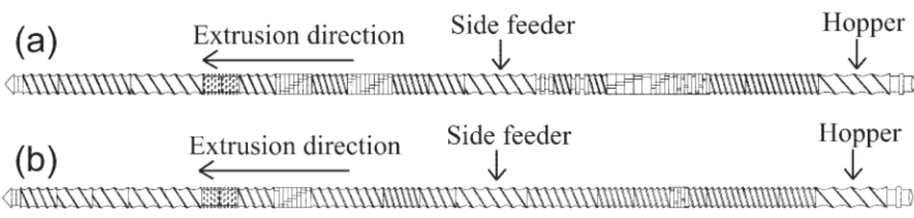
5) screw configuration on PNC’s performance were exam-ined (see Table 1). In Table 1, “Double pass” means that the PNC was first extruded by feeding PS from the hopper and the organoclay from the side feeder, and then the extrudates were loaded into hopper and reextruded under the same conditions as for the first pass (screw rotation, feed rate, barrel temperature, and screw configuration). Since PS is amorphous, the degree of clay dispersion is not affected by vitrification. Thus, the PNC may be remelted. Accordingly, “double pass” is equivalent to extrusion with a long resi-dence time, calculated as the sum of resiresi-dence times of organoclay during the first and second passes through TSE. Normally, during the first (or single) pass, the organoclay was added from a side feeder. To test the influence of the feed mode, LS-2-5 specimen was extruded using a dry-blend of PS pellets and organoclay powder. As illustrated in Fig. 1, two types of screws were used, the high shear (HS) and low shear (LS) screws. The former screw had 30% and the latter screw 10% kneading and mixing elements. X-ray Diffraction
X-ray diffraction (XRD) measurements were carried out using a Rigaku Rotaflex X-ray diffractometer with Cu-rotating anode and 2 scan. XRD scans were obtained using an incident X-ray wavelength of ⫽ 0.15406 nm at a scan rate of d/dt ⫽ 1.5°/min. X-ray analysis was performed on the specimens prepared by compression molding at 200°C [21].
Mechanical Testing
Extruded PNC pellets were injection molded using a BOY-30A machine into standard tensile specimens (ASTM D638, Type I) and bars for Izod impact tests (ASTM D256). The barrel temperature was 200°C, mold temperature of 40°C, injection pressure of 18 MPa, a holding pressure of 7 MPa, and a cooling time of 20 s.
Tensile tests were carried out according to ASTM D638 using an Instron 5500R model 1125 tester. Crosshead speed was set up at 5 mm/min. An extensometer was used to accurately measure the strain. Young’s modulus was calcu-lated by least square formfitting of the experimental data of stress vs. strain in the initial region of strain from 0 to 0.2%. Notched Izod impact tests (procedure ASTM D256) were performed at room temperature using an Instron Model 8200 impact tester. Property values reported here represent an average of 10 tests for each specimen. Before the tensile or impact tests, the specimens were dried under vacuum at 60°C for at least 48 h.
RESULTS
Residence Time Distribution
The residence time distribution was measured at screw rotation speed of N ⫽ 200 rpm, TB⫽ 200°C by means of an
ultrasonic probe at frequency ⫽ 5 MHz. CaCO3was used
as the ultrasonic tracer. As shown in Part 1 [21], the
resi-dence time distribution curves for the three PS grades were quite similar—the peak position moved very slightly to shorter times as the Mw of PS increased. Otherwise, the
curves virtually superimposed. Since the test results were insensitive to the melt flow properties, these measurements were carried out using neat MMW PS. The residence time distribution vs. feed rate was determined (see Fig. 2 and Table 1). The data can be approximated by a simple hyper-bolic relation of the main feed rate, Q:
t⫽ a0⫹ a1/Q. (1)
The effect of residence time, t ⫽ 62.7 to 406 s, on the degree of clay dispersion (as evidenced by the XRD scans) is displayed in Fig. 3, while that on the mechanical behavior is presented in Fig. 4.
TSE Barrel Temperature and Screw Configuration The effect of the screw configuration and the barrel temperature on the degree of dispersion, as indicated by TABLE 1. PS/organoclay mixtures prepared by melt compounding.*
Sample code Screw TB(°C) a Q(PS)b (kg/h) Q(C10A)c (kg/h) Double pass
Mean residence timed
t(s), single/double HS-0-5 HS 180 or 200 5 0 Yes – HS-1-5 HS 200 5 0.05 169/– HS-2-5 HS 180 or 200 5 0.1 Yes 169/406 HS-5-5 HS 180 or 200 5 0.25 Yes 169/406 HS-10-5 HS 200 5 0.5 169/– HS-0-10 HS 200 10 0 Yes – HS-2-10 HS 200 10 0.2 Yes 96.1/229 HS-5-10 HS 200 10 0.5 Yes 96.1/229 HS-0-20 HS 200 20 0 Yes – HS-2-20 HS 200 20 0.4 Yes 62.7/148 HS-5-20 HS 200 20 1.0 Yes 62.7/148 LS-0-5 LS 180 or 200 5 0 – LS-2-5 LS 180 or 200 5 0.1 Not measured LS-5-5 LS 180 or 200 5 0.25 Not measured
*Common conditions: Screw rotation speed was N ⫽ 200 rpm. Double pass was done at barrel temperature of 200°C.
aT
Bis barrel temperature.
bQ(PS) is PS feed rate in the hopper. cQ(C10A) is feed rate of Cloisite
威 10A using side feeder.
dOrganoclay residence time as measured by ultrasonic.
FIG. 1. TSE screw design and the location of side feeder. a: High shear type screw (HS). b: Low shear type screw (LS).
XRD, is illustrated in Fig. 5. Note the similarity between scans for LS-180°C, LS-200°C and HS-180°C.
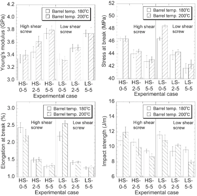
Figure 6 displays the tensile properties and impact strength for the PNC specimens containing 0, 2, or 5 wt% organoclay, compounded at constant feed rate of Q ⫽ 5 kg/h at TB⫽ 180 or 200°C using either LS or HS screw
config-uration (see Table 1). There is large experimental variability in these measurements. Thus, only the global tendency is important.
PS grade and organoclay content
The influence of PS grade and organoclay content on the mechanical properties is illustrated in Fig. 7 (for XRD-curves, see Part 1 [21]). By contrast with other properties, the Young’s modulus is almost independent of molecular weight of the PS. Its dependence on organoclay content can be approximated (correlation coefficient r ⫽ 0.988) by a linear equation:
Ec⫽ 3.4 ⫹ 0.0631w (2)
where Ec is Young’s modulus of composite and w is
or-ganoclay content.
DISCUSSION
Effect of Residence Time
Figure 2 displays the distribution of residence time at TB
⫽ 200°C and N ⫽ 200 rpm for three feed rates at the TSE hopper. As indicated, Fig. 2a displays the distribution curves for tracer added from the side feeder, whereas Fig. 2b for tracer added from the hopper. These experimental data may be char-acterized by two parameters: the mean residence time, t, and its normalized variance, 2. Their numerical values were com-puted using the follow equations:
t⫽
冕
0 ⬁ tE共t兲 dt (3) 2 ⫽t 2 t2 ⫽冕
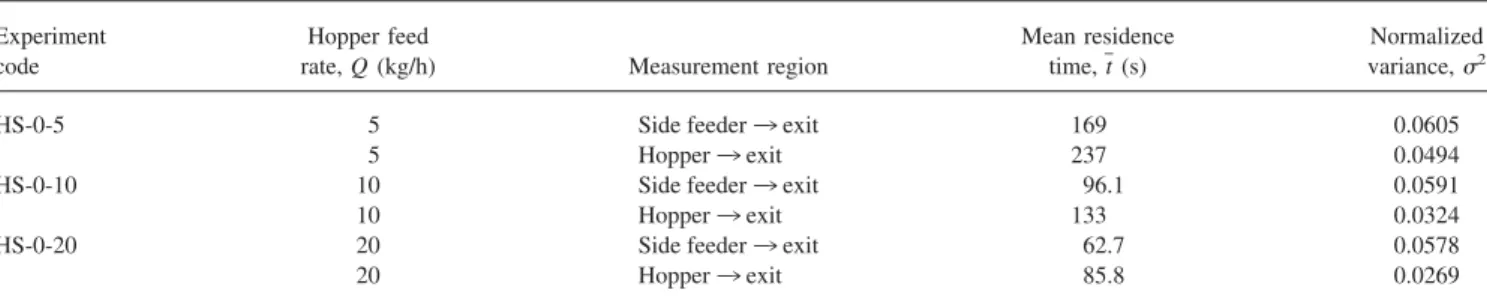
0 ⬁ 共t ⫺ t兲2E共t兲 dt t2 (4)where E(t) is the residence time distribution. The computed values are listed in Table 2. Evidently, t and 2 decrease with the feed rate, Q. Noteworthy, the distribution curves are sharper for the tracer flow from the hopper to the exit (die) than those for feeding the tracer from the side feeder. Both these parameters, t and 2follow the hyperbolic Eq. 1, with the parameters listed in Table 3.
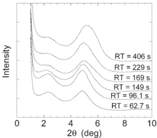
As shown in Table 2, at the slowest feed rate, Q ⫽ 5 kg/h, the residence time t ⫽ 169 or 237 s depends on whether the tracer flow is from the side feeder or from the FIG. 3. X-ray diffraction results for MMW PS with 5 wt% organoclay extruded using high-shear screw at 200°C (5, 10, and HS-5-20). The residence time varied from (bottom) 62.7 to 406 s (top).
FIG. 2. Residence time distribution in a TSE with high shear type screw at three feed rates. Screw rotation speed was N ⫽ 200 rpm and barrel temperature 200°C.
main hopper, respectively. For the “double pass” extrusions, the residence time was calculated as the sum of the resi-dence time from side feeder to exit (first extrusion) plus that from hopper to exit of the TSE (second extrusion). The minimum and maximum residence times in this study were t ⫽62.7 and 406 s, respectively.
The changes in XRD spectra caused by shearing PNC in the TSE within the full range of residence time are indicated in Fig. 3. For these tests, PS was compounded with 5 wt% organoclay at TB
⫽ 200°C and N ⫽ 200 rpm. There are two peaks on each XRD curves. The first is located at 2 ⬇ 2.2 to 2.3° and the second at 2 ⬇ 4.8 to 5.3°. The interlayer spacing calculated from Bragg’s formula is d001⬇ 3.8 to 4.0 and 1.7 to 1.8 nm, respectively [21].
Thus, the first peak indicates intercalation of Cloisite威 10A by PS macromolecules expanding the galleries (from the original value of d001⫽ 1.92 nm), while the second indicates the opposite effect.
The first peak decreased in intensity with increasing residence time, while the second peak increased and its position also moved slightly to higher scattering angles, indicating progressive reduc-tion of the interlamellar gallery heights. The origin of such a reduction was traced by Fourier Transform Infrared Spectroscopy (FTIR) spectra to the thermomechanical degradation of the inter-calant [21].
Dennis et al. [10] demonstrated that it is not the intensity of the stress field in the TSE, but the residence time that is responsible for intercalation, as the intercalation and/or
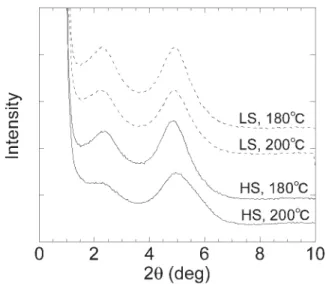
ex-FIG. 5. X-ray diffraction results for PS/organoclay nanocomposites at TB
⫽ 180 and 200°C, for high-shear (HS) and low-shear (LS) screws. FIG. 4. Mechanical performance of MMW PS with 0, 2, and 5 wt% organoclay as a function of the residence
foliation requires time. However, for the thermally unstable PS/Cloisite威 10A systems, the long residence time increases the effects of thermal degradation and causes reduction of spacing between the clay platelets, and thus reaggregation. The two processes, the time dependent intercalation and degradation, occur simultaneously. Detailed analysis of data indicates a local maximum of dispersion for residence time t ⬇ 100 s, and worsening dispersion at longer residence times. Yoon et al. [19] reported similar behavior for the polycarbonate-based PNC.
Figure 4 displays the mechanical properties (Young’s modulus, stress at break, elongation at break and impact strength) as functions of residence time for the nominal organoclay loadings of 0, 2, and 5 wt%. For PNC, the Young’s modulus seems to reach a local maximum at res-idence time t ⬇ 100 s, then it decreases. Stress and
elon-gation at break also decrease with residence time, reaching a plateau at long shearing times.
For all three compositions, the impact strength decreased with increase of residence time. The linear curve fitting of Young’s modulus and impact strength data gave almost the same slope for all three compositions. Thus, deterioration of the PS matrix seems to be the main culprit for the reduced performance at longer residence times. The thermooxidative degradation of PS seems to be responsible for the loss of performance [21, 22].
Effect of Barrel Temperature and Screw Configuration To study the effect of barrel temperature, TB, and screw configuration on the organoclay dispersion and perfor-mance, MMW PS with 5 wt% organoclay was compounded FIG. 6. Tensile properties and impact strength for PNC compounded in a TSE under the conditions listed in
in a TSE at a screw rotation speed of N ⫽ 200 rpm and feed rate of Q ⫽ 5 kg/h, at TB⫽ 180 or 200°C. The two screw
configurations presented in Fig. 1, HS and LS, were used. Figure 5 displays the XRD spectra for the resulting speci-mens.
As in the case of Fig. 3, all the curves in Fig. 5 are characterized by the presence of two peaks. The first peak corresponds to short organoclay stacks with expanded in-terlayer spacings to about d001 ⬇ 4 nm, while the second
corresponds to clay stacks with reduced interlayer spacing, viz. d001 ⬇ 1.7 nm. The relative population of these two
clay types can be judged by the height of the corresponding peak. The first peak of the specimen extruded at TB
⫽ 200°C using the HS screw is very small and the peak position of this specimen is located at the highest 2 ob-served for the four cases. The three other spectra are similar, indicating an equivalence between the LS screw at TB
⫽ 180 and 200°C and HS screw at TB⫽ 180°C. The first
peak position of the specimen extruded using the LS screw configuration is lower than for those extruded using the HS screw. Therefore, judging by the XRD data alone, the best dispersion of Cloisite威 10A in the PS matrix is obtained under the mildest compounding conditions using low shear
FIG. 7. Tensile and impact strength properties as a function of organoclay contents for three grades of PS.
FIG. 8. Izod impact strength vs. elongation at break for various PS based organoclay nanocomposites. Barrel temperature of 200°C, screw rotation speed of 200 rpm, feed rate of 5 kg/h, and organoclay contents of from 0 to 10 wt%.
(LS) screw configuration. These conditions seem to provide optimal balance between degradation and dispersion, under the conditions included in this study.
According to Fig. 6, the Young’s modulus for specimens compounded using HS screws at TB⫽ 200°C is
systemat-ically higher than for those prepared at 180°C—this ten-dency is absent for the LS screw configuration. Since the trend is the same for the neat resin, evidently the tempera-ture effect is unrelated to the degree of clay dispersion. Comparison between the LS and HS specimens indicates that marginally higher moduli (within the range of experi-mental error) are observed for the latter screw configuration. Stress and elongation at break dependencies show simi-lar tendencies. The best overall performance was obtained for LS screw configuration at TB⫽ 200°C. For HS screw
configuration compounding at TB⫽ 180 or 200°C gives the
same (within the experimental error) values.
The effect of the compounding conditions on the impact strength is difficult to judge. For the same clay loading, the values are quite similar (within the error of measurement). The only clear tendency for this set of data (specimens prepared at TB⫽ 180 or 200°C using either LS or HS) is a
systematic decrease of the impact strength with clay con-tent. It has been frequently observed that the impact strength
shows the opposite tendency to Young’s modulus. In par-ticular, Vaia et al. [26] reported this behavior for PS-based nanocomposites. The data in Fig. 6 confirm these observa-tions.
The viscosity of PS at 180°C is about 4 times larger than that at 200°C. Thus, at the same screw speed, if it is assumed that the melt temperature depends solely on the barrel temperature, the imposed shear stress on layered-clay at 180°C might be 4 times larger than that at 200°C. How-ever, since the heat dissipation at HS is higher than that at LS, the advantage for compounding at TB⫽ 180°C may be
compromised. Indeed, focusing exclusively on Fig. 6 data for this temperature (white rectangles in Fig. 6), better performance is observed for LS than that for HS screws. Since it is difficult for PS macromolecules to diffuse into the interlamellar galleries at low temperature, the observed ad-vantage of compounding at TB⫽ 180°C using LS screws
most likely originates from the optimized balance between shear dispersion of organoclay platelets and thermome-chanical degradation. This explanation finds good support in the XRD data presented in Fig. 5.
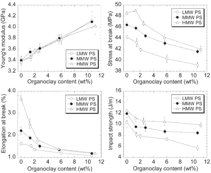
Effects of Polymer Grade on Mechanical Properties Figure 7 displays the mechanical test results (Young’s modulus, tensile strength at break, elongation at break and impact strength) vs. organoclay content for the three PS grades. Young’s modulus increases with organoclay content almost independently of the PS molecular weight. The data (see Eq. 2) suggest low aspect ratio, p ⬇ 28, for the organoclay stacks [9]. It is worth noting that similar calcu-lations for well-exfoliated PNC based on PA-6 give p ⬇ 200. Owing to PA-6 matrix crystallization the latter value was slightly smaller than the value calculated from melt flow data p ⬇ 287 ⫾ 9. In short, the 10-fold smaller aspect ratio of organoclay than what might be expected for
exfo-TABLE 3. Feed rate dependence of the residence time distribution—see Eq. 1.
Parameter Flow from a0 a1 r
t Hopper 33.7 1013 0.9997
2 Hopper 0.018 0.153 0.9953
t Side-feeder 26.3 712 0.9998
2 Side-feeder 0.0571 0.0174 0.9858
FIG. 9. Izod impact strength vs. tensile strength for PS-based PNC containing 0, 2, and 5 wt% organoclay, and prepared under different conditions.
TABLE 2. Residence time at different feed rate for screw speed of N ⫽ 200 rpm and temperature TB⫽ 200°C.
Experiment code
Hopper feed
rate, Q (kg/h) Measurement region
Mean residence time, t (s)
Normalized variance, 2
HS-0-5 5 Side feeder 3 exit 169 0.0605
5 Hopper 3 exit 237 0.0494
HS-0-10 10 Side feeder 3 exit 96.1 0.0591
10 Hopper 3 exit 133 0.0324
HS-0-20 20 Side feeder 3 exit 62.7 0.0578
liated PNC in the PS matrix, indicates the presence of short stacks. In Part 1 [21], the broadening of the XRD peaks suggested the presence of stacks of about 4 clay platelets in PNC containing 5 wt% organoclay. Thus, the aspect ratio based on Young’s modulus points toward a bulk-average interlayer spacing (under both XRD peaks) of d001 ⬇
2.0 nm.
Fornes et al. [27] also reported insensitivity of the Young’s modulus to the matrix molecular weight. The au-thors studied PNC based on PA-6, compounded with or-ganoclay prepared by reacting sodium-MMT with 2-hy-droxyethyl methyl rapeseed quaternary ammonium chloride. Changing the number-average molecular weight from Mn ⫽ 16.4 to 29.2 kg/mol resulted only in a small
change of the PNC modulus.
As shown in Fig. 7, the stress at break increases with PS molecular weight and it decreases with organoclay content. Its relative value (ratio of PNC stress at break to that of neat PS) is nearly independent of PS grade. By contrast, elon-gation at break shows the most dramatic decrease with clay content for PNC based on HMW, more moderate for the MMW and the smallest for LMW. Thus, the relative values for the three matrices would show different behavior. For organoclay content exceeding about 6 wt%, the PNC elon-gation at break is nearly the same for the three PS resins.
Figure 7 shows that Izod impact strength decreases with organoclay content for each PNC series. As in the case of stress at break, the profiles are parallel. Thus, the relative impact strength is nearly independent of PS grade. How-ever, for HMW, MMW, and LMW series, incorporation of 10 wt% organoclay reduces the impact strength of the matrix by about 20, 30, and 45%, respectively. These de-creases are significantly smaller than the 87% reported for PS compounded with 10 wt% of three different types of organoclay [7].
Yoon et al. [18] observed that the impact strength of PC based PNC is proportional to the elongation at break and this relationship is almost independent of the organoclay type. Since both PC and PS are amorphous, it was tempting to see whether this relationship is valid for the PNC spec-imens discussed in this article; Fig. 8 shows these results. The specimens under consideration were prepared under the same conditions, e.g., barrel temperature, feeding rate, screw configuration, screw rotation speed, etc. The depen-dence is not universal, but within each matrix grade there is a high degree of correlation: r ⱖ 0.92. The slopes decrease with Mwof PS. Similar tendency was reported for PC/clay nanocomposites [18].
Better empirical correlation was observed between the impact and tensile strengths. Figure 9 shows this relation-ship for MMW PS-based PNC prepared under various pro-cessing conditions, viz. feed rate, screw configurations, bar-rel temperatures, and organoclay content. The corbar-relation coefficient of linear fitting curve is r ⫽ 0.933. The depen-dence is nearly independent of the matrix grade.
Theoretical Analysis of Young’s Modulus
Several theoretical models have been proposed for Young’s modulus of polymer/clay nanocomposites. De-pending on the original model, these can be assigned to Halpin and Tsai [28] type or Takayanagi et al. [29] type. The difference between these two types is quite significant. The Halpin and Tsai [28] equations were originally derived for continuous fiber composites, while Takayanagi et al. [29] focused on a more general case of two-phase systems with diverse morphology. For example, Brune and Bicerano [30], as well as Hui and Shia [31] started with a simplified the Halpin and Tsai [28] theory in their derivation of PNC tensile modulus relationships. However, since the Halpin and Tsai [28] approach is valid for an idealized, well-oriented systems with filler particles well bonded to the matrix, the new relations may not be fully applicable to PNC with randomly oriented platelets imperfectly bonded to the matrix.
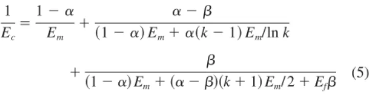
Ji et al. [32] adopted the Takayanagi et al. [29] two-phase model, expanding it into three phases: matrix, interphase, and filler particles randomly distributed in the matrix. These may be of any shape, viz. spherical, cylindrical, or lamellar. The model is fully general, with the three phases connected to each other in parallel and in series. As a consequence, there are two types of interphases, connected to the other phases; one “in parallel” and the other “in series.” In the case of PNC, these may be treated as the interphase inside the stack of clay platelets, and that between the stacks and the matrix. For plate-like filler particles, having thickness tc,
and both length and width ⫽ c(with, c⬎⬎ tc), the Young’s
modulus may be expressed as: 1 Ec ⫽1 ⫺ ␣ Em ⫹ ␣ ⫺  共1 ⫺ ␣兲 Em⫹␣共k ⫺ 1兲 Em/ln k ⫹  共1 ⫺ ␣兲 Em⫹ 共␣ ⫺ 兲共k ⫹ 1兲 Em/ 2 ⫹ Ef (5) where ␣ ⫽ 公[2( /tc) ⫹ 1]Vf;  ⫽ 公Vf; Ec, Emand Ef
are Young’s moduli of composite, matrix and filler, respec-tively, is the thickness of the interfacial region, Vfis the
filler volume fraction and k ⫽ Ei(0)/Em is the ratio of the
interphase modulus on the surface of a particle, Ei(0), to that
of the matrix, Em. For PNC the controlling parameters are:
the size of dispersed particles (tcand c), thickness of the
interfacial region , filler-to-matrix modulus ratio Ef/Em,
and the parameter k. The parameter k represents the ultimate modulus ratio of the interphase to matrix, assuming a linear gradient change in modulus between the matrix and the surface of particle – the value k ⫽ 12 has been arbitrarily chosen [32].
Equation 5 was applied to the experimental values of Young’s modulus reported in this article. The following values of equation parameters were used: Ef ⫽ 170 GPa
[33], Em⫽ 3.4 GPa, tc⫽ 1 nm [34], and k ⫽ 12 [32]. The
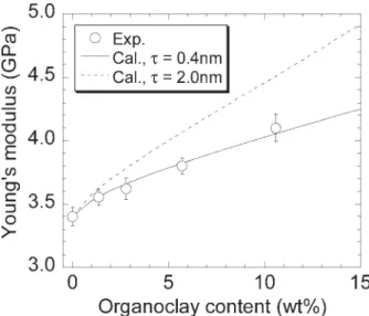
matrix polymer and clay density equal 1040 and 2860 kg/m3, respectively. Results of the computations are shown in Fig. 10 for a series of MMW-PS based PNC.
Experimental data are well described when introducing a thickness of the interphase ⫽ 0.4 nm. This thickness is smaller than, e.g., ⫽ 7.0 nm, calculated by Ji et al. [32] for PA-6 PNC. Although the parameters and k are both material constants, the role of k is not clear. For example, the assumption that k ⫽ 12, 6, and 2 results in ⫽ 0.4, 0.7, and 2.0 nm, respectively. These values of are all smaller than those published for PA-6 PNC, indicating poor exfo-liation of the PS-based PNC. Furthermore, the small thick-ness of the interphase may imply poor interactions between clay platelets and polymer matrix.
In short, the thickness of the interphase cannot be quan-titatively determined from the Ji et al. [32] model. The modulus of the organic phase adsorbed on the high-energy surface of crystalline MMT platelet is known [35] to be high, but value of the ratio k may vary with the system. However, this model provides the correct tendency of the interphase contribution.
CONCLUSION
PS based nanocomposites with commercial organoclay were prepared by melt compounding in a TSE. In this third part, we discuss the effects of the melt compounding vari-ables as well as the matrix resin molecular weight and organoclay content on the mechanical performance of pro-duced PNC.
Optimum PNC performance results from two competing processes: the shear dispersion of organoclay platelets and the thermomechanical degradation of the intercalant. Barrel temperature and screw configuration had a little influence
on the tensile properties and impact strength. According to the overall experimental results, milder compounding con-ditions (low-shear screw configuration and lower barrel temperature; 180°C in this study) provided marginally bet-ter performance than the high-shear screw.
An increase of residence time reduced the height of the first XRD peak and increased that of the second peak. Long compounding time reduced the degree of clay dispersion and mechanical performance. Adjusting the residence time in the extruder optimized the mechanical properties. How-ever, owing to the thermomechanical degradation effects varying the compounding conditions resulted in relatively minor overall improvement of the PNC performance.
Young’s modulus increased with organoclay content, almost independently of the matrix molecular weight. The stress at break and impact strength decreased with organo-clay content and increased with PS molecular weight. Their relative parameter values (i.e., PNC parameter divided by that of the matrix) showed similar dependence.
Young’s modulus and impact strength decreased with residence time. Similar tendencies were observed for other tensile properties. Since the slopes of these dependencies for PNC are similar to that of the neat PS, the matrix degrada-tion seems to play the major role.
Relationship between impact strength and elongation at break of PNC, prepared under same compounding condi-tions, showed strong dependence on matrix grade. How-ever, better empirical correlation was observed between the impact and tensile strengths.
The Young’s modulus vs. organoclay content depen-dence was analyzed using the multiphase model, recently proposed by Ji et al. [32]. Fitting the experimental data to the model predictions indicated narrow interphase thick-ness, ⫽ 0.4 nm, i.e., approximately 17.5 times smaller than that calculated for PA-6 PNC. The thin interphase indicates poor exfoliation in the PS-based PNC, and weak interactions between clay and the PS matrix.
ACKNOWLEDGMENTS
We thank Mr. Yves Simard, NRCC/IMI for melt com-pounding and preparation of pecimens for tensile and im-pact tests, and Prof. Jørgen Lyngaae-Jørgensen, Technical University of Denmark, for the measurement of organoclay content by TGA. Mr. S. Popławski, McGill University, Dept. of Metallurgical Engineering, made the XRD mea-surements. NOVA Chemicals supplied the polystyrene res-ins.
NOMENCLATURE
a0 Constant of Eq. 1 a1 Constant of Eq. 1 D Screw diameter (mm)
d001 Interlayer spacing of clay (nm) FIG. 10. Young’s modulus vs. organoclay content for MMW-PS based
PNC. Experimental values are shown as points, and the Ji et al. [32] model predictions as lines: solid and broken for the interface thickness of ⫽ 0.4 and 2.0 nm, respectively. Other parameters are: Ec⫽ 170 GPa, Em⫽ 3.4
d001 Bulk-average interlayer spacing (nm) E(t) Residence time distribution
Ec Young’s modulus of composite (GPa)
Ei(0) Interphase modulus on the surface of a particle (GPa)
Ef Young’s modulus of filler (GPa) Em Young’s modulus of matrix (GPa)
k Ratio of the interphase modulus on the surface of a particle to that of the matrix
L Screw length (mm)
Mn Number average molecular weight Mw Weight average molecular weight N Screw rotation speed (rpm) p Aspect ratio of a clay platelet Q Feed rate (kg/h)
r Correlation coefficient
t Time (s)
t Mean residence time (s)
tc Thickness of plate-like filler particles (nm) TB Barrel temperature (°C)
Vf Filler volume fraction w Organoclay content (wt%) X-ray diffraction angle (deg) Wavelength of X-ray radiation (nm) Frequency of ultrasonic (MHz)
c Length or width of plate-like filler particles (nm)
2 Normalized variance of the mean residence time Thickness of the interfacial region (nm)
REFERENCES
1. A. Okada and A. Usuki, Mater. Sci. Eng. C, 3, 109 (1995). 2. N. Hasegawa, M. Kawasumi, M. Kato, A. Usuki, and A.
Okada, J. Appl. Polym. Sci., 67, 87 (1998).
3. P. Reichert, H. Nitz, S. Klinke, R. Brandsch, R. Thomann, and R. Mu¨lhaupt, Macromol. Rapid Commun., 275, 8 (2000). 4. E. Manias, A. Touny, L. Wu, K. Strawhecker, B. Lu, and T. C.
Chung, Chem. Mater., 13, 3516 (2001).
5. X. Liu and Q. Wu, Macromol. Rapid Commun., 287, 180 (2002).
6. N. Hasegawa, H. Okamoto, M. Kawasumi, and A. Usuki,
J. Appl. Polym. Sci., 74, 3359 (1999).
7. H. Wang, C. Zeng, M. Elekovitch, L. James Lee, and K.W. Koelling, Polym. Eng. Sci., 41, 2036 (2001).
8. C.I. Park, O.O. Park, J.G. Lim, and H.J. Kim, Polymer, 42, 7465 (2001).
9. L.A. Utracki, Clay-Containing Polymeric Nanocomposites [2 volume monograph], RAPRA, Shropshire, UK (2004). 10. H.R. Dennis, D.L. Hunter, D. Chang, S. Kim, J.L. White, J.W.
Cho, and D.R. Paul, Polymer, 42, 9513 (2001). 11. J.W. Cho and D.R. Paul, Polymer, 42, 1083 (2001). 12. H.H. Kausch and M. Tirrell, Ann. Rev. Mater. Sci., 19, 341
(1989).
13. N. Hasegawa, H. Okamoto, M. Kato, A. Usuki, and N. Sato,
Polymer, 44, 2933 (2003).
14. Y. Wang, F.-B. Chen, and K.-C. Wu, J. Appl. Polym. Sci., 93, 100 (2004).
15. W. Giannelis, G. Camino, N.T. Dintcheva, S. Lo Verso, and F.P. LaMantia, Macromol. Mater. Eng., 289, 238 (2004). 16. R.K. Shah and D.R. Paul, Polymer, 45, 2991 (2004). 17. L. Incarnato, P. Scarfato, G.M. Russo, L. Di Matio, P. Iannelli,
and D. Acierno, Polymer, 44, 4625 (2003).
18. P.J. Yoon, D.L. Hunter, and D.R. Paul, Polymer, 44, 5323 (2003).
19. P.J. Yoon, D.L. Hunter, and D.R. Paul, Polymer, 44, 5341 (2003).
20. A. Yasmin, J.L. Abot, and I.M. Daniel, Scripta Mater., 49, 81 (2003).
21. S. Tanoue, L.A. Utracki, A. Garcia-Rejon, J. Tatiboue¨t, K.C. Cole, and M.R. Kamal, Polym. Eng. Sci., 44, 1046 (2004). 22. S. Tanoue, L.A. Utracki, A. Garcia-Rejon, P. Sammut, M.-T.
Ton-That, I. Pesneau, M.R. Kamal, and J. Lyngaae-Jørgensen,
Polym. Eng. Sci., 44, 1061 (2004).
23. A. Usuki, M. Kato, A. Okada, and T. Kurauchi, J. Apply.
Polym. Sci., 63, 137 (1997).
24. R. Gendron, L.E. Daigneault, J. Tatiboue¨t, and M.M. Dumou-lin, SPE ANTEC Tech. Papers, 40, 167 (1994).
25. M. Marcotte, M. Trigui, J. Tatiboue¨t, and H.S. Ramaswamy, J.
Food Sci., 65, 1180 (2000).
26. R.A. Vaia, K.D. Jandt, E. Kramer, and E.P. Giannelis,
Mac-romolecules, 28, 8080 (1995).
27. T.D. Fornes, P.J. Yoon, H. Keskkula, and D.R. Paul, Polymer,
42, 9929 (2001).
28. J.C. Halpin and S.W. Tsai, Air Force Mater. Res. Lab. Tech.
Rep., AFML-TR-67-423 (1967).
29. M. Takayanagi, S. Vemura, and S. Minami, J. Polym. Sci.
Part C, 5, 113 (1964).
30. A. Brune and J. Bicerano, Polymer, 43, 369 (2002). 31. C.Y. Hui and D. Shia, Polym. Eng. Sci., 38, 774 (1998). 32. X.L. Ji, J.K. Jing, W. Jiang, and B.Z. Jiang, Polym. Eng. Sci.,
42, 983 (2002).
33. D. Shia, C.Y. Hui, S.D. Burnside, and E.P. Giannelis, Polym.
Compos., 19, 608 (1998).
34. M. Kato and A. Usuki, Polymer-Clay Nanocomposites, T.J. Pinnavaia and G.W. Beall, eds., John Wiley & Sons, New York (2001).
35. G. Luengo, F.-J. Schmitt, R. Hill, and J.N. Israelachvili,