PFC/JA-82-14
Analysis of Toroidal Magnet Systems on the Basis of
The Reissner Shell Theory
E.S. Bobrov, J. H. Schultz
Francis Bitter National Magnet Laboratory
Plasma Fusion Center
Massachusetts Institute of Technology,
Cambridge, MA 02139
ANALYSIS OF TOROIDAL MAGNET SYSTEMS ON THE BASIS OF THE REISSNER SHELL THEORY
E.S. Bobrov, J.H. Schultz
Francis Bitter National Magnet Laboratory Plasma Fusion Center
Massachusetts Institute of Technology Cambridge, Massachusetts 02139
ABSTRACT
A method for analyzing the structural behavior of toroidal magnet systems subjected to Lorentz fomes both in and out of the winding planes, and thermal loads is considered in this paper. The toroidal coil assembly is treated as a finite thickness, ortho-tropic, rotationally symmetric shell of revolution acted upon by symmetrical and antisymmetrical loads. The equations based on Reissner's shell theory are derived, and numerical solutions are presented. The method is an efficient design tool for the analysis and shape selection of toroidal magnet systems and their structures, such as the in-plane and out-of-plane load support systems for closed magnetic con-finement machines, e.g. tokamaks, stellarators, and bumpy tori. NOMENCLATURE B t B v 1, 2, 3 F z 12, 13, 23 h M M2, M12,M21 N
N N N
1,
2, 12, 21
N
Ql
,Q1,
2
q2, q3
r 1R
1,R 2
S
toroidal magnetic field, T vertical magnetic field, T Young's moduli, N/m2 vertical force, N 2 shear moduli, N/m shell thickness, m electric current, A
Contributed by the Pressure Vessel & Piping Division
T,T T
u,v,w
za
a2
1, 2
Y1 2,y 1 3, Y2 3yl13m,
y23m
1, 2, 3 stress couples, Nm/m number of toroidal turnsmembrane stress resultants,
N/m
transverse shear resultants, Rim
distributed shear and normal loads,
N/m2
toroidal radius, m
principal radii of curvature of middle surface, m distance measured along the
meridian, m
temperature increment and temperature resultants, 'C components of midsurface
displacement, m
midsurface normal coordinate coefficients of thermal
ex-pansion
angles of midsurface rotation shear strains
effective transverse shear strains
0
K K K1,
2, 12
P 0 12, 13, 231,
02,a
3 T T t12, 13, 23
Q
tangent of angle of meridian effective midsurface
curva-ture changes magnetic permiability of
vacuum,
H/m
Poisson's ratios axial stresses shear stresses equatorial coordinateLagrangean multiplier
func-tion
INTRODUCTION
This paper presents equations of orthotropic, rotationally symmetric toroidal shells of finite thickness subjected to symmetrical and antisymmetri-cal loads, including thermal loads. These equations were derived using the approach developed by E.
Reissner
(1)
that allows to take into account the
ef-fect of transverse stresses on the deformation of the middle surface of the shell and consistently omit terms which are small of order h2/R2.The equations are used to model the structural
behavior of discrete and continuous toroidal field
(TF) magnet systems subjected to in-plane and out-of-plane Lorentz forces and experiencing orthotropic
thermal expansion or contraction.
The utilization of the theory of orthotropic shells of finite thickness for the structural analy-sis of the TF magnet systems is found to be very
ef-ficient
,particularly in the process of initial
shape selection.
The earliest and the most popular TF coil con-figuration, known as the Princeton D shape, was first derived in (2) by considering the equilibrium of a plane filament in pure tension subjected to a distri-buted normal load inversely proportional to the toroidal radius. The inner leg of this coil is sup-ported by a stiff cylinder to react the unbalanced centering force. As shown by several authors (3-5) substantial bending stresses are revealed by detailed analyses of TF magnet structures designed to follow the pure tension trajectory. Large bending stresses were also found in the compound-constant-tension coil configurations derived in (6). These bending stresses were partially explained by several factors, includ-ing the finite thickness of the coils in real tokamak structures , nonuniformity of the toroidal field due to the discrete character of coil placement(8) and the violation of the compatibility conditions at the joining points of different "pure tension" shapes (9). Almost no consideration was given to the effect of the intercoil structure (to support the out-of-plane loads) on the coil shapes.
An important contribution in the modelling of toroidal magnet systems was the membrane shell model developed by Gray et al (10) which took into
consideration the circumferential stiffness of the magnet assembly. A bending free membrane shell shape was derived. It was substantially different
from that of a constant tension filament. Unlike the significant shape deviations described in (11) and (12), the deviation from the D trajectory happens in the membrane shell consideration naturally, inde-pendent of reaction forces or finite thickness ef-fects. Unfortunately, there is an inherent strain incompatibility at the crown of a toroidal shell in the solution to the linear membrane theory (13). This incompatibility introduces bending stresses in a shell with finite bending stiffness, as demon-strated below.
This analysis and design studies (14) call into question the entire approach of searching for an op-timal shape to minimize bending stresses. The an-alysis presented in this paper shows that typical tokamak reactor designs (14) with sufficient struc-tural case material to withstand tensile stresses have sufficient bending stiffness to react the bend-ing stresses, which were found to be less than 50% of primary membrane stresses, for the two shapes con-sidered. Furthermore, design studies (14) of high-cycle, inductively driven tokamaks showed that case thicknesses were dominated by pulsed out-of-plane loads. The possibility of low-cycle operation for all the major toroidal confinement systems requires a capability for the rapid scoping of complex inter-related structural and physics trade-offs which is
substantially advanced by the inclusion of the out-of-plane load induced stresses in the model describ-ed below.
BASIC EQUATIONS
Following E.
Reissner(l)
we derived a basic set of equations of rotationally symmetric ortho-tropic shells of revolution of finite thickness. The equations take into account the effect of transverse stresses on the deformation of the middle surface of the shell and retain terms of order h/R in compari-son with unity. This is essential with an h/R ratio greater than 1/20. In order to distinguish the structural response of toroidal coil systems to sym-metrical (normal pressure due to the toroidal field, and temperature variation) and antisymmetrical (tor-sional shear due to the vertical field) loads, the equations are presented in two respective groups of which the first corresponds to the symmetrical load and the second to the antysimmetrical load.Symmetrical Load
In this case the shell is subjected to a me-chanical pressure caused by toroidal field Bt
2
2
3 8Tr r
and rotationally symmetric temperature distribution T(s,z). The temperature distribution in the shell is accounted for in the usual manner by means of the integrated temperature effect of the form
h
T (s) = - T(s,z)dz 0 hJh
h22
T(s) =zT(s,z)dz
h
h
2
(2)
(3)
2
(1)
d q
2N
M
M
21
Qi+
dQ
q
Q
+dMj
M
2N2
de
Ni+ dNj
Rd6
R2
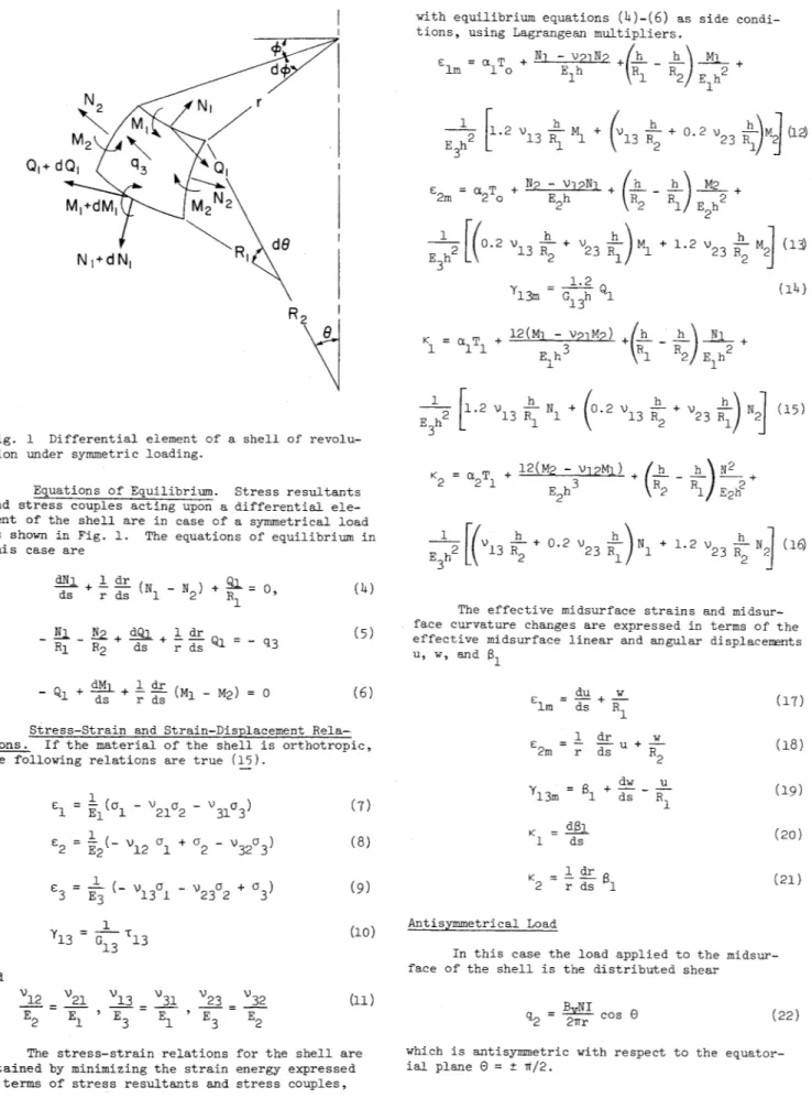
Fig. 1 Differential element of a shell of revolu-tion under symmetric loading.
Equations of Equilibrium. Stress resultants and stress couples acting upon a differential ele-ment of the shell are in case of a symmetrical load as shown in Fig. 1. The equations of equilibrium in this case are
l
dr (N -N )+
.i=
0
(4)ds
r ds
1
2
R
1
N1
Ea + d
l
dr
(5)
R
R2
ds +Qi
= -q
3with equilibrium equations (4)-(6) as side
condi-tions, using Lagrangean multipliers. a
=T
+ NI - vp2N + - h M,im
lo
E
1h
R
1
R2
E
h2
.2 v_L
M,
+v
2-
+0.2v
M() E2
1 3 R + 13R2
02
23 2) =a
T +Np
-VpN
+ (h_ h_) M2 +2m
2
o
E
2h
2hl
2 2h0.2
vl
2L3 M
+
1
02
Fl'
+
'2
3
+E h
2L
13
R
2
1)
~lm
1.2
K =T +12(M+
-VplM2)+1
11
E
h
1.2
v2 3_-
M
(13)
(14)
h2/)
E
1h2+
J2 21-
N
+0.2
1 3 +V
2 3NJ
(15)
K =T
+ 12(M2 -vl2M1)
+h
2
21
3
R
E
h
\2
l
E2kT1
V
+0.2
V
-L)
N
+1.2
vN
(16
E h
21B
3R2
23
R
l
23
R
2 iThe effective midsurface strains and midsur-face curvature changes are expressed in terms of the effective midsurface linear and angular displacements
u, w, and
B
+
+
+r- (Ml - M2) =0
(6)
Stress-Strain and Strain-Displacement Rela-tions. If the material of the shell is orthotropic, the following relations are true (15).
E= 1(' -v 0 a-V 0
E
11
21 2
31 3
E
23E
-(-v
0 +0 - V12 1
2
32 3
a
=-(T
0-0±)3
E
3131
1
Y 3G1 -T112
21
E
2E
1 V13 _31
'E
3
(7)
(8)
(9)
(10)
(11)
V23 V32
'E
3
E2
The stress-strain relations for the shell are obtained by minimizing the strain energy expressed in terms of stress resultants and stress couples,
lm
=
+
_ Kim dsR11
drw t 2m r ds u +6lm
dw
u
Y13m
"1
+ -R1=
d
l
1
ds
(17)
(18)
(19)
(20)
(21)
K1 dr
2
r
ds1
Antisymmetrical LoadIn this case the load applied to the midsur-face of the shell is the distributed shear
=
vI cos 8
(22)
2
2Trr
which is antisymmetric with respect to the equator-ial plane
8 =
±1/2.d
r
N21
N1r2
M21
2
Q2q2
M12+dM.,
12
N
12
+dN
12
M21
Rde
R2
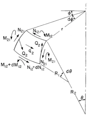
Fig. 2 Differential element of a shell of revolu-tion under antisymmetric loading.
Equations of Equilibrium. Tn case of an anti-symmetrical distributed shear load (22) only shear stress resultants and shear stress couples are gen-erated in the shell as shown in Fig. 2. The equili-brium of the shell is described by the following four equations. dN2
~1
dr ds r -d12
+N
21 + . - 2 dM12+
d
2+ M/
2
ds
r.ds
k12
21)
N -N + - =0
12 21R
R2
12 21 2(23)
(24)
K12 3 (M1 2 + M2 1) (30) 12Utilization of the four equilibrium equations (23) - (26) by means of the Lagrange multiplier method leads to expressions for the effective midsur-face shear strain and curvature variations in terms of the effective midsurface linear displacement v and angular displacement 2' 1/dv 1ldr N h2I 1 £ -
}
v I) -- D (31) 12m 2 ds r)ds Rl31) +241
+
1
d+r'
6
2 \ds r ds )=
1
d2
1
dr12
2 ds r ds 2)(33)
Y23m
2-X
2 R (314)NUMERICAL IMPLEMENTATION AND RESULTS
The solutions to the equations presented above, with appropriate boundary conditions give a complete description of the behavior of an orthotropic shell of revolution, of finite thickness.
In order to obtain the necessary quantities
1 1 and
1
drR
1R2
r
dswhich enter as coefficients into equations, the me-ridian of the shell should be described as a function (25) of *s or r, either analytically or in a tabulated form
The geometrical identities used to describe the (26) shell of revolution are:
(32)
Stress-Strain and Strain-Displacement
Rela-tions. The constitutive relationships (Hooke's law) if only shear strains and stresses are involved are expressed for an orthotropic material in the form1 1
' 2=G12 T1 23=G23 T2 (27)
Minimization of the shear strain energy ex-pressed in terms of shear stress resultants N12, N2 1,
Q23 and shear stress couples M12 and M21 yields three
constitutive relationships _2m = 4G2h 12 1 h (N1 2 2 + N2 121) (28)
Y2m=1.2
Q
23m G23h 2(29)
=
00s
6C
ds1
_ d(sin8)
R
dr(35)
(36)
(37)1
sin
e
2A computer code for the finite difference so-lution of the two groups of equations corresponding to symmetrical and antisymmetrical loadings has been developed. In order to complete the analysis, the code requires the analytical or tabulated expres-sion for the shape of the meridian in the form
sin e
=
f(r)
(38)
along with the inner and outer toroidal radii, ef-fective material physical properties, and the number of ampere-turns.
The meridian shapes presented here as examples are a. circle and the "bending free" shell of Gray et al (10). Both shells have dimensions of the tor-oidal field coils in the Fusion Engineering Device
(FED) described in (14), i.e., rin
=2.14
m,
rout = 10.5 m, NI = 115 MAT, effective shell thick-ness h =
0.66
m and a coil case thickness 0.08 m. Figure 3 shows the meridians of the circular and "bend.ing free" shells analyzed in this paper, along with that of a Princeton D.4.
0
L
z/rin
PRINCETON
D
16or
-120
a - 80 U) U)S40
u) 2 'Ca
0 CIRCULAR TORUS A "BENDING FREETORUS -p -r
t~..A I STRESS NTIAL STRESS rin S01 i-4 ''0 -MERIDIONAL ---CIRCUMFERE80
-
-120-Fig. 4 Effective membrane stresses in circular and "bending free" coil structures with FED dimensions.
6 0
r
D_
40
20
U) -0 (0 zM-40
3.94
4.92
Fig. 3 Meridians of circular, "bending free", and Princeton D tori for FED aspect ratio.
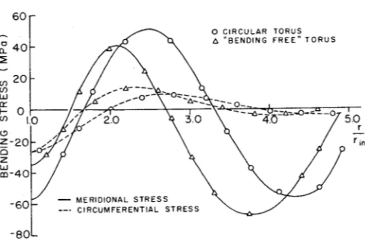
The results of the analyses are presented in Fig.
4
and Fig. 5. Figure 4 shows the distribution of the effective meridional and circumferential mem-brane stresses in the coils and intercoil structures of both shapes. The effective meridional and circum-ferential bending stresses in the extreme fibers of the structural elements are as shown in Fig. 5. For the circular configuration the primary tensile stress at the inner leg at the equator is 151 MPa while the peak bending stress is 54 MPa. For the "bending free" configuration, the primary tensile stress in the inner leg at the equator is 139 MPa, while the peak bending stress is66
MPa.This demonstrates that if the finite thickness of the magnet structure is accounted for the "bend-ing free" configuration proposed in (10) has bend"bend-ing stresses which are proportionally as large as the bending stresses in the circular configuration.
Since the total upward force on the upper half of the coil system must be
F = vo(NI)
2
(39)
Fz
47T
rin(9)
or 2122 MN, the theoretical minimum tension is 1061 MN in the inner leg, giving an average stress of 120 MPa in an ideal constant tension coil. Thus, the tensile stress in the inner leg at the equator for
0
CIRCULAR TORUSA
"BENDING FREE" TORUS0
7
/X2.3.0
~
4O
5.0
io'.
- MERIDIONAL STRESS CIRCUMFERENTIAL STRESS
-80L
Fig. 5 Effective bending stresses in the extreme fibers of circular and "bending free" coil struc-tures with FED dimensions.
circular coil is 1.26 times the theoretical minimum, while the tensile stress for the "bending free" con-figuration is 1.16 times the theoretical minimum. The primary stress in the "bending free" shape is
8.5%
smaller than that in the circle, while theperimeter of the "bending free" configuration is 18%
greater than that of a circle, implying that the circular configuration requires less mass for a given set of stress allowables.
CONCLUSIONS
An efficient method of analysis of toroidal magnet structures of arbitrary configuration, and subjected to electromechanical and thermal loads has been developed and numerically implemented.
It has been found that due to the finite thick-ness of realistic magnet structures and discontinuity of the displacement field present in the linear mem-brane theory the "bending free" shell configuration derived in (10) has bending stresses.
The whole concept of shape optimization based on minimization of bending stresses is called into
3.0
2.0
1
.0
I
1.98
2.96
r /ri
C
"BENDING FREE"
-
CIRCLE
-60question. The design strategy of simply making the
toroidal field coils circular or as small as possible,
within the constraints of reactor assembly and main-tenance can be recommended as an alternative. Re-actor concepts with all external vertical field coils could be substantially reduced in weight and cost by using low profile coils.ACKNOWLEDGMENTS
This work was supported by the
Office
of Fusiac Energy, U.S. Department of Energy, under contract DOE/ET-51013-31. The Francis Bitter National Magnet Laboratory receives support from the National Science Foundation.REFERENCES
1 Reissner, E., "On Some Problems in Shell Theory," Structural Mechanics, Proceedings of the First Symposium on Naval Structural Mechanics,
Per-gamon Press, New York, 1960, pp. 74-113.
2 File, J., Mills, R.G., and Sheffield, G.V., "Large Superconducting Magnet Designs for Fusion Re-actors," IEEE Transactions of Nuclear Science, NS-18,
1971, pp. 277-282.
3 DeMichele, D.W., Darby, J.B., Jr., "Three-Dimensional Mechanical Stresses in Toroidal Magnets for Controlled Thermonuclear Reactors," Proceedings of the Fifth Symposium on Engineering Problems of Fusion Research, 1974, pp. 558-569.
4 S611, M., "Comparison of Some Analytical and
Numerical Calculated Parameters for Toroidal Field Coils," IPP 4/145, Nov. 1976, Max-Plank Institute for Plasma Physics, Munich, Federal Republic of Germany.
5 Diserans, N.J., "Stress Analysis Studies in Optimized 'D' Shaped Tokamak Magnet Designs," RL-75-117, July 1975, Rutherford Laboratory, Chilton,
Didcot, Oxon, England.
6 Gralnick, S.L., and Tenney, F.H., "Analytic Solutions for Constant Tension Coil Shapes," Journal of Applied Physics, Vol..
47,
No. 6, June 1976, pp.2710-2715.
7 Weissenburger, D.W., Christensen, U.R., Bialek, J., "Pure Tension Shape of a Thick Torus," PPPL-1353, July 1977, Princeton Plasma Physics Lab-oratory, Princeton, N.J.
8 Moses, R.W., and Young, W.C., "Analytical
Expressions for Magnetic Forces on Sectored Toroidal
Coils," Proceedings of the Sixth Symposium on En-gineering Problems of Fusion Research, 1976, pp.
917-921.
9 Gralnick, S.L., Ojalvo, I.U., Zatz, I.J., and Balderes, T., Nuclear Technology, Vol. 45, No.
10, October 1979, pp. 233-243.
10 Gray, W.H., Stoddart, W.C.T., Akin, J.E., "A Derivation of a Bending Free Todoidal Shell for
Tokamak Fusion Reactors,"Journal of Applied
Me-chanics, Vol.
46,
March 1979, pp. 120-124.
11 Welch, C.T., "Bending-Free Shapes for Tor-oidal Magnet Field Coils with Concentrated Symmetric Reactions," Proceedings of the Sixth Symposium on
Engineering Problems of Fusion Research, 1976, pp.
410-913.
12 Ojalvo,
I.U.,
and Zatz, I.J., "Structural
Support Design Method for Minimizing In-Plane TF
Coil Stresses," Proceedings of theEighth Symposium on Engineering Problems of Fusion Research, 1980,
pp. 1463-1468.
13 Fligge, W., Stresses in Shells, 2nd Ed.,
Springer-Verlag, Berlin, 1973.
14 Flanagan, C.A., Steiner, D., Smith, G.E., Fusion Engineering Design Center Staff, "Fusion En-gineering Design Description," Vol. 1, ORNL/TM-7948/