Sylvain R. Duc Juerg Hodler Marius R. Schmid Marco Zanetti Bernard Mengiardi Claudio Dora Christian W. A. Pfirrmann Received: 13 April 2005 Revised: 15 June 2005 Accepted: 5 July 2005
Published online: 16 August 2005
# Springer-Verlag 2005
Prospective evaluation of two different
injection techniques for MR arthrography
of the hip
Abstract The aim of the study was to evaluate prospectively the technical feasibility and discomfort of two different injection techniques for MR arthrography of the hip. Sixty-one consecutive patients undergoing MR arthrography of the hip (68 hips) were randomly injected either at the femoral head (36 hips) or the femoral neck (32 hips). The patients rated discomfort during and 0–72 h after arthrography using a visual analogue scale (VAS, 0=“did not feel anything”, 100=“un-bearable”). The volume injected, the distance between the needle tract and the neurovascular bundle, the duration of the procedure and the extra-articu-lar contrast leakage were measured. No significant differences were found for the volume injected, the distance between the needle tract and the neu-rovascular bundle, or the procedure duration. Volume of extra-articular contrast leakage was statistically
sig-nificantly different (head 1±2 cm3, neck 3±5 cm3, P=0.024). The VAS score for needle advancement was significantly different (head 25±20, neck 19±23, P=0.031). No significant differences were found for the VAS score regarding delayed discomfort. Before the examination the arthrogra-phy-related discomfort was overesti-mated by 74% (50/68), correctly anticipated by 22% (15/68) and un-derestimated by 4% (3/68) of the patients. MR-related discomfort was overestimated by 32% (22/68), cor-rectly anticipated by 57% (39/68) and underestimated by 10% (7/68) of the patients. Both hip puncture techniques were well tolerated. The neck injec-tion technique produced less discom-fort and was associated with greater extra-articular contrast leakage. Keywords Hip . Arthrography . Technology
Introduction
MR arthrography of the hip is gaining interest for the evaluation of labral and cartilaginous lesions of the hip. With the performance of increasing numbers of intra-articular contrast injections, information about patients’ tolerance of this procedure becomes more important.
A large variety of injection techniques for hip arthrog-raphy has been described in the literature. The commonly described techniques include an inferomedial approach, mostly used in pediatric patients [1–4], a lateral supra-trochanteric approach [5–8] and a straight anterior ap-proach, targeting the femoral head either immediately below the acetabular rim [9], at the centre of the femoral neck [6, 9–13], at the inferior [7, 14] or superior [15]
border of the neck. Further injection techniques using the anterior approach are performed with cephalad [5,7, 16] or caudal angulation [7] of the needle. The success rate for hip arthrography using anatomic landmarks exclusive-ly is onexclusive-ly 52–80% [5, 17]. In our institution the straight anterior approach, targeting the femoral head supero-lat-erally, and the straight anterior approach, targeting the central portion of the femoral neck, are both routinely used. The straight anterior approach is preferred to the oblique or lateral approach because this approach parallels the X-ray beam and has the shortest distance between the skin and the joint. However, it is not clear which technique is better tolerated by the patients.
The purpose of the present study was to evaluate pro-spectively the technical feasibility and discomfort of two S. R. Duc (*) . J. Hodler .
M. R. Schmid . M. Zanetti . B. Mengiardi . C. W. A. Pfirrmann Department of Radiology,
University Hospital, Balgrist, Forchstrasse 340, 8008 Zurich, Switzerland e-mail: [email protected] Tel.: +41-1-3863308 Fax: +41-1-3863319 C. Dora
Department of Orthopaedic Surgery, University Hospital, Balgrist, Forchstrasse 340,
different anterior injection techniques, with targeting of either the femoral head or the femoral neck.
Materials and methods Patients
Between June 2004 and October 2004, 61 consecutive patients (mean age 40 years, range 18–73 years; 30 men, 31 women) referred for MR arthrography of the hip were prospectively included in the study. Seven patients un-derwent bilateral MR arthrography. Therefore, 68 hips were examined. The patients were addressed for the eval-uation of labrum and cartilage lesions. The study proto-col was approved by the hospital’s institutional review board. Written informed consent was obtained from all patients. Inclusion criteria were: adult patients and suf-ficient knowledge of language to understand the study protocol. Patients with prior hip surgery were excluded. The hips were randomly assigned for puncture site at either the femoral head (n=36 hips) or the femoral neck (n=32 hips). The patients were blind to the arthrographic approach.
Arthrography
The patients lay in a supine position on the fluoroscopy table (digital multipurpose C-arm system, Toshiba Ulti-max ADR-1000A, Toshiba Medical Systems, Tokyo, Japan). The hip to be injected was elevated by 10° with a hard foam wedge. The orientation of the tube detector unit was vertical.
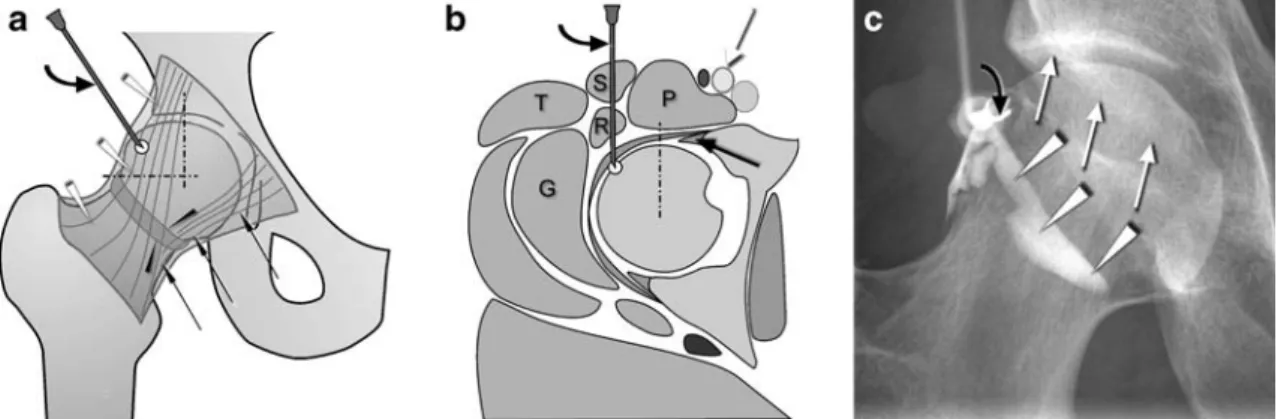
The target site for the femoral head injection was locat-ed at the lateral aspect of the supero-lateral quadrant of the femoral head (Fig.1). The needle was advanced until the tip reached the cartilage of the femoral head.
The target point for the femoral neck injection was the midpoint between the superior and inferior outline of the femoral neck, the base of the femoral head and the inter-trochanteric line (Fig. 2). The needle was advanced until the bone of the femoral neck was reached.
The puncture was performed by one of the five ra-diologists experienced in joint injections, in a standard-ized fashion. The skin was disinfected and covered with sterile drapes. A 70 mm long 20 G needle was used for the procedure. A maximum of 2 ml of scandicaine 2% was used for anaesthesia of the needle path. The needle was advanced under fluoroscopic control. Intra-articular position of the needle tip was verified by the injection of a maximum of 2 ml of iodinated contrast. A mean of 10 ml (2 mmol/l gadoterate meglumine, Dotarem, Guerbet, Paris, France) was then instilled (minimum 3 ml, maximum 15 ml). After the injection the puncture site was marked with a nitroglycerine capsule so that the needle tract could be precisely located during the following MR examination.
MRI
MR examination was performed either on a 1.0 Tesla scanner (Expert impact, Siemens, Erlangen, Germany) or on a 1.5 Tesla scanner (Symphony, Siemens).
In addition to the standard hip imaging protocol used in our institution, a T1-weighted SE fat-saturated trans-verse sequence (TR 420, TE 12, FOV 220, matrix:
Fig. 1 Femoral head injection technique. a Schematic drawing of the target site at the lateral aspect of the supero-lateral quadrant of the femoral head. The dotted lines delineate the supero-lateral head quadrant. The straight black arrows demonstrate the pubofemoral ligament, the white arrowheads the iliofemoral ligament, the black arrowheads the zona orbicularis (curved arrow needle). b Schematic drawing in the axial plane demonstrating the target point at the lateral aspect of the supero-lateral quadrant of the femoral head. Note the distance to the neurovascular bundle (white arrow) and to the anterior labrum (straight black arrow). (S sartorius muscle, R
rectus femoris muscle, P psoas muscle, T tensor fasciae latae, G gluteus minimus muscle, curved arrow needle, dotted line delim-itation of the supero-lateral quadrant towards the supero-medial quadrant of the femoral head). c Corresponding radiograph dem-onstrating the needle (curved arrow) at the supero-lateral quadrant of the femoral head. The intra-articular contrast material (white arrowheads) outlines the zona orbicularis. Note the safety distance from the needle to the anterior wall of the acetabulum (white arrows)
384×384, slice thickness 10 mm) was acquired on both scanners to visualize the skin marker at the puncture site and contrast leakage into soft tissue.
Evaluation of technical factors
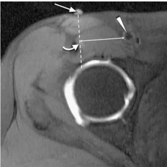
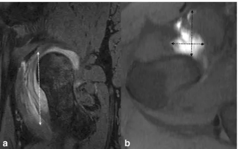
The time between skin prick and needle removal was measured by the technician with a stop watch. In order for the distance of the needle tract to the femoral neu-rovascular bundle to be measured, a line was drawn through the skin marker on the T1-weighted SE fat-sat-urated transverse image to the target point. A line per-pendicular to this reference line was then drawn through the femoral artery, and the distance between artery and reference line was measured on the PACS screen (Image Devices, Idstein, Germany) to the nearest millimetre by one of the authors (Fig. 3). The extra-articular contrast leakage was evaluated on axial and sagittal fat-saturat-ed images by the same observer. The maximum extent was determined in all three planes. The volume (mm3) was calculated with the following formula: cranio-cau-dal extent (millimetres) × antero-posterior extent (mil-limetres) × medio-lateral extent (mil(mil-limetres) divided by 2, which approximates an ellipsoid (Fig. 4).
Evaluation of discomfort
Discomfort during and after the procedure was evaluated with a visual analogue scale (VAS). The left anchor (0) represented “did not feel anything” and the right anchor (100) was defined as“unbearable pain”.
After arthrography the VAS scores were obtained for skin pricking, needle advancement, and injection of
intra-articular contrast material. Residual discomfort was as-sessed immediately after the MR examination. For fol-low-up the participants received a questionnaire with a prepaid and addressed envelope. They were asked to rate their residual pain 12 h, 24 h, 48 h, and 72 h after arthrography.
Fig. 3 Measurement of the distance to the neurovascular bundle. T1-weighted SE fat-saturated transverse image illustrating the measurement of the distance between the puncture path (dashed line) and the femoral artery (arrowhead). The reference points for the path are the skin marker (straight arrow) and the subtle contrast product deposition found along the path (curved arrow). The shortest distance (double-headed arrow) between the puncture path and the femoral artery was measured
Fig. 2 Femoral neck injection technique. a Schematic drawing of the target site at the midpoint between the superior and inferior outline of the femoral neck, the base of the femoral head (medial dotted line) and the intertrochanteric line (lateral dotted line). The straight black arrows demonstrate the pubofemoral ligament, the white arrowheads the iliofemoral ligament, the black arrowheads the zona orbicularis (curved arrow needle). b Schematic drawing in the axial plane demonstrating the target point at the femoral neck. Note the distance from the needle (curved arrow) to the
neurovas-cular bundle (white arrow). (S sartorius muscle, R rectus femoris muscle, P psoas muscle, T tensor fasciae latae, G gluteus min-imus muscle, medial dotted line base of the femoral head, lateral dotted line intertrochanteric line, black arrowheads zona or-bicularis). c Corresponding radiograph demonstrating the needle (curved arrow) at the femoral neck. The intra-articular contrast material (white arrowheads) outlines the zona orbicularis (black arrowheads). The black arrows show the lateral insertion of the articular capsule of the hip (intertrochanteric line)
The patients were also asked to relate the discomfort experienced during the arthrographic procedure and dur-ing MRI to the level of discomfort expected before the examination. One of the following answers was offered: “as expected”, “less than expected”, “worse than ex-pected.” Finally, the discomfort experienced during arthro-graphy and MRI was compared. The possible answers were “arthrography worse”, “MRI worse”, “both proce-dures equal.”
Statistical analysis
Mean values and standard deviations were calculated for continuous variables. The Mann–Whitney U test was used for the comparison of the data between the two puncture techniques. Significance was set to P values smaller than 0.05.
Results
The results are summarized in Table 1. Fifty-nine (87%) (30 head and 29 neck injections) of the distributed 68 follow-up evaluation forms were sent back to us.
Evaluation of technical factors
The extra-articular contrast leakage was significantly different between the two techniques. With the femoral neck technique, the leakage was nearly three times greater (P=0.02). Otherwise, neither the time needed for the in-jection nor the volume of the injected intra-articular con-trast material or the distance between needle tract and femoral neurovascular bundle was significantly different between the two injection techniques.
Evaluation of discomfort
Needle advancement was significantly more painful at the femoral head injection site than at the femoral neck injection site (P=0.03). However, pain levels were low for both procedures (femoral head mean VAS score 25, femoral neck mean VAS score 19). Pain levels during skin pricking and injection of intra-articular contrast ma-terial were not significantly different.
No significant differences were found in pain level be-tween the two injection techniques immediately after arthro-graphy and during the 72 h follow-up period.
Table 1 Summary of results
Parameter Femoral head Femoral neck
Mean SD Mean SD P Technical factors
Puncture time (s) 115 64 105 51 0.57
Injected volume (ml) 10 2 10 3 0.55
Distance to vessels (mm) 38 8 39 10 0.89 Extra-articular contrast leakage (ml) 1 2 3 5 0.02 Discomfort during arthrography
Skin pricking (VAS) 17 17 14 14 0.51
Needle advancement (VAS) 25 20 19 23 0.03 Intra-articular injection (VAS) 16 22 13 15 0.88 Discomfort after arthrography
Immediate (VAS) 18 22 16 19 0.86
12 h after injection (VAS) 17 19 13 19 0.31 24 h after injection (VAS) 9 16 11 19 0.97 48 h after injection (VAS) 10 20 9 20 0.65 72 h after injection (VAS) 8 19 4 9 0.64 SD standard deviation; VAS visual analogue scale: (minimum 0,
maximum 100)
Fig. 4 Measurement of the extra-articular contrast leakage. Sagittal 3D double-echo steady-state (DESS) image with water excitation (a) and T1-weighted SE fat-saturated transverse image (b) in a patient in whom the femoral neck injection tech-nique was used. The maximal extent of the extra-articular contrast leakage (dotted double-headed arrows) is measured in the three orthogonal planes
Of the patients, 46% (31/68) felt that the arthrography part was worse than the MRI part; 32% (22/68) felt that the MRI examination was worse; 22% (15/68) of the patients reported no difference.
Expected and experienced discomfort
Twenty-two percent (15/68) of the patients rated arthrog-raphy-related discomfort “as expected”, 74% (50/68) as “less than expected” and 4% (3/68) as “worse than ex-pected.” For MRI 57% (39/68) of the patients described the discomfort “as expected”, 32% (22/68) as “less than ex-pected” and 10% (7/68) as “worse than expected.” Discussion
With the development of new surgical techniques [18, 19], surgical treatment of early osteoarthritis, femoro-ace-tabular impingement and labral tears has become more common. MR arthrography is increasingly important for preoperative assessment of the hip joint in such abnor-malities [20], and an increasing number of commonly young and physically active patients are examined for suspected labral or cartilaginous lesions.
The hip joint has a large capsule, which includes the entire femoral neck and extends laterally to the intertro-chanteric line. Access to the hip joint is limited medially by the bony acetabular rim and the acetabular labrum. The zona orbicularis may render intra-articular injection difficult. This structure reinforces the hip joint capsule, which forms a sling or collar around the neck of the femur and blends anteriorly with the iliofemoral, pubo-capsular and ischiopubo-capsular ligaments [21]. Therefore, two areas at the anterior aspect of the hip joint are most promising for access to the joint space: (1) the femoral head, lateral to the acetabular labrum and medial to the zona orbicularis and (2) the femoral neck, between the zona orbicularis and the intertrochanteric line. Based on our investigation, the main difference between the two access routes is the slightly more pronounced pain at the femoral head while the needle is being advanced. However, pain levels were generally low. The femoral neck technique resulted in greater extra-articular contrast leakage than the femoral head technique. In practice this did not lead to diagnostic difficulties or increased pain at follow-up. This minor problem may be explained by the fact that the joint capsule is close to the femoral neck, and the bevelled needle tip may not enter the joint space completely. At the femoral head puncture site the anterior joint space is wider because the acetabular rim and acetabular labrum are lifting the capsule from the femoral head.
Safety of the injection procedure is important. Direct injury of the femoral nerve and vessels or anaesthesia of
the femoral nerve leading to transient weakness have to be avoided. During our study no complications were reported. The distance between the needle tract and the femoral neurovascular bundle in our series was approxi-mately 35 mm for both puncture sites. This distance is considerably larger than the one published by Leopold et al. [5]. The mean distance in their study was 13.8 mm between the needle tract and the femoral artery and only 4.5 mm between the needle tract and the more laterally positioned femoral nerve. This difference may be ex-plained by the fact that our patients were slightly rotated to the contra-lateral side, which leads to a more medial position of the femoral neurovascular bundle in relation to the needle tract. In our experience a 20 G needle is easier to navigate in every body habitus due to the in-creased stiffness compared with the more widely used 22G needle.
The results of a study by Binkert et al. about shoulder arthrography [22] indicated that the VAS scores for the femoral neck puncture technique were comparable with regard to needle advancement (shoulder 18±21, femoral neck 19±23) and contrast injection (shoulder 13±17, fem-oral neck 13±15) and slightly better with regard to skin pricking (shoulder 17±20, femoral neck 14±14). The head puncture technique produced more discomfort during needle advancement (VAS score 25±20) and injection of intra-articular contrast material (VAS score 16±22) than did the shoulder and the femoral neck technique. The dis-comfort for skin pricking was comparable to that in the shoulder study (VAS score: 17±17) The VAS scores for the MR examination were minimally smaller in our study (19) than in Binkert’s (20). This difference is probably not relevant or may be explained by the younger patient pop-ulation in our study, who may tolerate a longer period of immobilization in the MR scanner, and by the fact that 71% (48/68) of the MR examinations were performed on a newer generation scanner with a shorter patient tunnel. The subjective comparison of the arthrography versus the MR examination was comparable to the proportions found by Binkert et al. A majority of patients in our study (68%; 46/68) rated MRI-related discomfort as equal (22%; 15/68) or less pronounced (46%; 31/68) than arthrogra-phy-related discomfort. The corresponding numbers in Binkert’s study were 60% (122/202) [equal 34% (69/202), less pronounced 26% (53/202)]. The overestimation of arthrography-related discomfort before examination has previously been described [22, 23]. Patients more com-monly considered the MRI examination to be worse than expected (10%; 7/68) when compared with arthrography (4%; 3/68).
In conclusion, both hip puncture techniques are well tolerated. The neck injection technique produces less dis-comfort during needle advancement. However, the extra-articular contrast leakage is greater.
References
1. Kenin A, Levine J (1952) A technique for arthrography of the hip. Am J Roentgenol Radium Ther Nucl Med 68:107–111
2. Straw R, Chell J, Dhar S (2002) Ad-duction sign in pediatric hip arthrog-raphy. J Pediatr Orthop 22:350–351 3. Strife JL, Towbin R, Crawford A
(1984) Hip arthrography in infants and children: the inferomedial approach. Radiology 152:536
4. Schwartz AM, Goldberg MJ (1979) The medial adductor approach to arthrography of the hip in children. Radiology 132:483
5. Leopold SS, Battista V, Oliverio JA (2001) Safety and efficacy of intraar-ticular hip injection using anatomic landmarks. Clin Orthop 192–197 6. Hendrix RW, Anderson TM (1981)
Arthrographic and radiologic evalua-tion of prosthetic joints. Radiol Clin North Am 19:349–364
7. Bellaiche L, Wybier M, Champsaur P (1997) Arthrography of the hip. Ann Radiol (Paris) 40:11–21
8. Kilcoyne RF, Kaplan P (1992) The lateral approach for hip arthrography. Skeletal Radiol 21:239–240
9. Aliabadi P, Baker ND, Jaramillo D (1998) Hip arthrography, aspiration, block, and bursography. Radiol Clin North Am 36:673–690
10. Salvati EA, Freiberger RH, Wilson PD Jr (1971) Arthrography for complica-tions of total hip replacement. A review of thirty-one arthrograms. J Bone Joint Surg Am 53:701–709
11. Ozonoff MB (1973) Controlled ar-thrography of the hip: a technique of fluoroscopic monitoring and recording. Clin Orthop 93:260–264
12. Miller TT (2000) MR arthrography of the shoulder and hip after fluoroscopic landmarking. Skeletal Radiol 29:81–84 13. Goldman AB (1980) Arthrography of
the hip joint. Crit Rev Diagn Imaging 13:111–171
14. Spector GW (1973) Joint distention arthrography. Alternate method of treatment of osteoarthritis of the hip. Mo Med 70:605–607 passim 15. Brandser EA, El-Khoury GY,
FitzRandolph RL (1997) Modified technique for fluid aspiration from the hip in patients with prosthetic hips. Radiology 204:580–582
16. Razzano CD, Nelson CL, Wilde AH (1974) Arthrography of the adult hip. Clin Orthop 99:86–94
17. Dobson MM (1950) A further anatom-ical check on the accuracy of intra-articular hip injections in relation to the therapy of coxarthritis. Ann Rheum Dis 9:237–240
18. Ganz R, Parvizi J, Beck M, Leunig M, Notzli H, Siebenrock KA (2003) Fem-oroacetabular impingement: a cause for osteoarthritis of the hip. Clin Orthop 417:112–120
19. Ganz R, Gill TJ, Gautier E, Ganz K, Krugel N, Berlemann U (2001) Sur-gical dislocation of the adult hip: a technique with full access to the fem-oral head and acetabulum without the risk of avascular necrosis. J Bone Joint Surg Br 83:1119–1124
20. Elentuck D, Palmer WE (2004) Direct magnetic resonance arthrography. Eur Radiol 14:1956–1967
21. Hewitt JD, Glisson RR, Guilak F, Vail TP (2002) The mechanical properties of the human hip capsule ligaments. J Arthroplasty 17:82–89
22. Binkert CA, Zanetti M, Hodler J (2001) Patients’ assessment of discomfort during MR arthrography of the shoul-der. Radiology 221:775–778
23. Robbins MI, Anzilotti KF Jr, Katz LD, Lange RC (2000) Patient perception of magnetic resonance arthrography. Skeletal Radiol 29:265–269