Publisher’s version / Version de l'éditeur: Solplan Review, January 114, pp. 14-15, 2004-01-01
READ THESE TERMS AND CONDITIONS CAREFULLY BEFORE USING THIS WEBSITE.
https://nrc-publications.canada.ca/eng/copyright
Vous avez des questions? Nous pouvons vous aider. Pour communiquer directement avec un auteur, consultez la
première page de la revue dans laquelle son article a été publié afin de trouver ses coordonnées. Si vous n’arrivez pas à les repérer, communiquez avec nous à PublicationsArchive-ArchivesPublications@nrc-cnrc.gc.ca.
Questions? Contact the NRC Publications Archive team at
PublicationsArchive-ArchivesPublications@nrc-cnrc.gc.ca. If you wish to email the authors directly, please see the first page of the publication for their contact information.
Archives des publications du CNRC
This publication could be one of several versions: author’s original, accepted manuscript or the publisher’s version. / La version de cette publication peut être l’une des suivantes : la version prépublication de l’auteur, la version acceptée du manuscrit ou la version de l’éditeur.
Access and use of this website and the material on it are subject to the Terms and Conditions set forth at
IRC studies on the control of rain penetration in exterior wood-frame walls
Lacasse, M. A.
https://publications-cnrc.canada.ca/fra/droits
L’accès à ce site Web et l’utilisation de son contenu sont assujettis aux conditions présentées dans le site LISEZ CES CONDITIONS ATTENTIVEMENT AVANT D’UTILISER CE SITE WEB.
NRC Publications Record / Notice d'Archives des publications de CNRC:
https://nrc-publications.canada.ca/eng/view/object/?id=6ba05862-219f-4650-a916-3e808085a55c https://publications-cnrc.canada.ca/fra/voir/objet/?id=6ba05862-219f-4650-a916-3e808085a55c
IRC studies on the control of rain penetration in exterior wood-frame walls
Lacasse, M.A.
NRCC-46776
A version of this document is published in / Une version de ce document se trouve dans : Solplan Review, no. 114, January 2004, pp. 14-15
IRC Studies on the Control of Rain Penetration in Exterior Wood-frame Walls By Michael A. Lacasse
A key requirement for exterior walls is the control of rain penetration. Lack of attention to design principles or failure to implement them in the detailing of the wall assembly may lead to premature deterioration of wall elements. Over the past four years NRC’s Institute for Research in Construction carried out experimental work on the watertightness of 17 wall assemblies to determine how deficiencies in the wall systems might affect the water deposition rate into the stud cavity. This research was part of the Moisture Management for Exterior Wall Systems (MEWS) project (see Solplan Review, No. 113, November 2003).
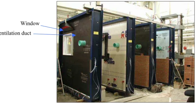
The wall specimens combined different types of claddings, sheathing membranes and boards, and insulation of typical use in North American construction. Cladding types included stucco, brick veneer, hardboard and vinyl siding, and exterior insulation and finish systems (EIFS). Certain cladding systems included a clear continuous air space. Sheathing boards included glass mat gypsum board, oriented strand board (OSB), fibreboard and XPS (extruded polystyrene) foam sheathings (Figure 1). Deficiencies included discontinuities of rain penetration control elements at junctions with windows, ventilation ducts and electrical outlets, such as a missing length of sealant or construction
tape.
Window Ventilation duct
Figure 1. Full-scale 2400-mm by 2400-mm test specimens shown at different stages of fabrication. Four of the 17 wall specimens included brick veneer.
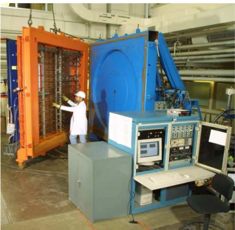
Researchers subjected each wall specimen to simulated wind-driven rain of various intensities in IRC’s unique Dynamic Wind and Wall Testing Facility (DWTF) and investigated how much water got deposited in the stud cavity under a variety of climate loads (Figure 2).
Figure 2. IRC researchers use the Dynamic Wind and Wall Testing Facility to expose wall specimens to wind-driven rain loads and investigate where water (and how much) gets deposited into the layers of the wall assembly. The facility
comprises a water spray system that simulates the action of rain; a blower to
simulate wind effects; and a piston that, through its cyclic action, varies air pressure to simulate wind gusts.
Conditions for rain penetration
For water to enter into the wall assembly, three conditions must be met: presence of water on the facade, a force to drive it inwards and an opening providing a path for water to flow. The forces acting on the façade to cause water penetration are: gravity, capillary action, air pressure difference, surface tension, and kinetic energy of the raindrops. Two key climatic factors to include in a laboratory testing program are wind speed and rainfall intensity. Higher wind speeds cause a greater air pressure differential across the wall and cladding elements, which will cause the water present at deficiencies in the cladding assembly (e.g., missing length of sealant) to infiltrate the layers of the wall. Deficiencies are often found at the interface between the wall and openings for windows, ventilation ducts and electrical outlets and thereby potentially offer a direct path for water entry.
Simulating wind-driven rain in a laboratory setting
Watertightness performance testing should be based on climatic design criteria such as those given by ASTM and the rainfall intensities and wind speeds expected in a given location. In IRC’s test facility (Figure 2) a continuous spray of water is applied on a wall specimen while subjecting it to a specified air pressure differential. This test is useful for determining loads at which failure may be observed, the nature and location of the failure, and insights into the vulnerability of different wall components to water entry.
For the MEWS project, the watertightness performance test used a series of different spray rates and air pressure differentials to simulate extreme wind-driven rain intensities. These included spray levels typically used in industry performance tests and a range of pressure differentials representing expected occurrences of elevated wind speeds across Canada and the United States. In a typical test, deficiencies, such as missing sealant at interfaces with windows, ventilation ducts and electrical outlets, were incorporated in a test specimen and water was sprayed on the wall. The water entering through the gaps was collected in troughs located in the stud cavity directly below the penetrating component.
Benefits of a drained air space behind the cladding
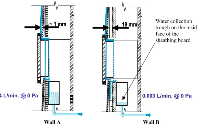
One aspect of the laboratory investigation examined the benefits of a drained clear cavity behind the cladding. Results showed that a clear drained air space behind the cladding considerably reduced the water load into the stud cavity of the wall. Figure 3 shows a sectional view at a ventilation duct penetration of a wall test specimen having two
different cladding configurations: one with a clear air space (use of vertical furring strips) and one without it. Water infiltration into the stud cavity was permitted by leaving out sections of sealant at the junction between the wall and the ventilation duct, providing a path for water to get in. A large portion of the infiltrating water was drained into the clear air space behind the cladding, where it could be evacuated outside through the use of proper flashing techniques. The water load into the stud cavity was about 10 times less for the specimen containing a drained cavity (Wall B) as compared to the one without it (Wall A).
In Canada the installation of a clear drained cavity behind cladding systems has been considered a best practice in the application of the rainscreen principle formulated over forty years ago. It provides a level of redundancy in the wall assembly for rain
penetration control because of its capability to provide three key mechanisms of control: drainage of incidental water entry, a capillary break to trapped water, and its potential for reducing pressure differentials across the cladding.
Interestingly, the IRC test results also indicated that even with the presence of this clear drained cavity behind the cladding, a small quantity of water could still find its way into the stud cavity. The path for water leakage was provided by the presence of
discontinuities at the junction between the ventilation duct and the water-resistive
space was present behind the cladding system, it was beneficial to ensure that the component of the assembly acting as second line of defence, be it a water-resistive membrane or a board stock material, be attached in a water-resistant manner to
penetrating elements such as ventilation ducts, electrical outlets, and windows to ensure the continuity of this second line.
Conclusion
Including an air space behind the cladding and ensuring the continuity of the water-resistive layer on the outside of the stud cavity are two design strategies that promote the long-term service life of the structural elements of wall assemblies.
19 mm ~ 1 mm 0.003 L/min. @ 0 Pa 0.04 L/min. @ 0 Pa 19 mm 19 mm ~ 1 mm ~ 1 mm 0.003 L/min. @ 0 Pa 0.04 L/min. @ 0 Pa Water collection trough on the inside face of the
sheathing board
Wall A Wall B
Figure 3. Cross-sectional view of two siding-clad wall sections at the ventilation duct penetration. Wall A did not have a clear continuous air space over the height of the wall, whereas Wall B included a clear 19-mm air space provided by vertical furring strips.
Further reading
• Exterior wall design using the rainscreen principle has been documented in several IRC Construction Technology Updates, such as nos. 9, 17, 23 and 34. These can be downloaded from the IRC website: http://irc.nrc-cnrc.gc.ca/catalogue/ctu.html
• MEWS project reports and related articles can be found on the IRC website at
This article is an extract of a paper and talk authored by Dr Michael Lacasse, presented at IRC’s Building Science Insight 2003 seminar series held across Canada from October 2003 to January 2004. Dr. Lacasse is a senior research officer in the Building Envelope and Structure program of the National Research Council’s Institute for Research in Construction.


