Publisher’s version / Version de l'éditeur:
Journal of Thermal Insulation and Building Envelopes, 16, Oct, pp. 183-192,
1992-10
READ THESE TERMS AND CONDITIONS CAREFULLY BEFORE USING THIS WEBSITE. https://nrc-publications.canada.ca/eng/copyright
Vous avez des questions? Nous pouvons vous aider. Pour communiquer directement avec un auteur, consultez la première page de la revue dans laquelle son article a été publié afin de trouver ses coordonnées. Si vous n’arrivez pas à les repérer, communiquez avec nous à [email protected].
Questions? Contact the NRC Publications Archive team at
[email protected]. If you wish to email the authors directly, please see the first page of the publication for their contact information.
NRC Publications Archive
Archives des publications du CNRC
This publication could be one of several versions: author’s original, accepted manuscript or the publisher’s version. / La version de cette publication peut être l’une des suivantes : la version prépublication de l’auteur, la version acceptée du manuscrit ou la version de l’éditeur.
For the publisher’s version, please access the DOI link below./ Pour consulter la version de l’éditeur, utilisez le lien DOI ci-dessous.
https://doi.org/10.1077/109719639201600209
Access and use of this website and the material on it are subject to the Terms and Conditions set forth at
Performance of pressure equalized rainscreen walls under cyclic
loading
Baskaran, B. A.; Brown, W. C.
https://publications-cnrc.canada.ca/fra/droits
L’accès à ce site Web et l’utilisation de son contenu sont assujettis aux conditions présentées dans le site LISEZ CES CONDITIONS ATTENTIVEMENT AVANT D’UTILISER CE SITE WEB.
NRC Publications Record / Notice d'Archives des publications de CNRC:
https://nrc-publications.canada.ca/eng/view/object/?id=e3206062-e985-4f7d-b774-e0a5bd595bae https://publications-cnrc.canada.ca/fra/voir/objet/?id=e3206062-e985-4f7d-b774-e0a5bd595baehttp://www.nrc-cnrc.gc.ca/irc
Pe rform a nc e of pre ssure e qua lize d ra insc re e n w a lls unde r c yc lic
loa ding
N R C C - 3 5 5 1 5
B a s k a r a n , B . A . ; B r o w n , W . C .
O c t o b e r 1 9 9 2
A version of this document is published in / Une version de ce document se trouve dans:
Journal of Thermal Insulation and Building Envelopes,
16(Oct), pp. 183-192,
October, 1992, DOI:
10.1177/109719639201600209The material in this document is covered by the provisions of the Copyright Act, by Canadian laws, policies, regulations and international agreements. Such provisions serve to identify the information source and, in specific instances, to prohibit reproduction of materials without written permission. For more information visit http://laws.justice.gc.ca/en/showtdm/cs/C-42
Les renseignements dans ce document sont protégés par la Loi sur le droit d'auteur, par les lois, les politiques et les règlements du Canada et des accords internationaux. Ces dispositions permettent d'identifier la source de l'information et, dans certains cas, d'interdire la copie de documents sans permission écrite. Pour obtenir de plus amples renseignements : http://lois.justice.gc.ca/fr/showtdm/cs/C-42
"
,
Performance of Pressure Equalized
Rainscreen Walls under Cyclic Loading*
BASA. BASKARAN AND WILLIAM C. BROWN Building Performance Section
Institute for Research in Construction National Research Council of Canada
Ottawa, Ontario
Canada KIA OR6 1. INTRODUCTION
W
IND-INDUCED PRESSURE difference is one of the forces that con-tributes to rain penetration ofwalls. It can be attenuated by using the pressure equalized rainscreen (PER) approach to wall design. In such a wall an air space that is located inside the exterior cladding is vented to the out-side so that the pressure on the inout-side of the cladding equalizes to the pressure on the outside. As pressure equalization is the key element of the process, it is important that the system be fast enough to respond to mostchanges in exterior pressure.
In 1963, Garden introduced the concept of the "open rainscreen" to build-ing designers. The significance of this work lies in the formulation of basic design guidelines. These have subsequently been modified on several occa-sions in order to address the complicated nature of the interaction between wind-driven rain and wall systems. Killip and Cheetham (1984) reviewed the process of rain penetration through walls. They also performed simplified experiments to measure the pressure drop in the cavity for various venting and leakage conditions.
Field measurements on PER walls were undertaken by researchers at the Institute for Research in Construction of the National Research Council セヲ
Canada (IRC/NRCC). From June 1983 to October 1984, the Place Air
セ i
I
I
•
1
1
セ
1
r
セ
,
I セ1
I
! f I I I.,
1.*Presented at CIB92. World Building Congress. Montreal, May 18-22. 1992.
J.THERMAL INSUL. AND BLDG. ENVS. Volume16-October 1992
1065-2744/92/020183-11 $06.00/0 ©1992 Technomic Publishing Co.. Inc.
184 BASA. BASKARAN AND WILLIAMC. BROWN
Canada building in Montreal was monitored for pressure equalization per-formance (Ganguli and Dalgliesh. 1988). Brown et a1. (1991) reviewed the performance of Place Air Canada's wall as well as reporting on the moni-tored performance of a PER wall on a low-rise building in Alberta.
Recently Baskaran (1991) conducted a systematic literature review to de-termine available design guidelines for PER walls. One conclusion drawn from the review was that current design guidelines are not at all compre-hensive. As a consequencelRC/NRCChas initiated a research project to de-velop, through computer modelling and experimental studies, design guide-lines for PER walls. The intended audience is architects, engineers, and building envelope designers. This article discusses the progress to date and the future directions of this ongoing research.
2. COMPUTATIONAL METHODOLOGY
For computer modeling of the performance of PER walls. a simplified wall segment is considered. Its schematic is shown in Figure 1.The mathe-matical model includes the three princip'l components of a physical model:
1. The exterior cladding orRainscreen
2. The air space or Cavity
3. The interior surface, which is an effectiveAir Barrier System
BuildingExterior
WInd Driven Rain
セセ
セセ
Ralnscreen 1) Totalventing area 2)VentingIOcatlon 3) Venting dimension 4)RaInscreendesignIOaltS
5)RaInfcteenI1iffro&ea
1)Ef'fecIIv8Ieakagearea
2)AJtbarrier de8lgnJoada
3) AIrbarrieretiffnus
4)NtbanIerrasten,,,,
Pressure Equlllzation Cavtty
1) Cavity depth 2)Compartment lid 3)DesignIoad8onMaSs
.'
"Performanceof Pressure Equalized Rainscreen Walls under Cyclic Loading 185
Each component has a number of design features that are also listed in Figure I. Successful pressure equalization performance of a PER wall de-mands design guidelines for all these features.
Let us label the area of the wall as Awand the area of venting as Av • De-noting the mean pressures on the exterior, cavity, and interior as P., Po and
P, and assuming only steady state incompressible flow conditions dominate the pressure equalization process, the flow rate through the venting on the
rainscreen can be calculated as:
(1)
Since Av is intentionally provided to promote pressure equalization, this
flow rate is termed as "venting through the rainscreen:' Unavoidably, there will be cracks and porosity in the cladding through which there will also be flow. It can be termed "leakage through the rainscreen" and calculated as:
(2) The air barrier system should by design be airtight. However, there may be flaws in the design or in its implementation; consequently, there will be flow, or leakage, through the air barrier system. This "leakage through the
air barrier" can be calculated as:
(3) As will be discussed in the following section, holes were drilled in the air barrier system during the experiment to provide controlled leakage condi-tions. This "deliberate leakage through the air barrier" can be calculated as:
Using the above equations in the continuity condition yields:
Qv
+
qセ=
QL+
QlFor a given wall system the above relationship takes the form: C.(P. - P.)"
+
C,[(P. - p.)m - (P. - p,)m]=
C,(Pc - P,)"(4)
(5)
186
where
BASA. BASKARAN AND WIlliAM C. BROWN
C,
=
CD,AvHセイ
C, = CD,AL ( ; ) " (7)
Equation (6) is implicit in nature and the cavity pressure is the unknown; it can be solved using an iteration procedure. Note that in Equation (7) the
same discharge coefficient is used for leakages through the rainscreen and air
barrier.
Another factor that needs to be discussed is the time lag of the cavity pressure response. Raleigh (1945) developed an equation for resonance fre-quency based on the theory of the Helmholtz resonator. For an enclosed volume, V.. the resonant frequency, RI , in Hz is given by:
(8) For the present study, the conductivity of the aperture area,
r,
is calculated as:イ]Rセ
(9)The cavity is assumed to be unsegmented and its volume can be calculated
as:
(10) The expression for the time lag,1,(= lIRI ),of the response can be obtained by using the Equations (9) and (10) in Equation (8) and simplifying as:
1 1 , = - - - = =
57.48
セZZ[N
,
.
Peiformance of Pressure Equalized Rainscreen Walls underCyclicLoading 187
Equation (11) indicates that the time lag,I" is a constant for given wall pa-rameters. In the computer model, the time of the cavity pressure was ob-tained by adding this constant value to the time of the external pressure.
3. EXPERIMENTAL PROCEDURE
Experiments using the Dynamic Loading Facility (DLF) of IRC/NRCC
have been conducted to evaluate the pressure equalization process. The
facil-itycan generate sinusoidal, square or triangular pressure waves on a wall test
specimen so that the dynamic (frequency) components of a typical wind loading can be simulated. A more complete description of the DLF can be found from Dalgliesh and Taylor (1990).
The tested wall specimen was 1.5 m wide by 2.1 m high and consisted of a reinforced 100 mm brick veneer Rainscreen, an insulation-filled (mineral wool) 100 mm thick Cavity, and a steel stud supported, 12 mm thick, foil-covered gypsum board Air Barrier System. Venting was achieved by open-ing/closing the head joints at the bottom ofthe brick veneer. Deliberate leak-age through the air barrier system was achieved with holes drilled in the gypsum board.
To evaluate pressure equalization performance, the wall system was excited
by sinusoidally varying pressure fluctuations on the exterior ofthe specimen while the pressure on the interior was kept constant. The external cyclic pressure can be expressed as:
P.(t)
=
p.+
A.sin (2./t) (12) The mean component, p .. was maintained at approximately 2 kPa and the amplitude, A.. at 1 kPa. The response was measured for a range of frequen-cies,J,
from 0.1 Hz to 2 Hz, a range that covers the major portion of the wind spectrum (Davenport, 1961). Pressure differences across the wallspeci-men and across the Air Barrier System were measured; pressure difference across theRainscreenwas calculated from these measurements.
4. RESULTS AND DISCUSSION
This section compares calculated cavity pressureto the measured data for several venting and leakage conditions. The parameters of the wall specimen and the external pressure conditions [Equation (12)] served as inputs for the computer model.
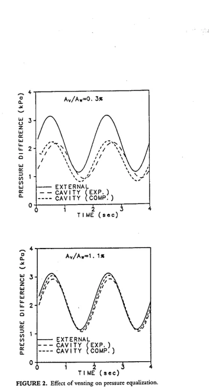
Figure 2 compares the experimental cavity response with the computed results. 1\vo venting areas, normalized against total wall area, are presented. As would be expected, pressure equalization performance improves as
vent-セ
..
c Av/Aw=O. 3,."-""
セ UJ 3 u z UJ'"
UJ/;
...
,,'\
"";'\,-...
2"
/ \' -' I \セ 0,
/1 \ /,,
// \ UJ /,
'"
,
/1,
:::J,
,
\ ....//"
,
VI '....
-VI '.-UJ EXT ERNAL
'"
CAVITY セ EXP. ) "- CAV I TY CaMP. ) a 4 1 2 TIME ( • e c) Av/A w=1. ,,. セ4 , . - - - ,
c"-""
セ セ 3 z UJ"'
!oJ...
... 2 o UJ'"
:::J VI VI UJ'"
"-EXTERNAL CAVITY (EXP.) CAV I TY (COMP.)o
t---,---r---r---l
4 TIME (.ee)FIGURE 2. Effect of venting on pressure equalization.
Performance of Pressure Equalized Rainscreen Walls under Cyclic Loading 189
ing area increases. Increasing venting area also leads to an improvement in the agreement between the computed and experimental cavity pressure. However, some difference is noted between the computed and measured
phase of the response.
In an efficient PER wall design, the pressure difference across the rain-screen (the difference between the external and cavity pressure) is nearly
equal to zero. In the present data analysis. the pressure difference across the
rainscreen was calculated for both approaches. Comparisons of the com-puted results with rhe experimental data (nor shown) agreed well for the amplitude and with the same discrepancy in the phase.
Figure 3 presents a comparison of cavity response for two leakage ratios. Increasing the leakage area has a negative effect on pressure equalization
per-formance. In general the experimental and computed cavity pressures show
good agreement.
In the past, pressure equalization performance has been analyzed based on the time history, as shown in Figures 2 and 3, or on load sharing factors, i.e., the ratio of the peak external load to the peak load on the rainscreen. These methods depend on either the duration or the magnitude of the external loading only, and it is rather difficult to compare performance between wall systems. The present study evaluates the performance of the PER wall by calculating an index called the Pressure Equalization Index (PEl). It is defmed as follows: N
I;
P:(t) NI;
P:(t) PEI(%)=
1 - -LGZZNセエ⦅NL⦅MZZBZZN」エ」M⦅ NI;
PM
1=1x
100 (13)PEl indicates the overall pressure equalization performance directly. For example, a value of 100% means that the cavity pressure is perfectly equalized with the external pressure. Similarly, a value of 10% indicates sig-nificant pressure difference between the cavity and the exterior. Thus PEl will be useful in rating the system performance under various design param-eters such as venting area, leakage area, and cavity volume.
Figure 4 shows the PEl values calculated from the computer modeling and from the experimental data.
In general, the PEl is above 50% for all venting/leakage conditions con-sidered. For all leakage areas considered, the PEl was found to increase with venting area. Figure 4 also reveals that the computed values are higher than the experimental ones for all conditions considered.
セ 4 0 A./Aw=O. PWセ a.
'"
セ UJ J ? u,
z セ UJ セ 0: UJr
...
2r
0r
UJ セ 0: :J VI EXTERNAL VI UJ - - CAVITY (EXP.) 0: ----CAViTY COMP.) a. 0 0 J 4 T I ME (s e c) A./Aw=O. 1'", セTMイMMMMMMMMMMMMMMMLo a....
tj • z UJ 0: UJ...
....
o UJ 0: :J VI VI UJ 0: 0.. EXTERNAL - - CAVITY (EXP.) ---- CAV I TY (COMP.) O+----,----r---y----; 4FIGURE 3. Effectof leakagearea on pressure equalization.
)
.
Performance ofPressure Equalized Rainscreen Walls under Cyclic Loading 191
EXPERIMENT
COMPUTED
Av/Aw=O. 3ll>
Av/A w=l. Ill>
Av/A w=0.5ll>
1 0 0 - - - = , - - - ,---セ
\"
\ I \ \ \ \ \ \ \ \ \ \ セ•
セ >< 90..,
Cl Z z 80 Cl...
セS
60...
;'l 70..,
'"
::> セ50
..,
'"
..
0.20 O. 15 O. 10O.
05
40't---,----,---r----; 0.00FIGURE 4. Computed。セ、 experimental PEl for different venting/leakage conditions.
5. SUMMARY
IRC/NRCChas begun a research project to develop design guidelines for PER walls. This project involves development of both a computer model to simulate PER wall performance and laboratory and field experiments to measure actual wall performance. As a first step in the project, a computer model based on incompressible flow equations has been developed; in addi-tion, parametric studies of a brick veneer PER wall have been conducted in the laboratory. Comparison of the computed results with the experimental
data is encouraging.
An index, called the Pressure Equalization Index. has been proposed as a method of evaluating and comparing the performance of PER walls. It is
in-tended to minimize some of the restrictions that are inherent in previous
evaluation methods. All of the configurations examined to date have had a PEl of at least 50%. Analysis of the results from these configurations in-dicates that a venting area of at least 1% of the wall area is necessary to equalize the cavity pressure with the external wind-induced pressure
fluc-tuations.
Additional research is required to confirm these observations for different driving forces and to determine the importance of other design features on
192 BASA. BASKARAN AND WILUAMC. BROWN
PER wall performance. Currently efforts are directed to extending the com-puter model to account for random external loading and unsteady flow con-ditions within the cavity. Experimental studies of other PER wall configura-tions are planned for the DLF; field measurements of PER wall performance will be conducted as the opportunity arises, and the use of a boundary layer wind tunnel for PER wall studies will be examined.
NOMENCLATURE A.
=
mean amplitude of the cyclic loading AL=
effective area of leakageAv
=
effective area of ventingAw
=
area of the wallCs
=
wall constants CDS=
dischargecoeffIcients d.=
cavity depthf
= frequency N=
number of samples n, In=
flow exponents p.=
cavity pressure p..=
external pressure Pi=
internal pressure Qs=
flow rates Rf=
resonant frequency t=
time t,=
time lag Vc=
cavity volume v.=
velocity of sound Q=
density of airr
=
conductivity of the aperture Abbreviations:DLF
=
Dynantic Loading Facility PER=
Pressure Equalized Rainscreen PEl=
Pressure Equalization IndexACKNOWLEDGMENT
The authors acknowledge the valuable contribution of Mr. G. F. Poirier who set up and conducted the experiments for the data presented in the arti-cle.
セ "
Perftrmance of Pressure Equalized Rainscreen Walls under Cyclic Loading 193
REFERENCES
1. Baskaran, A.1992. "Review of Design Guidelines for Pressure Equalized Rainscreen Walls;' Internal Report No. 629. Institute for Research in Construc-tion; National Research Council Canada, Ottawa, Canada.
2. Brown, W. C, M. Z. Rousseau and W. A. Dalgliesh. 1991. "Field Testing of Pressure Equalized Rainscrecn Walls:' ASTM STP 1034, Exterior Wall
Sympo-sium, Precast Concrete, Masonry and Stuao, Chicago) IL, pp. 59-69.
3. Dalglicsh,W.A.and D. A. Taylor. 1990. "The Strength of Window Glass:'
Cana-dian]ournal of Civil Engineering, 17:752-762.
4. Davenport, A. G. 1961. "The Spectrumof Horizontal Gustiness near the Ground in High Winds:' Quarterly]ournal of Royal Meteorological Society, 87:194.
5. Ganguli, U. and W. A. Daigliesh. 1988. "Wind Pressures on Open Rain Screen Walls: Place Air Canada:']ournal of Structural Engineering, 114(3):642-656.
6. Garden, G. K. 1963. "Rain Penetration and Its Control;' Canadian Building Digest
No. 40, Division of Building Research, National Research Council Canada, Ottawa, Canada.
7. KilIip, 1. R. and D. W. Cheetham. 1984. "The Prevention of Rain Penetration
through External Walls and JointsbyMeans of Pressure Equalization,"Journal of
Building and Environment, 19(2):88-91.
8. Rayleigh,L. 1945. The Theory
of
Sound, 2nd Ed. New York, NY: DoverPublica-tions.