HAL Id: hal-01348939
https://hal.inria.fr/hal-01348939v2
Submitted on 24 Oct 2016
HAL is a multi-disciplinary open access
archive for the deposit and dissemination of
sci-entific research documents, whether they are
pub-lished or not. The documents may come from
teaching and research institutions in France or
abroad, or from public or private research centers.
L’archive ouverte pluridisciplinaire HAL, est
destinée au dépôt et à la diffusion de documents
scientifiques de niveau recherche, publiés ou non,
émanant des établissements d’enseignement et de
recherche français ou étrangers, des laboratoires
publics ou privés.
Distributed under a Creative Commons Attribution - NonCommercial - NoDerivatives| 4.0
International License
3D Imaging from Video and Planar Radiography
Julien Pansiot, Edmond Boyer
To cite this version:
Julien Pansiot, Edmond Boyer. 3D Imaging from Video and Planar Radiography. MICCAI 2016
-19th International Conference on Medical Image Computing and Computer Assisted Intervention, Oct
2016, Athens, Greece. pp.450-457, �10.1007/978-3-319-46726-9_52�. �hal-01348939v2�
Julien Pansiot and Edmond Boyer
LJK, Inria Grenoble, France {julien.pansiot,edmond.boyer}@inria.fr
Abstract. In this paper we consider dense volumetric modeling of mov-ing samples such as body parts. Most dense modelmov-ing methods consider samples observed with a moving X-ray device and cannot easily handle moving samples. We propose a novel method that uses a surface mo-tion capture system associated to a single low-cost/low-dose planar X-ray imaging device for dense in-depth attenuation information. Our key contribution is to rely on Bayesian inference to solve for a dense atten-uation volume given planar radioscopic images of a moving sample. The approach enables multiple sources of noise to be considered and takes advantage of limited prior information to solve an otherwise ill-posed problem. Results show that the proposed strategy is able to reconstruct dense volumetric attenuation models from a very limited number of ra-diographic views over time on simulated and in-vivo data.
1
Introduction
The ability to capture intrinsic body structure in motion is of interest in a number of fields related to medical imaging such as computer-assisted surgery, biomechanics, and sports science. Many applications consider video or depth cameras and infer skeletal motion from surface observations using prior models. However, this strategy does not provide real measures on the internal structure and the estimated skeleton does not match the actual bone structure due to multiple factors such as inaccurate skeletal model and complex elastic tissue motion. With the aim to provide better measures to observe intrinsic structures in motion, and validation purposes, we investigate in this paper a new strategy that recovers dense 3D volumetric models of moving samples.
To this purpose, we combine a video-based surface motion capture system that provides motion cues, with a single static planar X-ray imaging device that captures the inner structure. We present the first step towards three-dimensional volumetric motion capture by investigating first rigidly moving samples, assum-ing limited prior knowledge on the captured samples. A key concept of our approach compared to traditional tomography is that it does not consider mo-tion as low-amplitude noise to be corrected, but at the contrary as a source of information, ensuring the capture of X-ray images from multiple viewpoints.
As a result, the proposed configuration can consider moving samples as well as several sensors (eg. two X-ray devices). Yet less accurate than a CT-scanner, it yields a less expensive low-dose solution, taking benefit of equipment widely available in clinical environments.
Author version HAL-v2. The final publication is available at Springer viahttp://dx.doi.org/10. 1007/978-3-319-46726-9_52.
2 3D sample in motion Projection + integration Geometric noise Image noise Single static X-ray C-arm Multiple
video cameras Flow field Noise kernel
Fig. 1. X-ray image formation model for a moving sample observed by a single static planar X-ray device. Video cameras are used to recover the sample motion.
Our volumetric reconstruction method builds on super-resolution techniques [6]
to optimally exploit X-ray samples and infer 3D attenuation. It relies on an X-ray
image formation model (see Fig.1) accounting for 2D sensor noise as well as 3D
geometric errors. This model is associated with a volumetric L1smoothness prior
to constrain the reconstruction, allowing for a limited number of input views. All these elements are integrated within a Bayesian framework for backward inference.
To summarize, the key contribution introduced in this paper is a Bayesian approach to 3D imaging of a moving sample which accounts for both sensor and calibration inaccuracies using a generative model.
2
Related Work
Currently, the two well-established classes of methods to recover attenuation models are planar radiography and Computed Tomography (CT). The former can capture motion at competitive frame rates with a low dose, but is limited to integrated two-dimensional information. The latter, in the form of Multi-Detector CT (MDCT) and Electron Beam CT (EBCT), can capture accurate dense 3D volumetric attenuation models at up to 30 fps, yet exposing patients to higher ionising radiations, present much higher costs, and limited versatility. For these reasons, few-views cone-beam computed tomography (CBCT)
tech-niques [4] have gained interest. Several methods have been devised to reconstruct
relatively accurate 3D attenuation models from a limited number of cone-beam
images [1,10]. Nevertheless these methods are limited to static samples.
The combination of motion capture and emission tomography has also been
investigated but either requires markers [7], or is designed for low-amplitude
mo-tion correcmo-tion [5]. Similarly, motion correction in tomography has been largely
covered in traditional CT/PET [3] as well as CBCT [11]. Again, our strategy
dif-fers since we consider motion as a mean to vary viewpoints which helps capturing moving samples.
A method to reconstruct 3D attenuation from a limited number of arbitrary
X-ray views was proposed in [9], but assumes reasonably good calibration. The
general approach by [8] reconstructs volumetric attenuation from a limited
num-ber of X-ray views of a moving object which motion is estimated using videos. While building on a similar concept, we take however a different and more
for-mal generative strategy inspired by image super resolution[6]. In this domain,
Bayesian inference methods have demonstrated their ability to optimally exploit noisy observations with uncertainty modelling and we extend them to our X-ray imaging configuration.
3
Generative image model
As mentioned, our generative model builds on existing image formation model
[6] to explain the X-ray images given the 3D model. Our method takes as input
a set of X-ray images of a rigidly moving sample. The images are first registered in a common framework using the motion estimated by a multi-view motion capture system. A dense attenuation model of the moving sample, represented as a voxel grid, is then reconstructed using the entire X-ray image sequence.
We detail below the main components of this model. In order to account for the multiple sources of noise present in the acquisition process, we introduce
a generative image formation model, as illustrated in Figure 1. This model is
associated with a sparse prior, ie. a TV-norm.
3.1 Image formation
We discretise the continuous absorbance problem in 3D as a weighted sum over
the voxels vjalong the given ray ω, djbeing the distance covered within the voxel
vj and µj the attenuation assumed uniform within vj, defining the absorbance
I(ω) in function of the emitted and transmitted intensities L0 and L(ω):
I(ω) = logL(ω)
L0
= −X
j∈ω
djµj. (1)
In real scenarii however, several sources of noise affect the image formation, and therefore a more comprehensive image formation model must be devised as
illustrated in Fig.1. We consider a sequence of images I = {Ii} acquired from a
volume discretised as a voxel grid with attenuations V = {µj}. For each image
Ii we have:
1. A known projection and integration matrix Pi composed of the coefficients
dj obtained from motion capture. In the ideal case, we would have PiV = Ii.
We denote the projection matrix concatenation for all images P = {Pi}.
2. A 2D image noise variance θi accounting for the light source, the amplifier,
and the imaging sensor.
3. Geometric noise, ie. the errors in the projection Pi. This includes the
inac-curacy in the motion and projection estimation as well as the deviation from
4
3.2 Bayesian model
Our aim is to recover the 3D attenuation V given the absorbance image sequence I, ie. to invert the model described previously. For this purpose we rely on a MAP estimation to find the optimal solution in terms of attenuation and noise:
{V∗, {Fi}∗, {θi}∗} = argmax V,{Fi},{θi}
p(V, {Fi}, {θi})|{Ii}), (2)
where, assuming statistical conditional independence between images given the attenuation model: p(V, {Fi}, {θi})|{Ii}) ∝ p(V ) Y i p(Fi) Y i p(θi) Y i p(Ii|V, Fi, θi). (3)
3.3 Priors and image likelihood
Geometric noise appears as a result of calibration inaccuracies and non exactly
rigid object motions. We modeled it by a warping function Fi, estimated using
the optical flow wi[2] between the observed image Iiand the generated one PiV .
As the inverse problem (3) is ill-posed and noise-ridden, we introduce noise
and model priors. Given the nature of the data typically observed, the sparsity of the derivative responses is used as a prior for the 3D attenuation volume as in [6]:
p(V ) = ηdim(V )e−ηk∇V k, (4)
where η is the gradient weight. The minimisation of the L1norm of the gradient,
or Total Variation T V L1, favours continuous volumes separated by potentially
high, albeit localised gradients.
The likelihood distribution is modeled as an exponential distribution: p(Ii|V, Fi, θi) = θ
dim(Ii)
i e−θikIi− FiPiV k. (5)
where the 2D image noise variance θi follows a Gamma distribution [6].
4
Model estimation
In order to solve for the parameters in the MAP estimation (2), we use a
coor-dinate descent scheme [6], that iteratively cycles through the independent
esti-mation of each parameter: the original volume V using expressions (4) and (5),
image noise variance θi, and the motion noise warp Fias detailed in section3.3.
Attenuation Volume Given the current estimates for the warping function Fiand
noise θi, we estimate the volume based on the image set {Ii} and the gradient
prior η with Iteratively Reweighted Least Squares (IRLS) to minimise:
V∗= argmin
V
X
i
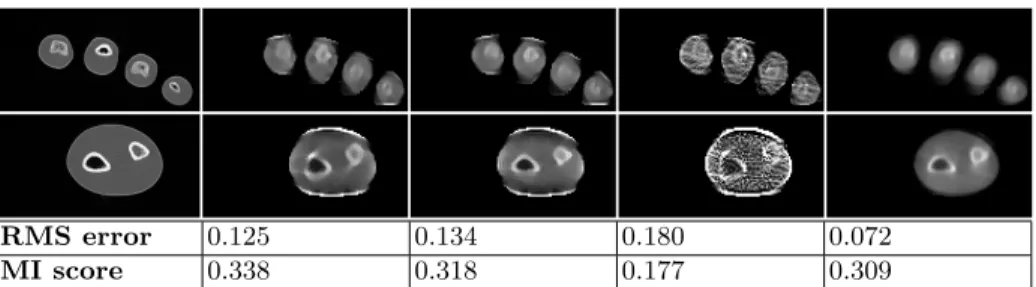
RMS error 0.125 0.134 0.180 0.072
MI score 0.338 0.318 0.177 0.309
Fig. 2. Results on simulated data (2 selected slices, RMS, and Mutual Information (MI) score). Left-to-right: ground-truth CT scan, proposed method, without optical flow, without T V L1 prior, ART [8]. Without T V L1 prior, the algorithm does not
converge. The contrast is better with the proposed approach (better MI as compared to ART) even though artefacts appear on the edges as a result of aliasing during the data simulation process (higher RMS as compared to ART). ART performs relatively well in part due to the fact that simulated data are close to the noiseless theoretical model.
Image/sensor noise Given the current volume V of N voxels and flow field Fi
we estimate the image noise variance θi based on the residual error following a
gamma distribution: θi∗= α + N − 1 β + x with x = N X q=1 |(Ii− FiPiV )(q)|, (7)
Geometric correction The residual motion is estimated using the optical flow
wi [2] between the observed image Ii and the projected volume PiV . Given the
current volume V and the noise variance θi, we estimate the flow wi associated
to the warp matrix Fi. We then reformulate the data term in (6) as:
X
i
θikPiV − Fi−1Iik. (8)
5
Experiments
Three sets of experiment were carried out to validate the proposed framework. First the CT scan of a phantom model was used to simulate image observations. Secondly, the phantom model was placed into our hardware platform. And third, an in-vivo hand was captured and reconstructed using the proposed framework.
5.1 Simulated radiographic and video data from CT
A forearm phantom, consisting of a real human forearm skeleton cast in resin was first scanned with a regular CT device. A complete capture pipeline was then simulated from the phantom scan which was rendered by 10 virtual video
6
Fig. 3. Results on simulated data (selected slice) based on varying numbers of input frames. Left-to-right: 8, 16, and 32 frames. Skeletal structures are visible with 16 frames when detailed features require 32 frames.
Fig. 4. Results on simulated data (se-lected slice) based on varying input an-gular range. Left: 32 frames roughly distributed over 180 degrees; right: over 90 degrees.
Fig. 5. Results on the simulated data (raycasting ren-dering) based on varying input angular range. Left: 32 frames roughly distributed over 180 degrees; right: over 90 degrees. The rendered viewpoint falls within the range of the original 90 degrees motion, but not on an original viewpoint, leading to sharper rendering due to locally denser sampling.
cameras and one virtual planar X-ray image1. The phantom scan model was
then moved artificially, following roughly a 180 degrees rotation. The phantom motion was estimated using video and Iterative Closest Point for comparison
with [8]. The proposed approach was then applied to the simulated data.
The performance of individual components of the algorithm were analysed
independently, as illustrated in Fig. 2. We note that on simulated data, our
approach exhibits slightly better contrast than ART (higher Mutual Information (MI) score). We also evaluate the sensitivity of our method with respect to the
number of input frames, as illustrated in Fig.3. These experiments show that for
the given dataset, main skeletal structures can be recovered with as little as 16 frames. However, finer features such as bone cavities require at least 32 frames. Furthermore we reduce the motion range from 180 to 90 degrees, which clearly
impacts the volumetric estimation quality, as illustrated in Fig. 4. Raycasting
rendering of the volume yields sharper results for poses within the original motion
range, due to increased sampling density, as illustrated in Fig.5.
5.2 In-situ forearm phantom
The proposed platform is composed of ten colour video cameras and a single X-ray C-arm. The forearm phantom presented here above was placed into the capture platform and moved manually to follow roughly a 180 degree rotation. The volumetric results were compared to the original CT model. Unlike the simulated experiment, the CT model and the model reconstructed with the C-arm images are in different poses since they correspond to 2 different acquisitions 1
Input data and more results for simulated and in-vivo experiments are available here:
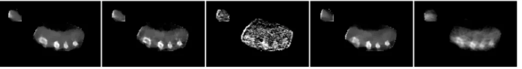
MI score 0.146 0.137 N/A (failed) 0.094
Fig. 6. Results on the forearm phantom (2 selected slices and Mutual Information (MI) score). Left-to-right: ground-truth CT scan, proposed method, without optical flow, without T V L1 prior, ART [8]. Without optical flow, artefacts are visible, for
example in the bone cavities. The ART method produces much noisier results.
Fig. 7. Results on the in-vivo hand with different priors (selected slice). Left-to-right: T V L1 weight η = 2; η = 1; η = 0 (no T V L1 prior); no optical flow prior; ART
[8]. The first three reconstructions demonstrate the favourable impact of the T V L1
prior. Comparing the first and fourth reconstruction (no optical flow), we observe less artefacts with flow and the bones are better resolved, in particular the index. ART exhibits a lot of under-sampling artefacts that cannot be recovered without priors.
of the phantom, as illustrated in Fig. 6. Furthermore, the energy spectrum of
the CT scanner and that of the low-dose X-ray C-arm are different. Hence, the two models are first registered using multi-resolution Mutual Information (MI). The MI score is provided for quantitative comparison, being invariant to attenuation spectrum. Unlike the simulated case, this experiment shows that the proposed method performs significantly better than ART. In particular, the use of optical flow for motion noise compensation allows to retain a fair level
of detail, whilst the T V L1 norm prior constrains the ill-posed problem without
excessive blurring.
5.3 In-vivo human hand
Finally, an actual in-vivo human hand was moved in the field, again following
roughly a rotation movement over 20 frames. The results presented in Fig. 7
demonstrate the benefit of our approach which improves the results in some spe-cific areas which we attribute to local (ie. non-rigid) motion. This demonstrates the interest of the generative model with the optical flow correction and the TV L1 regularization over more traditional approaches for few-view CBCT.
8
6
Conclusions and Future Work
In this paper we have presented a novel generative model to estimate a dense volumetric attenuation model of a rigidly moving object using motion tracking and a single planar X-ray device. Our framework contributes with an approach that takes benefit of object motion to accumulate evidence on the object inner structure. To this aim, we have introduced a Bayesian approach that optimally exploits X-ray information while enabling for acquisition noise. Our experiments
show that the T V L1prior on the attenuation volume fundamentally contributed
to convergence without excessive blurring, and that geometric noise can be ef-fectively corrected using optical flow. This work considers rigid motion and we are currently investigating non-rigid motion.
Acknowledgements
This research was partly funded by the KINOVIS project (ANR-11-EQPX-0024).
References
1. Bang, T.Q., Jeon, I.: CT reconstruction from a limited number of X-ray projections. World Academy of Science, Engineering and Technology 5(10), 488–490 (2011) 2. Bruhn, A., Weickert, J., Schn¨orr, C.: Lucas/Kanade meets Horn/Schunck:
Com-bining local and global optic flow methods. IJCV 61(3), 211–231 (2005)
3. Dawood, M., Lang, N., Jiang, X., Schafers, K.: Lung motion correction on respi-ratory gated 3-D PET/CT images. TMI 25(4), 476–485 (April 2006)
4. Feldkamp, L.A., Davis, L.C., Kress, J.W.: Practical cone-beam algorithm. Journal of the Optical Society of America (JOSA) A 1(6), 612–619 (1984)
5. Hutton, B.F., Kyme, A.Z., Lau, Y.H., Skerrett, D.W., Fulton, R.R.: A hybrid 3-D reconstruction/registration algorithm for correction of head motion in emission tomography. IEEE Transactions on Nuclear Science 49(1), 188–194 (2002) 6. Liu, C., Sun, D.: On Bayesian adaptive video super resolution. TPAMI 36(2), 346–
360 (Feb 2014)
7. McNamara, J.E., Pretorius, P.H., Johnson, K., Mukherjee, J.M., Dey, J., Gennert, M.A., King, M.A.: A flexible multicamera visual-tracking system for detecting and correcting motion-induced artifacts in cardiac SPECT slices. Medical physics 36(5), 1913–1923 (2009)
8. Pansiot, J., Reveret, L., Boyer, E.: Combined visible and X-ray 3D imaging. In: MIUA. pp. 13–18. London (Jul 2014)
9. Sidky, E.Y., Kao, C.M., Pan, X.: Accurate image reconstruction from few-views and limited-angle data in divergent-beam CT. Journal of X-ray Science and Technology 14(2), 119–139 (2006)
10. Yang, G., Hipwell, J.H., Hawkes, D.J., Arridge, S.R.: A nonlinear least squares method for solving the joint reconstruction and registration problem in digital breast tomosynthesis. In: MIUA. pp. 87–92 (2012)
11. Zhang, Q., Hu, Y.C., Liu, F., Goodman, K., Rosenzweig, K.E., Goodman, K., Mageras, G.S.: Correction of motion artifacts in cone-beam CT using a patient-specific respiratory motion model. Medical Physics 37(6), 2901–2909 (2010)